
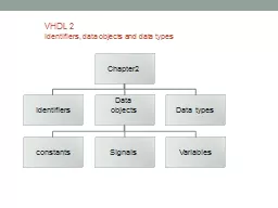
Identifiers data objects and data types VHDL 2 Identifiers data objects and data types ver6a 1 Identifiers It is about how to create names Used to represent an object constant signal or variable ID: 577729
Download Presentation The PPT/PDF document "VHDL 2" is the property of its rightful owner. Permission is granted to download and print the materials on this web site for personal, non-commercial use only, and to display it on your personal computer provided you do not modify the materials and that you retain all copyright notices contained in the materials. By downloading content from our website, you accept the terms of this agreement.


Slide1
VHDL 2Identifiers, data objects and data types
VHDL 2. Identifiers, data objects and data types ver.6a
1Slide2
Identifiers It is about how to create names
Used to represent an object (constant, signal or variable)
VHDL 2. Identifiers, data objects and data types ver.6a2Slide3
Rules for IdentifiersNames for users to identify data objects: signals, variables etc. First character must be a letter
last character cannot be an underscoreNot case sensitiveTwo connected underscores are not allowedExamples of identifiers: a, b, c, axy, clk ...
VHDL 2. Identifiers, data objects and data types ver.6a
3Slide4
Example: a,b,equals are Identifiers of signals
1 entity eqcomp4 is2 port (a, b: in std_logic_vector(3 downto 0);3 equals: out std_logic);4 end eqcomp4;56 architecture dataflow1 of
eqcomp4 is7 begin8 equals <= '1' when (a = b) else '0’;9-- “comment” equals is active high10 end dataflow1;
VHDL 2. Identifiers, data objects and data types ver.6a
4Slide5
Data objects
VHDL 2. Identifiers, data objects and data types ver.6a
5Slide6
Data objectsConstant
Signalsvariables
VHDL 2. Identifiers, data objects and data types ver.6a
6Slide7
Data objects: 3 different objects1 Constants: hold values that cannot be changed within a design.
e.g. constant width: integer :=82 Signals: to represent wire connectionse.g. signal count: bit_vector (3 downto 0)-- count means 4 wires; they are count(3),count(2), count(1), count(0).3 Variables: internal representation used by programmers; do not exist physically.
VHDL 2. Identifiers, data objects and data types ver.6a
7Slide8
Recall: if a signal is used as input/output declared in port
It has 4 modes
VHDL 2. Identifiers, data objects and data types ver.6a
8
e.g.
entity
eqcomp4
is
port (
a, b:
in std_logic_vector(
3
downto
0
);
equals:
out std_logic);
end
eqcomp4
;Slide9
Syntax to create data objectsIn entity declarations
VHDL 2. Identifiers, data objects and data types ver.6a
9Slide10
Constants with initialized valuesconstant CONST_NAME: <type_spec> := <value>;
-- Examples:constant CONST_NAME: BOOLEAN := TRUE;constant CONST_NAME: INTEGER := 31;constant CONST_NAME: BIT_VECTOR (3 downto 0) := "0000";constant CONST_NAME: STD_LOGIC := 'Z';constant CONST_NAME: STD_LOGIC_VECTOR (3 downto 0) := "0-0-"; -- ‘-’ is don’t care
VHDL 2. Identifiers, data objects and data types ver.6a
10Slide11
Signals with initialized valuessignal sig_NAME: type_name [: init. Value];
-- examplessignal s1_bool : BOOLEAN; -- no initialized valuesignal xsl_int1: INTEGER :=175;signal su2_bit: BIT :=‘1’;
VHDL 2. Identifiers, data objects and data types ver.6a
11Slide12
Variables with initialized valuesvariable V_NAME: type_name [: init. Value];
-- examplesvariable v1_bool : BOOLEAN:= TRUE;variable val_int1: INTEGER:=135;variable vv2_bit: BIT; -- no initialized value
VHDL 2. Identifiers, data objects and data types ver.6a
12Slide13
Signal and variable assignments SIG_NAME
<= <expression>; VAR_NAME :=<expression>;
VHDL 2. Identifiers, data objects and data types ver.6a
13Slide14
VHDL 2. Identifiers, data objects and data types ver.6a
14
Exercise 2.1: On signals
1-- 4-bit parallel load register with asynchronous reset
2-- CLK, ASYNC ,LOAD, : in STD_LOGIC;
3-- DIN: in STD_LOGIC_VECTOR(3
downto
0);
4-- DOUT: out STD_LOGIC_VECTOR(3
downto
0);
5 process (CLK, ASYNC)
6 begin
7 if ASYNC='1' then
8 DOUT <= "0000";
9
elsif
CLK='1' and
CLK'event
then
10 if LOAD='1' then
11 DOUT <= DIN;
12 end if;
13 end if;
14 end process
Fill in the blanks.
I
dentifiers
are:
__________
__________
__________
__________
__________
Input
signals
are:
__________
__________
__________
Signal arrays
are:
__________
__________
Signal type of DIN:
__________
Mode of DOUT
__________
Student ID: __________________
Name: ______________________
Date:_______________
(Submit this at the end of the lecture.)Slide15
Data typesDifferent types of wiresEach type has a certain range of logic levels
VHDL 2. Identifiers, data objects and data types ver.6a
15Slide16
Data types
VHDL 2. Identifiers, data objects and data types ver.6a
16Slide17
Data typesUser can design the type for a data object.E.g. a signal can have the type ‘bit’
E.g. a variable can have the type ‘std_logic’Only same type can interact.
VHDL 2. Identifiers, data objects and data types ver.6a
17Slide18
Types must match1 entity test
is port (2 in1: in bit;3 out1: out std_logic );4 end test;5 architecture test_arch of test is6 begin7 out1<=in1;8 end test_arch;
VHDL 2. Identifiers, data objects and data types ver.6a
18
Different types :
bit and std_logic
Not allowedSlide19
VHDL 2. Identifiers, data objects and data types ver.6a
19
Exercise 2.2:(a) Declare a signal “signx” with type bit in line 2
(b) Can you assign an IO mode to this signal (Yes or No) , and why? Answer:______________________________
1
Architecture
test2_arch
of
test2
2 ?_________________
3 begin
4 ...
5 …
6 end
test_archSlide20
VHDL 2. Identifiers, data objects and data types ver.6a
20
Exercise 2.3: (a) Where do you specify the types for signals?
(b)
Draw the schematic of this circuit.
1
entity
nandgate
is
2 port (in1, in2: in
STD_LOGIC;
3 out1: out
STD_LOGIC
);
4 end
nandgate
;
5 architecture
nandgate_arch
of
nandgate
is
6 signal
connect1
:
STD_LOGIC;
7 begin
8
connect1
<=
in1
and
in2
;
9
out1
<= not
connect1
;
10 end
nandgate_arch
;
Answer for (a) : Specify types of signals in
(i)____________________
(ii)____________________
Answer for (b)Slide21
Revision (so far we learned)(w3 begins)
Data objectConstants, signal, Variables Signal in port (external pins)InOutInoutBufferData typeMany types: integer, float, bit, std_logic, etc.
VHDL 2. Identifiers, data objects and data types ver.6a
21Slide22
VHDL 2. Identifiers, data objects and data types ver.6a
22
Exercise: 2.4:
1
entity
nandgate
is
2 port (in1, in2: in
STD_LOGIC;
3 out1: out
STD_LOGIC
);
4 end
nandgate
;
5 architecture nandgate_arch of nandgate
is
6 signal
connect1
:
STD_LOGIC;
7 begin
8
connect1
<=
in1
and
in2
;
9
out1
<= not
connect1
;
10 end
nandgate_arch
;
(a) Underline the IO signal
(b) Underline the Internal SignalSlide23
Different data types
VHDL 2. Identifiers, data objects and data types ver.6a
23Slide24
VHDL 2. Identifiers, data objects and data types ver.6a
24
Different data typesSlide25
Examples of some common typesType BOOLEAN is (FALSE, TRUE)
type bit is (‘0’ ,’1’);type character is (-- ascii string)type INTEGER is range of integer numberstype REAL is range of real numbersType Standard logic( with initialized values):signal code_bit : std_logic := ‘1’; --for one bit , init to be ‘1’, or ‘0’signal codex : std_logic_vector (1 downto 0) :=“01”; -- 2-bitsignal codey : std_logic_vector (7 downto 0) :=x“7e”; --8-bit hex 0x7eNote: Double quote “ ” for more than one bit Single quote ‘ ’ for one bit
VHDL 2. Identifiers, data objects and data types ver.6a
25Slide26
Boolean, Bit Types Boolean (true/false), character, integer, real, string, these types have their usual meanings. In addition, VHDL has the types: bit, bit_vector,
The type “bit” can have a value of '0' or '1'. A bit_vector is an array of bits.See VHDL Quick Reference http://www.doulos.com/knowhow/vhdl_designers_guide/
VHDL 2. Identifiers, data objects and data types ver.6a
26Slide27
Integer type (depends on your tool; it uses large amount of logic circuits for the implementation of integer/float operators) E.g.
Range from -(2^31) to (2^31)-1
VHDL 2. Identifiers, data objects and data types ver.6a
27Slide28
Floating type-3.4E+38 to +3.4E+38For encoding floating numbers, but usually not supported by synthesis tools of programmable logic because of its huge demand of resources.
VHDL 2. Identifiers, data objects and data types ver.6a
28Slide29
Enumeration types:How to input an abstract concept into a circuit ?E.g.1 color: red, blue, yellow, orange etc, we need 2 bits
E.g.2Language type: Chinese, English, Spanish, Japanese, Arabic. How many bits needed?Answer: 5 different combinations: 3 bits中文字, Chinese characters, caracteres chinos,漢字,الأحرف الصينية ,
VHDL 2. Identifiers, data objects and data types ver.6a
29
exerciseSlide30
Enumeration types:An enumeration type
is defined by listing (enumerating) all possible valuesExamples:type COLOR is (BLUE, GREEN, YELLOW, RED);type MY_LOGIC is (’0’, ’1’, ’U’, ’Z’);-- then MY_LOGIC can be one of the 4 values
VHDL 2. Identifiers, data objects and data types ver.6a
30Slide31
VHDL 2. Identifiers, data objects and data types ver.6a
31
Exercises 2.5Example of the enumeration type of the menu of a restaurant:
type food is (hotdog, tea, sandwich, cake, chick_wing);
(a) Declare the enumeration type of the traffic light.
Answer: _______________________________________
(b) Declare the enumeration type of the outcomes of rolling a dice.
Answer: _______________________________________
(c) Declare the enumeration type of the 7 notes of music.
Answer: _______________________________________Slide32
Define Array or a bus
VHDL 2. Identifiers, data objects and data types ver.6a
32Slide33
Std_logic_vector (array of bits) for bus implementationTo turn bits into a bus
‘bit’ or ‘std_logic’ is ‘0’, ‘1’ etc.Std_logic_vector is “000111”etc.1 entity eqcomp3 is2 port (a, b: in std_logic_vector(2 downto 0);3 equals: out std_logic);4 end eqcomp3;So a, b are 3-bit vectors:a(2), a(1), a(0), b(2), b(1), b(0),
VHDL 2. Identifiers, data objects and data types ver.6a
33
Bit_vector
bit
bitSlide34
VHDL 2. Identifiers, data objects and data types ver.6a
34
Exercise 2.6Difference between “to” and “downto”
(a) Given: signal
a
: std_logic_vector( 2 downto 0);
Create a 3-bit bus
c
using “to”instead of “downto” in the declaration.
Answer: ______________________________
(b) Draw the circuit for this statement: c<=a;Slide35
An advanced topicResolved, Unresolved logic
(Concept of Multi-value logic)
VHDL 2. Identifiers, data objects and data types ver.6a
35Slide36
Resolved logic concept(Multi-value Signal logic)
Can the outputs be connected together to drive a device ?The connected output is driving a device (e.g. a buffer) to produce an output. A device is usually having high input impedance (e.g. 10M)
VHDL 2. Identifiers, data objects and data types ver.6a
36
C1
C2
??
Rin
=Input impedance 10M
Rin
outputSlide37
Resolved signal conceptSignal c1,c2, b1: bit;
b1<=c1;
VHDL 2. Identifiers, data objects and data types ver.6a
37
c1
b1
no problem
A deviceSlide38
Resolved signal conceptSignal c1,c2, b1
: bit; b1<=C1; b1<=C2;
VHDL 2. Identifiers, data objects and data types ver.6a
38
C1
b1
??
illegal
C2
??
We need "resolved type"
to resolve this problem
A deviceSlide39
Type Std_logic and std_ulogic
Std_logic is a type of resolved logic, that means a signal can be driven by 2 inputsstd_ulogic: (the “u”: means unresolved) Std_ulogic type is unresolved logic, that means a signal cannot be driven by 2 inputs
VHDL 2. Identifiers, data objects and data types ver.6a
39
A deviceSlide40
Although VHDL allows resolved types, but Xilinx has not implemented itError message # 400
Signal 'name' has multiple drivers. The compiler has encountered a signal that is being driven in more than one process.Note that it is legal VHDL to have a signal with multiple drivers if the signals type is a resolved type (i.e. has a resolution function) such as 'std_logic' (but not 'std_ulogic'). (Metamor, Inc.)
VHDL 2. Identifiers, data objects and data types ver.6a
40Slide41
Standard logic type and resolved logic (Multi-Value Signal Types)The IEEE_1164 library -- the industrial standard And some of its essential data types
VHDL 2. Identifiers, data objects and data types ver.6a
41Slide42
To use the library, add the two lines at the frontLibrary IEEEuse IEEE.std_logic_1164.all
entityarchitecture
VHDL 2. Identifiers, data objects and data types ver.6a
42Slide43
The 9-valued logic standard logic system of IEEE_1164, It specifies the possible states of a signal(Multi-Value Signal Types)
‘U’ Uninitialized‘X’ Forcing Unknown‘0’ Forcing 0‘1’ Forcing 1‘Z’ High Impedance=float‘W’ Weak Unknown‘L’ Weak 0‘H’ Weak 1‘-’ Don’t care
VHDL 2. Identifiers, data objects and data types ver.6a
43
?
stateSlide44
Resolved rules of the 9-level logicThere are weak unknown,
weak 0, weak 1 and force unknown, force 0, force 1when 2 signals tight together, the forcing signal dominates. It is used to model the internal of a device.In our applications here, the subset of the IEEE forcing values ‘X’ ‘0’ ‘1’ ‘Z’ are used.
VHDL 2. Identifiers, data objects and data types ver.6a
44Slide45
VHDL 2. Identifiers, data objects and data types ver.6a
45
Exercise 2.7: Resolution table when two std_logic signals S1,S2 meet(X=forcing unknown, Z=float)
Fill in the blanks “?”Slide46
From:http://zeus.phys.uconn.edu/wiki/index.php/VHDL_tutorial
VHDL 2. Identifiers, data objects and data types ver.6a
46
‘U’ Uninitialized
‘X’ Forcing Unknown
‘0’ Forcing 0
‘1’ Forcing 1
‘Z’ Float
‘W’ Weak Unknown
‘L’ Weak 0
‘H’ Weak 1
‘-’ Don’t careSlide47
Understanding multi-level logic using Ohms law
VHDL 2. Identifiers, data objects and data types ver.6a
47
Driving voltage
Level (Vi)
Driving voltage
Level (
Vj
)
Level type
R
i
or
R
j
(
vraiable
resistor
dpends
on the level-type)
Driving Voltage V
i
or
V
j
(in Voltage)
‘U’
Uninitialized
unknown
Unknown
‘X’ Forcing Unknown
50
:(low R for forcing)
Unknown
‘0’ Forcing 0
50
:(low R for forcing)
0
‘1’ Forcing 1
50
:(low R for forcing)
5
‘Z’ Float
10M
(Very high R for float)
Not connected
‘W’
Weak Unknown
100 K
:(high R for weak)
Unknown
‘L’ Weak 0
100 K
:(high R for weak)
0
‘H’ Weak 1
100 K
:(high R for weak)
5
‘-’ Don’t care
unknown
Unknown
Connection junction
Ri
Rj
output
The junction is driving a device
Rin
=10MSlide48
Calculation Example Proof Vc
5VAnswer: using Kirchhoff law at junction: i1+i2+i3=0i1=(5-Vc)/50i2=(0-Vc)/100Ki3=(0-Vc)/10M, so (5-Vc)/50+(0-Vc)/100K+(0-Vc)/10M=0, since 50<<100K &10M5-Vc 0, hence Vc 5VHDL 2. Identifiers, data objects and data types ver.6a
48
Driving voltage
Level (Vi=L)
Weak
Low
Output=
Driving voltage
Level (Vj=1=5V)
Forcing
high
Connection
Junction
(
Vc
)
5V=high
Ri=100K
Rj=50
output
Rin
=10M
i1
i2
i3
VcSlide49
Examples (you can use Ohms and Kirchhoff laws to verify results)Example1
Example 2Example3
VHDL 2. Identifiers, data objects and data types ver.6a
49
Driving voltage
Level (
Vi=L=0v)
Weak
Low
Output=
Driving voltage
Level (Vj=1=5V)
Forcing
high
Connection
Junction
5V=high
Ri=100K
Rj=50
Driving voltage
Level (
Vi=H=5v)
Weak
high
Driving voltage
Level (
Vj
=0=0V)
Forcing
low
Connection
Junction
0v=low
Ri=100K
Rj=50
Driving voltage
Level (Vi=0)
Forcing
low
Driving voltage
Level (Vj=1=5V)
Forcing
high
Connection
Junction
2.5V=X (forcing unknown) ,
current is high
Ri=50
Rj=50
output
Rin
=10MSlide50
More examplesExample 4
Example 5aExample 5b
VHDL 2. Identifiers, data objects and data types ver.6a
50
Driving voltage
Level (Vi=0)
Forcing
Low
Driving voltage
Level (Vj=Z,
not connected
)
Connection
Junction
0=0V (Low) ,
Ri=50
Rj=10M
Driving voltage
Level (Vi=L=0V)
Weak
Low
Driving voltage
Level (Vj=H=5V),
Weak
High
Connection
Junction
0V=Low,
Ri1=100K
Rj=100K
Driving voltage
Level (Vi=L=0V)
Forcing
Low
Ri2=50
Driving voltage
Level (Vi=L=0V)
Weak
Low
Driving voltage
Level (
Vj
=H=5V),
Weak
High
Connection
Junction
2.5V=W, weak unknown
Ri1=100K
Rj=100KSlide51
Exercise 2.8:use Ohms and Kirchhoff laws to verify resultsCalculate Vc
for the following 2 cases:Ex2.8A: for example5a in lecture note2Ex2.8B: for example5b in lecture note2VHDL 2. Identifiers, data objects and data types ver.6a51
Driving voltage
Level (Vi=L=0V)
Weak
Low
Driving voltage
Level (Vj=H=5V),
Weak
High
Connection
Junction
0V=Low,
Ri1=100K
Rj=100K
Driving voltage
Level (Vi=L=0V)
Forcing
Low
Ri2=50
Driving voltage
Level (Vi=L=0V)
Weak
Low
Driving voltage
Level (
Vj
=H=5V),
Weak
High
Connection
Junction
2.5V=W, weak unknown
Ri1=100K
Rj=100K
Vc
VcSlide52
Answer 2.8AExercise2.8A (for exercise 2.8B students need to produce the answer on their own)
Answer: using Kirchhoff law at junction: i1+i2+i3=0i1=(5-Vc)/100Ki2=(0-Vc)/100Ki3=(0-Vc)/10M, so (5-Vc)/100K+(0-Vc)/100K+(0-Vc)/10M=0, since 100K << 10M5-Vc+(0-Vc)=5-2*Vc 0, hence Vc 2.5 (unknown but is weak) Why it is weak because I1=(5-Vc)/100K=2.5/100K=0.025mA current is weak.
VHDL 2. Identifiers, data objects and data types ver.6a52
Driving voltage
Level (
Vi=L=0v)
Weak
Low
Output=
Driving voltage
Level (
Vj
=H=5V),
Weak
High
Connection
Junction
(
Vc
)
5V=high
Ri1=100K
Rj
=100K
output
Rin
=10M
i1
i2
i3
VcSlide53
Alternative answers for exercise 2.8For example 5a 5V---100K
-----junction------100K ----0VJunction is 2.5 is an unknown level but is weak.For example 5b5V---100K -----junction------100K ----0V ^---------50 ----0VEquivalent to 5V---100K -----junction------100K//50 ----0VOr (when 100K is in parallel to 50 , the equivalent resistance is very close to 50 ), so the circuit becomes5V---100K -----junction------50 ----0VSo junction is low (nearly 0 Volt)
VHDL 2. Identifiers, data objects and data types ver.6a
53Slide54
Appendix 1Example of using IEEE1164
VHDL 2. Identifiers, data objects and data types ver.6a
54
library IEEE;
use IEEE.std_logic_1164.all; -- defines
std_logic
types
--library
metamor
;
entity
jcounter
is
port (
clk
: in STD_LOGIC;
q
: buffer STD_LOGIC_VECTOR (
7
downto
0
)
);Slide55
Quick RevisionYou should have learntIdentifier and usage
Different data objects (constant, signals, variables)Different data types (Boolean , bit, stad_logic, std_logic_vector integer etc)Resolved logic
VHDL 2. Identifiers, data objects and data types ver.6a
55