
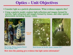
The Swing PierreAuguste Renoir Oil on canvas 1876 How does this painting give evidence that light carries information click for applet Consider light as a particle phenomenon What evidence supports this ID: 1032004
Download Presentation The PPT/PDF document "Optics – Unit Objectives" is the property of its rightful owner. Permission is granted to download and print the materials on this web site for personal, non-commercial use only, and to display it on your personal computer provided you do not modify the materials and that you retain all copyright notices contained in the materials. By downloading content from our website, you accept the terms of this agreement.


1. Optics – Unit ObjectivesThe Swing, Pierre-Auguste Renoir Oil on canvas, 1876How does this painting give evidence that light carries information?click forapplet• Consider light as a particle phenomenon. What evidence supports this?• Using a particle model, explore light reflection and images formed by mirrors, light refraction and images formed by lenses, and other optical phenomena including human vision.Real Alcázar de Sevilla, Spain, summer 2017
2. Reflection of Lightspecular vs. diffuse animationLight particles reflect in a predictable way - like a tennis ball or billiard ball - where the incident angle is equal to the reflected angle.SPECULAR SUNRISESEMI-DIFFUSE SUNSETLight obeys the Law of Reflection but the surface irregularities (compared to “size” of photons) determine whether the reflection is specular or diffuse.LAW OF REFECTIONincidentangleincidentangleReflected light may form a clear image if “regular reflection” occurs where rays maintain orientation.SPECULARDIFFUSEDIFFUSE REFLECTION UP CLOSE
3. Mirrors and Reflection of LightPlane Mirror ConclusionsApparent path length of light equals actual path length of light (this explains why object/image heights equal)Image size is the same as the object, therefore heights are equal, ho = hiImage orientation seems inverted horizontally (left/right), but is not.Incident angle equals reflected angle. Law of Reflection means θi = θrImage location (or distance) equals object distance, do = diImage type is virtual. This image is behind the mirror.babies in mirror videohohidodiPhysics Girl Video on Mirror Images
4. mirrorobjecteyeimageeyeθrθiVirtual ImagesA virtual image is formed when apparent rays diverge from a point.For a mirror, a virtual image will form behind the mirror, and it is upright.A virtual image cannot be cast onto a surface (rays do not converge), but is seen with the eye.TPC animationO Physics simulationTOP VIEWSIDE VIEW
5. Real ImagesA real image is formed when actual rays converge to a point.For a mirror, a real image will form in front of the mirror, and it is inverted.A real image often appears on a surface, and then seen with the eye, but can also be viewed in a mirror.(A virtual image is only seen in a mirror)real imagevirtualimageWhich image is real? Which is virtual? How do you know?Spoon Physics!
6. Curved MirrorsCONCAVE MIRRORCONVEX MIRRORf = focal length r = 2f = radius of curvatureF = focus (or focal pt.) C = center of curvatureREAL FOCUSVIRTUAL FOCUSSolarCookerSecurityMirror
7. Light that reflects off a spherical mirror will not focus clearly. Often the mirror edge shows a blurry image. This is spherical aberration.SPHERICAL MIRRORPARABOLIC MIRRORSpherical AberrationA smaller mirror minimizes spherical aberration.A parabolic mirror eliminates spherical aberration.SPHERICAL ABERRATIONSurendranath simulation
8. Ray Diagrams - MirrorsPrincipal RaysAn incident ray parallel to the principal axis, reflects back through, or from, the focal point.An incident ray through, from, or towards the focal point, reflects back parallel to the principal axis.An incident ray through, from, or towards the center of curvature, reflects back along itself.Surendranath simulation
9. Mirror & Magnification Equation, Sign ConventionsNote: magnification sign does not indicate image size. If |M| < 1 image is smaller, |M| > 1 image is larger.Sign conventions PositiveNegativeobject distanceimage distancefocal lengthmirror typeimage heightmagnificationREAL object, in front of mirrorVIRTUAL objectREAL image, in front of mirrorVIRTUAL image, behind mirrorREAL focus, in front of mirrorVIRTUAL focus, behind mirrorCONVERGING or CONCAVEDIVERGING or CONVEXUPRIGHTINVERTEDUPRIGHTINVERTEDMagnification equation Mirror equation
10. Examples: Mirror & Magnification EquationReal image from Curved Mirror LabVirtual image from Curved Mirror LabRepeat these calculations for a convex mirror with the same radius of curvature
11. anywherevirtualsameuprightbehind mirror| di | = dobetween mirror and Fvirtuallargeruprightbehind mirror| di | > dobetweenF and Creallargerinvertedin front, beyond Cdi > doat Crealsameinvertedin front, at Cdi = dobeyond Crealsmallerinvertedin front, btw F & Cdi < doanywherevirtualsmalleruprightbehind mirror| di | < doMirror SummaryO Physics ray diagram review