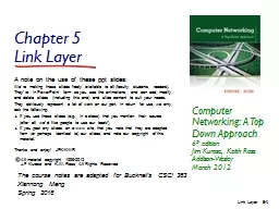
/
Data Link Layer     Computer Networks Data Link Layer     Computer Networks

Data Link Layer Computer Networks - PowerPoint Presentation

yoshiko-marsland
yoshiko-marsland . @yoshiko-marsland
Follow
387 views
Uploaded On 2018-09-22

Data Link Layer Computer Networks - PPT Presentation

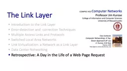
Data Link Layer Outline Parallelism between Transport and Data Link Layer Tanenbaums TreatmentModel of Data Link Layer Protocol 1 Utopia Protocol 2 StopandWait Protocol 3 Positive Acknowledgment with Retransmission ID: 675024

data layer frame link layer data link frame networks computer ack window frames protocol sequence sliding amp receiver event time numbers sender

Share:

Link:

Embed:

Download Presentation from below link

Download Presentation The PPT/PDF document "Data Link Layer Computer Networks" is the property of its rightful owner. Permission is granted to download and print the materials on this web site for personal, non-commercial use only, and to display it on your personal computer provided you do not modify the materials and that you retain all copyright notices contained in the materials. By downloading content from our website, you accept the terms of this agreement.


Presentation Transcript

Slide1

Data Link Layer

Computer Networks Slide2

Data Link Layer OutlineParallelism between Transport and Data Link LayerTanenbaum’s Treatment/Model of Data Link LayerProtocol 1: UtopiaProtocol 2: Stop-and-WaitProtocol 3: Positive Acknowledgment with Retransmission [PAR]Old ‘flawed’ versionNewer version2Computer Networks Data Link LayerSlide3

DL Layer Outline (cont)Pipelining and Sliding WindowsProtocol 4: One Bit Sliding WindowProtocol 5: Go Back NProtocol 6: Selective RepeatFurther Details and Decisions 3Computer Networks Data Link LayerSlide4

12

3

4

5

Data

Data

Data

ACK/NAK

Data

1

2

3

4

5

Data

Data

Data

Data

ACK/NAK

ACK/NAK

ACK/NAK

ACK/NAK

End to End

Hop by Hop

Transport Layer

Leon-Garcia &

Widjaja

:

Communication

Networks

Data Link Layer

Reliable Protocols at Two Layers

4

Computer Networks

Data Link LayerSlide5

Data Link Layer ProtocolsTo achieve control when sending data, a layer of logic, the Data Link Layer protocol is added above the Physical layer.To manage data exchange over a link, DL layer protocol needs:frame synchronizationflow controlerror controladdressingcontrol and data

link management

DCC

9

th

Ed.

Stallings

5

Computer Networks

Data Link LayerSlide6

Data Link LayerProvides a well-defined service interface to the network layer.Determines how the bits of the physical layer are grouped into frames (framing).Deals with transmission errors (CRC and ARQ).Regulates the flow of frames.Performs general link layer management.6Computer Networks Data Link LayerSlide7

Tanenbaum’s DL Layer TreatmentConcerned with communication between two adjacent nodes in the subnet (node to node).Assumptions:The bits are delivered in the order sent.A rigid interface between the Host and the node  the communications policy and the Host protocol (with OS effects) can evolve separately. He uses a simplified model.

7

Computer Networks

Data Link LayerSlide8

HostAHostBLayer 4Node2

Node

1

Layer 2

frame

Tanenbaum’s Data Link Layer Model

Assume the sending Host has

infinite

supply of messages.

A node constructs a

frame

from a

single packet

message

.

The

CRC

is automatically appended in the hardware.

The protocols are developed in increasing complexity to help

students understand the data link layer issues.

Tanenbaum’s

‘Simplified’ Model

8

Computer Networks

Data Link LayerSlide9

Packet sequence

Error-free

packet

sequence

Information

frames

Control frames

Transmitter

Receiver

CRC

Information

packet

Header

Station A

Station B

Information Frame

Control frame

CRC

Header

Basic Elements of ARQ

Leon-Garcia &

Widjaja

:

Communication

Networks

9

Computer Networks

Data Link LayerSlide10

Tanenbaum’s Protocol DefinitionsContinued Figure 3-9. Some definitions needed in the protocols to follow. These are located in the file protocol.h.

10

Computer Networks

Data Link LayerSlide11

ackseqkindinfobuffer

physical layer

network layer

data link layer

frame

packet

Packet and Frame Definitions

preamble

postamble

CRC

11

Computer Networks

Data Link LayerSlide12

Protocol Definitions(continued)Figure 3-9. Some definitions needed in the protocols to follow. These are located in the file protocol.h.12Computer Networks

Data Link LayerSlide13

Figure 3-10Unrestricted Simplex Protocol13Computer Networks Data Link LayerSlide14

Figure 3-11Simplex Stop-and-Wait Protocol14Computer Networks Data Link LayerSlide15

Stop-and-Wait ScenariosFigure 2.17 Timeline showing four different scenarios for the stop-and-wait algorithm.(a) The ACK is received before the timer expires; (b) the original frame is lost; (c) theACK is lost; (d) the timeout fires too soon {premature timeout!!}

Now we introduce

a

noisy channel

i

nto

our world!

15

P&D

Computer Networks

Data Link LayerSlide16

(a) Frame 1 lost A B

frame

0

frame

1

ACK

frame

1

ACK

time

Time-out

frame

2

(b) ACK lost

A

B

frame

0

frame

1

ACK

frame

1

ACK

time

Time-out

frame

2

ACK

In parts (a) and (b) transmitting station A acts the same way, but part (b) receiving station B accepts frame 1 twice.

Stop-and-Wait [with errors]

without sequence numbers

ambiguous results !!

16

Computer Networks

Data Link LayerSlide17

Protocol 3: Positive Acknowledgementwith Retransmissions [PAR] Introduce Noisy ChannelsThis produces:Damaged and lost framesDamaged and lost ACKsPAR ProtocolTools and issues:

Timers

Sequence numbers

Duplicate frames

17

Computer Networks

Data Link LayerSlide18

#define MAX_SEQ 1typedef enum {frame_arrival, cksum_err, timeout} event_type;include “protocol.h”void sender_par (void){ seq_nr next_frame_to_send;

frame s;

packet buffer;

event_type

event;

next_frame_to_send

= 0;

from_network_layer

(&buffer);

while (true)

{

s.info = buffer;

s.seq

=

next_frame_to_send

;

to_physical_layer (&s);

start_timer (s.seq); wait_for_event (&event);

if (event == frame_arrival) {

stop_timer (s.seq);

from_network_layer (&buffer);

inc (next_frame_to_send);

} }

}Protocol 3

Positive ACK with Retransmission (PAR) [Old Tanenbaum Version]

18Computer Networks

Data Link LayerSlide19

void receiver_par (void){ seq_nr next_frame_to_send; frame r, s; event_type event; frame_expected = 0; while (true) { wait_for_event

(&event);

if (event ==

frame_arrival

)

{

from_physical_layer

(&r);

if (

r.seq

==

frame_expected

)

{

to_network_layer(&r.info);

inc (frame_expected);

} to_physical_layer (&s);

}

}}

/* Note – no sequence number on ACK */

Protocol 3 Positive ACK with Retransmission (PAR) [Old

Tanenbaum Version]19

Computer Networks Data Link LayerSlide20

AB

frame

0

frame

0

ACK

frame

1

ACK

time

premature

time-out

frame

2

Transmitting station A misinterprets duplicate ACKs.

 This protocol is broken !!

PAR

[OLD]

problem

Ambiguities

occur when

ACKs

are

not

numbered.

Leon-Garcia &

Widjaja

:

Communication

Networks

20

Computer Networks

Data Link LayerSlide21

PARSimplex Protocol for a Noisy ChannelFigure 3-12.A Positive Acknowledgement with Retransmission protocol.

Continued

Code

added

21

Computer Networks

Data Link LayerSlide22

A Simplex Protocol for a Noisy Channel Figure 3-12.A Positive Acknowledgement with Retransmission protocol.Code

added

22

Computer Networks

Data Link LayerSlide23

Transmitter

Receiver

S

last

R

next

0 1

0 1

0 1

0 1

0 1

0 1

0 1

0 1

(0,0)

(0,1)

(1,0)

(1,1)

Timer

Global State:

(S

last

, R

next

)

Error-free frame 0

arrives at receiver

ACK for

frame 0

arrives at

transmitter

ACK for

frame 1

arrives at

transmitter

Error-free frame 1

arrives at receiver

Station A

Station B

R

next

S

last

23

FSM’s used

t

o

check logic

on both

e

nds of a protocol.

State Machine for Stop-and-Wait

Computer Networks

Data Link LayerSlide24

Pipelined Protocolspipelining:: sender allows multiple, “in-flight”, yet-to-be-acknowledged packetsrange of sequence numbers must be increasedbuffering at sender and/or receiverTwo generic forms of pipelined protocols: Go Back N, Selective Repeat

24

Computer Networks

Data Link Layer

K & RSlide25

Sliding Window Protocols [Tanen]Must be able to transmit data in both directions.Choices for utilization of the reverse channel:mix DATA frames with ACK frames.Piggyback the ACKReceiver waits for DATA traffic in the opposite direction.Use the ACK field in the frame header to send the sequence number of frame being

ACKed

.

 better use of the channel capacity.

25

Computer Networks

Data Link LayerSlide26

Sliding Window ProtocolsACKs introduce a new issue – how long does receiver wait before sending ONLY an ACK frame? Now we need an ACKTimer !! The sender timeout period needs to be set longer.The protocol must deal with the premature timeout problem and be “robust” under pathological conditions.

26

Computer Networks

Data Link LayerSlide27

Sliding Window ProtocolsEach outbound frame must contain a sequence number. With n bits for the sequence number field, maxseq = 2n –

1

and the numbers range from

0

to

maxseq

.

Sliding window::

the sender has a

window

of frames and maintains a list of consecutive sequence numbers for frames that it is permitted to send without waiting for ACKs.

27

Computer Networks

Data Link LayerSlide28

Sliding Window ProtocolsThe receiver has a window of frames that has space for frames whose sequence numbers are in the range of frame sequence numbers it is permitted to accept.Note – sending and receiving windows do NOT have to be the same size.The windows can be fixed size or dynamically growing and shrinking (e.g., TCP uses dynamic cwnd).

28

Computer Networks

Data Link LayerSlide29

Sliding Window ProtocolsThe Host is oblivious to sliding windows and the message order at the transport layer is maintained.sender’s DL window :: holds frames sent but not yet ACKed.new packets from the Host cause the upper edge inside the sender’s window to be incremented.acknowledged frames from the receiver cause the lower edge inside the sender’s window to be incremented.

29

Computer Networks

Data Link LayerSlide30

Sliding Window ProtocolsAll frames in the sender’s window must be saved for possible retransmission and we need one timer per frame in the window.If the maximum sender window size is B, the sender needs at least B buffers.If the sender’s window gets full (i.e., it reaches the maximum window size, the protocol must shut off the Host (the network layer) until buffers become available.

30

Computer Networks

Data Link LayerSlide31

Sliding Window DiagramDCC 9th Ed.Stallings

31

Computer Networks

Data Link LayerSlide32

Sliding Window Protocolsreceiver’s DL windowFrames received with sequence numbers outside the receiver’s window are not accepted.The receiver’s window size is normally static.The set of acceptable sequence numbers is rotated as “acceptable” frames arrive.If a receiver’s window size = 1, then the protocol only

accepts frames

in order

.

This scheme is referred to as

Go Back N

.

32

Computer Networks

Data Link LayerSlide33

Sliding Window ProtocolsSelective Repeat :: receiver’s window size > 1.The receiver stores all correct frames within the acceptable window range.Either the sender times out and resends the missing frame, orSelective repeat receiver sends a NACK frame back the sender.

33

Computer Networks

Data Link LayerSlide34

The ACK sequence number indicates the last frame successfully received.- OR -2. ACK sequence number indicates the next frame the receiver expects to receive.Both schemes

can be strictly individual ACKs or represent cumulative ACKs

.

Cumulative ACKs

is the most common technique used.

Choices in ACK Mechanisms

34

Computer Networks

Data Link LayerSlide35

One-BitSlidingWindowProtocol

35

Computer Networks

Data Link LayerSlide36

A B

fr

0

time

fr

1

fr

2

fr

3

fr

4

fr

5

fr

6

fr

3

ACK1

error

Out-of-sequence frames

Go-Back-4:

fr

5

fr

6

fr

4

fr

7

fr

8

fr

9

ACK2

ACK3

ACK4

ACK5

ACK6

ACK7

ACK8

ACK9

ACKing next frame expected

Go Back N

Timeout Occurs for frame 3 !!

4 outstanding frames

so go back 4

Leon-Garcia & Widjaja:

Communication Networks

36

Computer Networks

Data Link LayerSlide37

A B

fr

0

time

fr

1

fr

2

fr

3

fr

4

fr

5

fr

1

fr

2

ACK1

error

Out-of-sequence

frames

Go-Back-7:

fr

4

fr

5

fr

3

fr

6

fr

7

fr

0

NAK1

ACK3

ACK4

ACK5

ACK6

ACK7

ACK2

Transmitter goes back to frame 1

Go Back N

with NAK error recovery

Leon-Garcia & Widjaja:

Communication Networks

37

Computer Networks

Data Link LayerSlide38

38Computer Networks Data Link LayerSlide39

39Computer Networks Data Link LayerSlide40

Sliding Window ExampleDCC 9th Ed.Stallings

40

Computer Networks

Data Link LayerSlide41

A B

fr

0

time

fr

1

fr

2

fr

3

fr

4

fr

5

fr

6

fr

2

ACK1

error

fr

8

fr

9

fr

7

fr

10

fr

11

fr

12

ACK2

NAK2

ACK7

ACK8

ACK9

ACK10

ACK11

ACK12

ACK2

ACK2

ACK2

Selective Repeat

with NAK error recovery

Cumulative ACK

Retransmit only frame 2

41

Computer Networks

Data Link LayerSlide42

42Computer Networks Data Link LayerSlide43

43Computer Networks Data Link LayerSlide44

Data Link Layer SummaryParallelism between Transport and Data Link LayerTanenbaum’s Treatment/Model of Data Link LayerProtocol 1: UtopiaProtocol 2: Stop-and-WaitProtocol 3: Positive Acknowledgment with Retransmission [PAR]Old ‘flawed versionNewer version44Computer Networks Data Link LayerSlide45

DL Layer Summary (cont)Pipelining and Sliding WindowsProtocol 4: One Bit Sliding WindowProtocol 5: Go Back NProtocol 6: Selective RepeatFurther Details and Decisions 45Computer Networks Data Link Layer