

Diagnostic Solution for an HVAC System ECE Team 169 Anthony Bellantoni EE Greg Carmichael EngrPhys Joe Grassi EE Sponsored by Qualtech Systems Inc Advisor Professor ID: 759419
Download Presentation The PPT/PDF document "Real-time Monitoring and" is the property of its rightful owner. Permission is granted to download and print the materials on this web site for personal, non-commercial use only, and to display it on your personal computer provided you do not modify the materials and that you retain all copyright notices contained in the materials. By downloading content from our website, you accept the terms of this agreement.


Slide1
Real-time Monitoring and Diagnostic Solution for an HVAC System
ECE Team 169
Anthony
Bellantoni
(EE)
Greg Carmichael (
EngrPhys
)
Joe
Grassi
(EE
)
Sponsored by:
Qualtech
Systems Inc.
Advisor:
Professor
John
Chandy
Slide2Presentation Outline
•
Project Goals
•
Brief Explanation of
Qualtech
Systems, Inc.
•
Overview of TEAMS Software
• HVAC Explanation
•
Updated and Completed Model
• Overview of
Detecting a Failure
•
Project
Timeline & Budget
• Project Limitations
• Lessons Learned
Slide3Project Goals
•
Fix & Build Upon Previous Incomplete Senior Design
Project
-
Update Diagnostic HVAC Model for ITEB
•
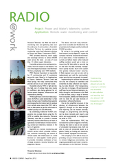
Obtain real-time
data from the building
sensors
- Develop Failure-Detection Code
•
Combine model and code to detect for faults in real-time.
Slide4Qualtech Systems, Inc.
•
Located in East Hartford, Connecticut (Founded in 1993)
• Provide advanced system health management, integrated diagnostics and
telemaintenance
Works on any system
Helps improve equipment productivity
•TEAMS - Testability Engineering and Maintenance System
Slide5TEAMS
Testability Engineering and Maintenance SystemConsists of Multiple ComponentsDesignerRDSRemote Diagnostic ServerRT“Real-Time” Data Collection
http://tomgpalmer.com/wp-content/uploads/legacy-images/FLASH%20LIGHT.jpg
Slide6TEAMS - Designer
Used to create a model of a system, including components with their respective test points
Can be used to model any complex system (e.g.-MRI, Car, Building, etc.)
Slide7TEAMS - RDS
Online Server that connects all components of TEAMS software
Decides Which Component is Most Likely Failing From the Designer
Provides Possible Solutions during Manual Maintenance
Stores information gathered for future analyses
Slide8TEAMS - RT
Provides Diagnostics in
Real-Time
Connects Developed Code with Generated Sensor Values to RDS
Allows for constant connection
Slide9What is HVAC?
H
eating
V
entilation and
A
ir
C
onditioning
Processes Air in a Building, Vehicle, or Other Structure
Maximize Occupant(s) Comfort Of Enclosed Area
Range from “Central Air” in Residential Homes to Complex Multi-Building Systems
Slide10ITE HVAC System
Basement (Heat Exchanger)
Tunnel to COGEN plant
Penthouse (Air Handler)
VAV (Variable Air Volume)
One For Each Room
Measured on Every Floor at Every Point in System
Slide11ITE Penthouse Schematic
Slide12VAV Schematic
Slide13Procedure – ITEB Schematic
Slide143rd Floor Schematics
Slide15Procedure - Designer
Slide16Last Year’s Designer Model
Slide17Our Updated Designer Model
Slide18Slide19Slide20Slide21Procedure - RDS
Slide22RDS Photos
Slide23Procedure – RT
Slide24Slide25Procedure – Detecting Failures
Slide26Failure Detection Code Process
1)
Extract sensor values from text file and determine whether or not a failure is occurring
2)
Export results file into TEAMS-RT
3)
TEAMS-RT combines test results with our model and determines possible failure points
Slide27How to Determine a Failure
Set threshold value for maximum deviation from
set point
Cannot assume failure after one test
Initiate a counter to
determine number
of tests in a row that fail
If consecutive tests trend toward the set point, counter returns to 0
If deviation from the set point is less than the maximum allowed, counter returns to 0
If
n
tests in a row fail and do not approach set point, assume failure
Slide28Failure-Detection Method
Slide29Project Budget
http://i.crn.com/images/free_cloud_400.jpg
http://blog.outreach.com/wp-content/uploads/2011/09/Church-events-on-no-Budget.jpg
http://www.rosemarierealty.com/wp-content/uploads/2012/03/dreamstime_xs_17999966-300x300.jpg
http://static.seekingalpha.com/uploads/2009/3/4/saupload_mar04_09_bm.jpg
Slide30Project Timeline
Task
September
October
November
December
January
February
March
April
Software access
Gather
& Review
Schematics
Research HVAC
Update
TEAMS
Designer M
odel
Learn
C
++ Syntax
Develop
Failure-Detection Code
Merge
Code With
M
odel in SDK and RDS
Test
- Debug - Cleanup
Slide31Final Tasks
Connect our Failure Results with TEAMS RT
Connecting RT with RDS
Slide32Project Limitations
Obtaining access to actual sensor values
Slide33Lessons Learned
TEAMS is capable of modeling large systems
Difficult for beginners and requires expert knowledge to build
HVAC systems are complex
Prepare for setbacks
Information from facilities
Remote server issues
Slide34Questions
?