
Soldering is a process in which two or more metal items are joined together by melting and flowing a filler metal into the joint the filler metal having a lower melting point than the workpiece soldering iron solder parts to solder soldered ID: 673318
Download Presentation The PPT/PDF document "living with the lab Soldering Tips" is the property of its rightful owner. Permission is granted to download and print the materials on this web site for personal, non-commercial use only, and to display it on your personal computer provided you do not modify the materials and that you retain all copyright notices contained in the materials. By downloading content from our website, you accept the terms of this agreement.


Slide1
living with the lab
Soldering Tips
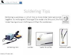
Soldering is a process in which two or more metal items are joined together by melting and flowing a filler metal into the joint, the filler metal having a lower melting point than the workpiece.
soldering iron solder parts to solder soldered parts
© 2011 LWTL faculty teamSlide2
living with the lab
2
The content of this presentation is for informational purposes only and is intended only for students attending Louisiana Tech University.
The author of this information does not make any claims as to the validity or accuracy of the information or methods presented.
The procedures
demonstrated
here
are potentially dangerous and could result in injury or damage. Louisiana Tech University and the State of Louisiana, their officers
, employees, agents or volunteers,
are not liable or responsible for any injuries, illness, damage or losses which may result from your using the materials or ideas, or from your performing the
experiments or procedures depicted in this presentation. If
you do not agree, thendo
not view this content.
DISCLAIMERSlide3
living with the lab
3
safety is covered at the end of this presentation . . . let’s learn about soldering first
. . . please don’t try any of this until you are aware of the safety concerns.Slide4
living with the lab
4
equipment & supplies
soldering iron
(to melt the solder metal)
helping hands soldering aid
safety glasses
workpieces
(photoresistor & wires)
flux
(makes solder flow & stick)
heat shrink insulation
solder
heat gun
(to activate
heat shrink insulation)Slide5
living with the lab
5
C
ut wires to the desired length, stripping off unwanted insulation (¼ inch is good). The wire used for breadboarding is 22 gage, so use the appropriate notch in your wire stripper.
A
pply flux to the parts to be soldered. You can dip the end of the wire into the flux. Flux cleans the surface of the parts to be soldered, making the solder flow and stick.
soldering steps
Globbing
on flux like this will produce fumes; wipe off excess flux. A flux pen may be a cleaner approach. Some fluxes clean up better than others.Slide6
living with the lab
6
Turn on the soldering iron and allow it to reach the set point; common soldering temperatures are 600⁰F for solders containing lead and 700⁰F for lead-free solders. Of course, soldering temperature depends on the melting temperature of the solder you are using. Always use as low a temperature as possible since . . .
high temperatures damage soldering iron tips
excessive temperature can damage electronic components
the flux boils away too quickly, reducing solder bonding to the parts
higher temperatures could result in more severe burns
Clean the tip of the soldering iron by wiping it against the wetted sponge on the stand; repeat occasionally as you solder since it is important to maintain a clean tip.
Melt solder directly onto the tip to “tin” the tip, wiping off excess solder on the sponge until the tip has a shiny
and uniform coating of solder.
soldering stepsSlide7
living with the lab
7
Clamp the part to be soldered into the “helping hands” tool; if you are soldering a wire that is covered with insulation and is several inches long, you can hold the wire in your hand (a few inches away from where you will be soldering).
Bend your solder so that about 1.5 inches of solder is protruding from your roll of solder. With your solder tip pointing
downward
, melt some solder onto the tip of your soldering iron. You should see a small bead of solder on the tip, ready to be deposited onto the workpiece.
soldering steps
depiction of solder on tip of a
vertically oriented soldering iron
(solder will be silver, not red)
bend solder wire so you can safely
melt some onto your tipSlide8
living with the lab
8
The helping hands device improves safety and
allows you to hold parts in the correct position.
Before soldering the parts together, they should first be coated with a thin layer of solder; this process is called “tinning.” Touch the tip of the vertically oriented soldering iron on the area to be soldered. Solder should flow onto the part with a smooth and even coat.
Melt more solder onto the tip if needed and bring the parts to be soldered together in the proper position, touching the solder bead on the vertically oriented tip to the area where solder is needed. Leave the soldering iron in place briefly (about one second) until the solder flows into the joint. Hold the parts together briefly until the solder solidifies.
soldering stepsSlide9
living with the lab
9
appearance of a solder joint
The flux that remains on the soldered surface can be removed if desired by cleaning with an appropriate solvent (water or alcohol are common, depending on the type of flux).Slide10
living with the lab
10
a better way to join wires or leads
While the above procedure is a quick and easy way to join together two wires or leads,
globbing
solder onto the tip of the soldering iron and transferring it to the connection is
coinsidered
a “no-no” by professionals; the flux is boiled away before it has a chance to do it’s job. A more proper set of steps is provided below:C
lean and tin the tip of the soldering iron.
Tin the ends of both wires or leads:
Secure the wire or lead in the helping hands device.Place the tip of the soldering iron below the wire to be tinned.Feed in solder on top of the wire, moving the tip and the melting strand of solder up and down the length of the region to be tinned.
Bend a small hook in each of the two wires/leads.Place the tip of the soldering iron on one side of the connection, and feed in solder from the other side until the joint is soldered.
tinned and bent wires before joining
wires after joining
this melting of the insulation could be
prevented by using a heat sink (shown later)Slide11
living with the lab
11
adding insulation (if desired)
Slip heat shrink over the wires to be insulated; you need to put the heat shrink on
before
you solder the joint together when the jointed parts preclude sliding on the insulation.
Apply heat with the heat gun, heating until the insulation shrinks into place.
slide into positionSlide12
living with the lab
12
adding insulation (if desired)
It is often snazzy to tightly twist the wire together for a more tidy and organized wiring layout. To do this, insert the loose ends of the wires into the chuck of a drill, running the drill until the wire is tightly wound (to suit your taste). When drilling, pinch the wires at the base of the photoresistor together to keep the drill from breaking the wires off the photoresistor.
Trim the loose ends to even them up or to make them the correct length, and strip off about ¼ inch of insulation for use with a breadboard.Slide13
living with the lab
13
prevention of burns and fire
CAUTION
HOT
don’t touch the tip of the soldering iron (could be as high as 400⁰C or 750⁰F)
hold
parts
to be soldered with a “helping hands” device or with a clamp (a vise works
)
never touch a bare metal part being soldered (heat will quickly conduct to your fingers)
the soldering stand and other items that have been in contact with the soldering iron will become hot enough to burn you
always return the soldering iron to the stand
turn off the soldering iron when you are finished
the heat gun can also cause burns – keep skin away from air stream and exit portSlide14
living with the lab
14
protect your eyes
always wear safety glasses when soldering – solder can “spit”
always wear safety glasses when watching somebody else solder
be careful of others around you when soldering; it would be easy to turn and touch somebody with the soldering iron
incompatible
wikipedia.comSlide15
living with the lab
15
solder and flux
most solders contain lead; we recommend that you use lead-free solder
lead is a toxic substance
lead can be absorbed through your skin, or you can draw lead into your body by breathing the fumes given off by soldering
solder in a well-ventilated space; avoid soldering in a small, closed space, regardless of what type of solder you are using
most of the smoke that comes from soldering is due to the flux; these fumes are also unhealthy
wash your hands after soldering
read the warning labels on the solder and flux before useSlide16
living with the lab
16
use common sense
no horseplay in the lab
don’t solder on flammable work surfaces
don’t solder around flammable substances (gasoline, hairspray, . . .)
let your instructor know if you think something is not
safe
know the location of the fire extinguisher and first-aid kit
let your instructor know if you are injuredSlide17
living with the lab
17
solders & temperatures
solder containing lead:
A common tin/lead solder has a composition of 60% tin and 40% lead and melts at 188⁰C or 370⁰F. Lead-based solders melt at a lower temperature and are often considered to be more forgiving (easier to solder and better reliability) than lead-free solders. However, lead-based solders are being phased out due to
environmental
and
health concerns.
lead-free solder:
One popular lead-free solder has a composition of 96%
tin and 4% silver and melts at 221⁰C or 430⁰F (part number 65-026 at radio shack). Tips for lead-free soldering, modified from
http://www.emsnow.com/npps/story.cfm?id=18862, are provided below:
Insure the tips are designed for lead-free soldering
Insure the soldering temperature is set to
700-800°F
Insure
the flux content in the wire is a least 2%
wt/wt
Use
the correct tip for the
job
Insure
the parts are easily solderable with the chosen
flux
Avoid
prolonged contact
times
Avoid
needless reworking of the
joint
Avoid
the use of additional liquid
fluxSlide18
living with the lab
18
tips for through-hole soldering
For through-hole soldering, pins are inserted through the holes in a printed circuit board and then soldered into place.
printed circuit board with unsoldered headers
board after soldering headers into placeSlide19
living with the lab
19
tips for through-hole soldering
Apply flux to the region to be soldered
Touch the base of the pin with the soldering
iron; the tip should contact both the pin
AND
the metal surrounding the
hole
Position the solder at the base of a
pin on the opposite side from the tipAs the solder melts, feed it into the jointFeed in solder until the joint has a concave appearance
feed the solder into the heated joint
from the opposite side of tip
insufficient solder
goodSlide20
living with the lab
20
YouTube videos
There are many videos on YouTube that demonstrate soldering; many of these videos were created by professionals.
Hand Soldering for Through Hole Components (7:06)
http://www.youtube.com/watch?v=x0YxEilyQVY&NR=1
Lead Free Through Hole Soldering Tips | B.E.S.T. Corporation (4:17)
http://www.youtube.com/watch?v=CGnt2vCAjfQSlide21
living with the lab
21
soldering accessories
heat sink clamp
– you can use a clamp like this to protect electronic components from damage during soldering; place clamp between where you are soldering and the component; needle nose pliers also work well
solder sucker
– when you make a mistake when soldering onto a printed circuit board, a solder sucker can be used to remove unwanted solder; heat up solder first, and then suck it out
examples of soldering on printed circuit boards
Mathew Newton, wikipedia.com