
INTRODUCTION OF (EN) ISO 8100-1/2:2026 Main
BR
Published · 141 slides · 0 views

1 / 1








Description
INTRODUCTION OF (EN) ISO 8100-12:2026 Main differences in comparison with EN 81-2050:2020 Overview of key updates, structural changes and technical clarifications 2026 European Elevator Association (EEA) European Lift Association
Related Topics
Share
Embed code
Download this presentation From Below
"INTRODUCTION OF (EN) ISO 8100-1/2:2026 Main" is the property of its rightful owner. Permission is granted to download and print the materials on this website for personal, non-commercial use only, and to display it on your personal computer provided you do not modify the materials and that you retain all copyright notices contained in the materials. By downloading content from our website, you accept the terms of this agreement.
Presentation Transcript
01
INTRODUCTION OF (EN) ISO 8100-1/2:2026
Main differences in comparison with
EN 81-20/50:2020
Overview of key updates, structural changes and technical clarifications © 2026 European Elevator Association (EEA) / European Lift Association (ELA) - All rights reserved.
Disclaimer: The present document is for general information purposes only and should not be construed as legal advice. It does not have any binding effect on any of the EEA or ELA members or on any other party. It is not intended as a substitute for each stakeholder’s own assessment and decision making. EEA and ELA decline any and all liability for any measure taken or not taken on the basis of the present document.<br>
02
Disclaimer The purpose of this document is to outline and introduce the main changes applied to (EN) ISO 8100-1:2026 and (EN) ISO 8100-2:2026 standards.
While parts of the referred (EN) ISO 8100-1:2026 and (EN) ISO 8100-2:2026 standards may be quoted in the text of this document (acc. CEN and ISO rules), this document is purely designed as a supportive tool to allow readers gain a deeper understanding of the changes in the standards.
The present document is for general information purposes only and should not be construed as legal advice. It does not have any binding effect on any of the EEA or ELA members or on any other party. It is not intended as a substitute for each stakeholder’s own assessment and decision making. EEA and ELA decline any and all liability for any measure taken or not taken on the basis of the present document.
Regarding the possibility of translating the document into languages other than the original (English), please consider:
any translated version will have to state that it is a translation into (“language”) from the original EEA/ELA English version and that the translation was made by (“translating entity”) who takes all on all responsibility for the correctness of the translation;
any translated version must be sent to EEA/ELA before release since EEA/ELA need to check that their copyright, disclaimer, logo is there and may want to have a look at the general layout.<br>
03
Acknowledgement This presentation was developed by the European Lift Association and CEN/TC 10/WG 1 as part of the initiative on the introduction of (EN) ISO 8100-1/2:2026.
We sincerely thank the experts of CEN/ TC 10/WG 1 for their valuable technical input and collaborations through the project. Particular thanks to the TF leads and reviewers for their support in analysing and aligning the main changes between EN 81-20/50:2020 and (EN) ISO 8100-1/2:2026.
The consolidated presentation reflects the collaborative efforts and expertise shared across all Task Forces.
The consolidation and coordination of contributions were carried out by Teuvo (Ted) Väntänen and Peipei Wang (VFA-Interlift e.V., Germany).<br>
04
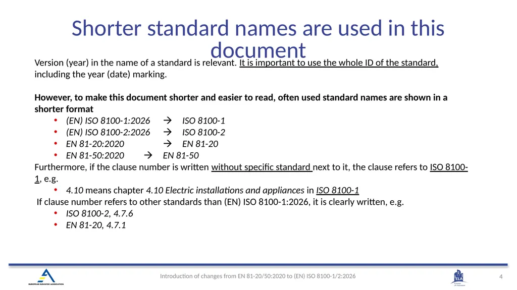
Version (year) in the name of a standard is relevant. It is important to use the whole ID of the standard, including the year (date) marking.
However, to make this document shorter and easier to read, often used standard names are shown in a shorter format
(EN) ISO 8100-1:2026 ISO 8100-1
(EN) ISO 8100-2:2026 ISO 8100-2
EN 81-20:2020 EN 81-20
EN 81-50:2020 EN 81-50
Furthermore, if the clause number is written without specific standard next to it, the clause refers to ISO 8100-1, e.g.
4.10 means chapter 4.10 Electric installations and appliances in ISO 8100-1
If clause number refers to other standards than (EN) ISO 8100-1:2026, it is clearly written, e.g.
ISO 8100-2, 4.7.6
EN 81-20, 4.7.1 Shorter standard names are used in this document<br>
05
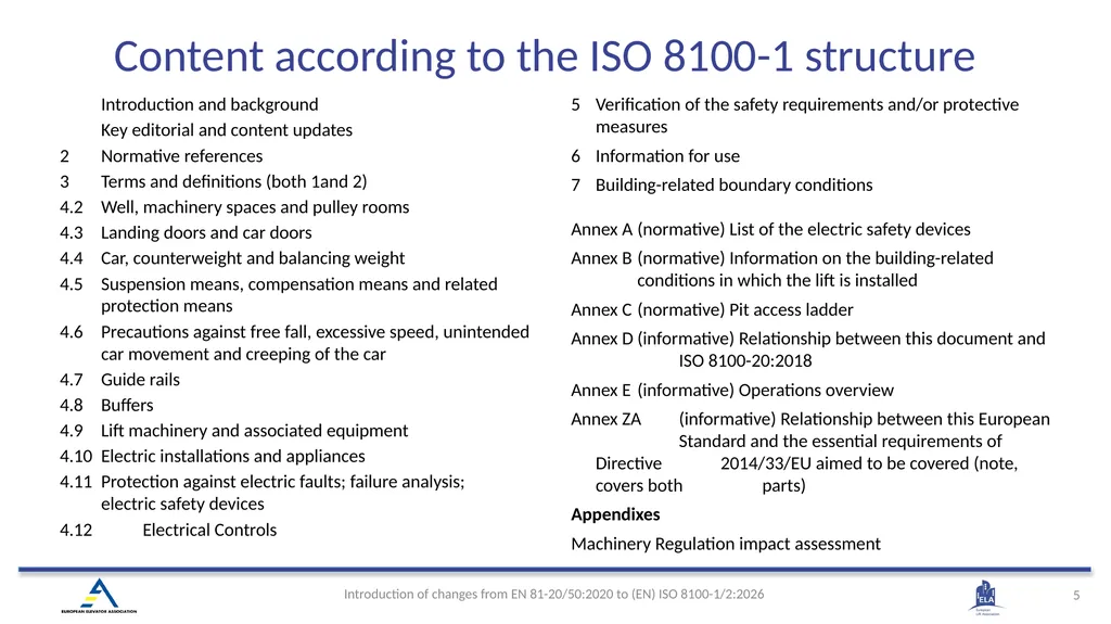
Introduction and background
Key editorial and content updates
2 Normative references
3 Terms and definitions (both 1and 2)
4.2 Well, machinery spaces and pulley rooms
4.3 Landing doors and car doors
4.4 Car, counterweight and balancing weight
4.5 Suspension means, compensation means and related protection means
4.6 Precautions against free fall, excessive speed, unintended car movement and creeping of the car
4.7 Guide rails
4.8 Buffers
4.9 Lift machinery and associated equipment
4.10 Electric installations and appliances
4.11 Protection against electric faults; failure analysis; electric safety devices
4.12 Electrical Controls
5 Verification of the safety requirements and/or protective measures
6 Information for use
7 Building-related boundary conditions
Annex A (normative) List of the electric safety devices
Annex B (normative) Information on the building-related conditions in which the lift is installed
Annex C (normative) Pit access ladder
Annex D (informative) Relationship between this document and ISO 8100-20:2018
Annex E (informative) Operations overview
Annex ZA (informative) Relationship between this European Standard and the essential requirements of Directive 2014/33/EU aimed to be covered (note, covers both parts)
Appendixes
Machinery Regulation impact assessment Content according to the ISO 8100-1 structure<br>
06
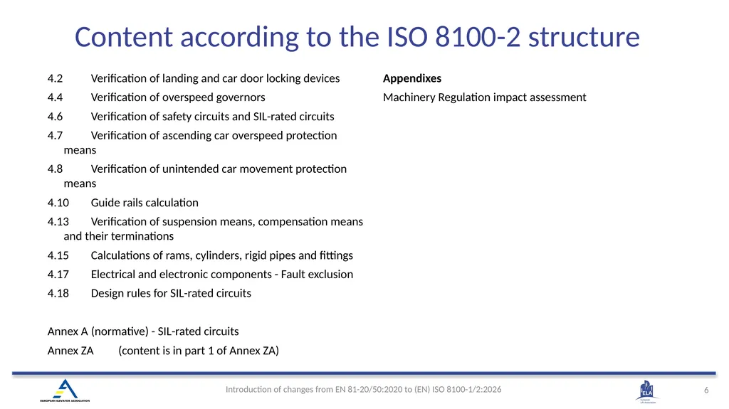
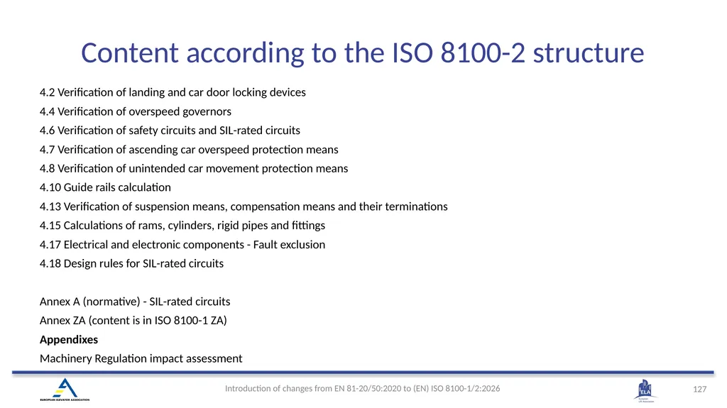
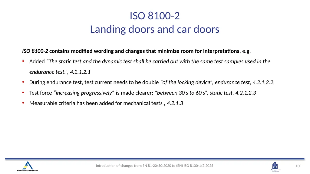
4.2 Verification of landing and car door locking devices
4.4 Verification of overspeed governors
4.6 Verification of safety circuits and SIL-rated circuits
4.7 Verification of ascending car overspeed protection means
4.8 Verification of unintended car movement protection means
4.10 Guide rails calculation
4.13 Verification of suspension means, compensation means and their terminations
4.15 Calculations of rams, cylinders, rigid pipes and fittings
4.17 Electrical and electronic components - Fault exclusion
4.18 Design rules for SIL-rated circuits
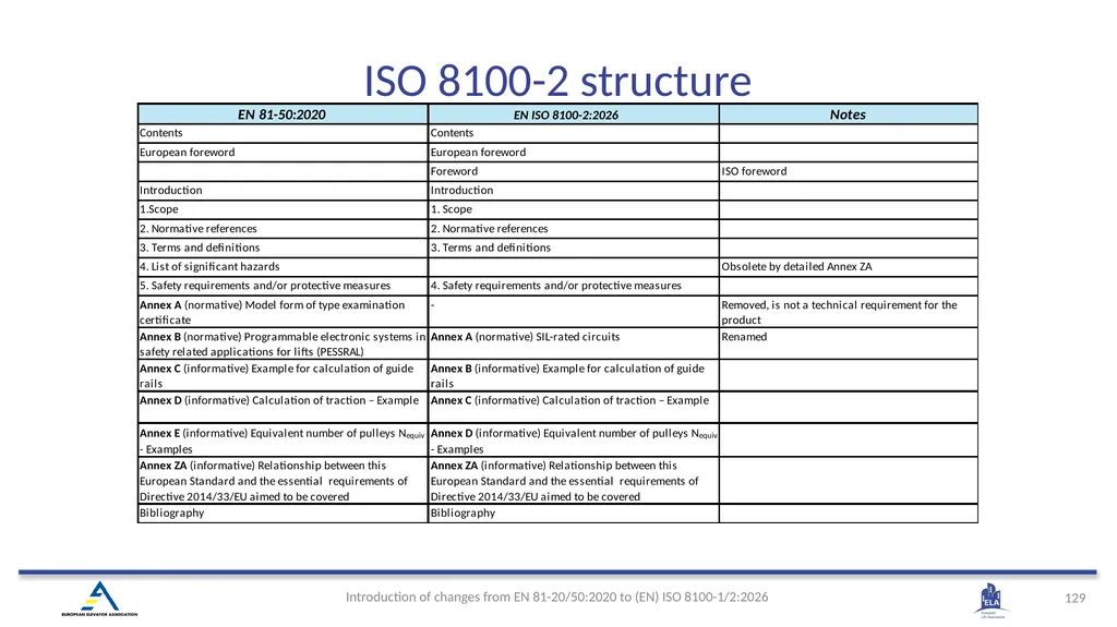
Annex A (normative) - SIL-rated circuits
Annex ZA (content is in part 1 of Annex ZA)
Appendixes
Machinery Regulation impact assessment Content according to the ISO 8100-2 structure<br>
07
(EN) ISO 8100-1:2026 Introduction and Background<br>
08
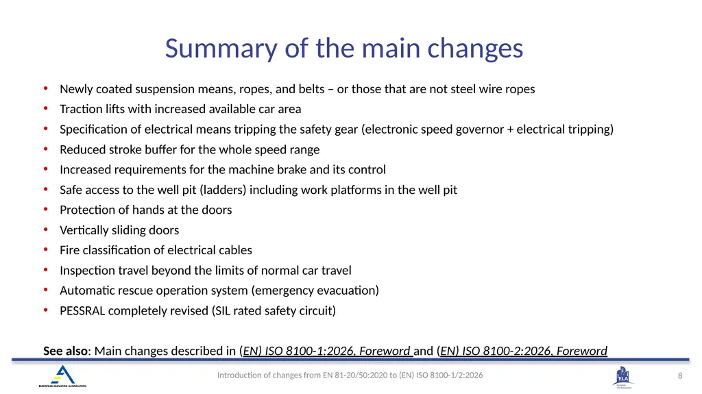
Summary of the main changes Newly coated suspension means, ropes, and belts – or those that are not steel wire ropes
Traction lifts with increased available car area
Specification of electrical means tripping the safety gear (electronic speed governor + electrical tripping)
Reduced stroke buffer for the whole speed range
Increased requirements for the machine brake and its control
Safe access to the well pit (ladders) including work platforms in the well pit
Protection of hands at the doors
Vertically sliding doors
Fire classification of electrical cables
Inspection travel beyond the limits of normal car travel
Automatic rescue operation system (emergency evacuation)
PESSRAL completely revised (SIL rated safety circuit)
See also: Main changes described in (EN) ISO 8100-1:2026, Foreword and (EN) ISO 8100-2:2026, Foreword<br>
09
ISO 8100‑1/2:2026 publication schedule
ISO publication is expected by March 2026
EU transition and applicability
CEN will publish the standard at the same time as EN ISO 8100‑1/2:2026. Transition period will be 36 months after which the EN 81-20/50:2020 standards will be withdrawn (Date of Withdrawal) by CEN.
After EN ISO 8100‑1/2:2026 citation in the Official Journal of EU (OJEU), that is expected during 2026, both EN 81‑20/50:2020 and EN ISO 8100‑1/2:2026 give presumption of conformity to Lifts Directive 2014/33/EU for those EHSRs which are covered by those standards in their Annex ZA.
From January 2027 lift installer needs to show conformance to the new and changed EHSRs of MR, which are already covered in the EN ISO 8100‑1/2:2026.
After Date of Withdrawal only EN ISO 8100‑1/2:2026 will be valid in the EU. Introduction & Background<br>
10
(EN) ISO 8100-1:2026 Key editorial and content updates<br>
11
The (EN) ISO 8100-1:2026 and (EN) ISO 8100-2:2026 standards were jointly prepared by the Technical Committee CEN/TC 10 and the Technical Committee ISO/TC 178 to ensure a set of globally agreed and aligned standards.
Both standards have been re-structured as per ISO/IEC directives Part 2, improving the technical requirements and removing ambiguity, i.e. use of expressions / verbs like “can”, “may”, “should” and instead using “shall” to give clear and concise requirements.
The standards were further reworked to improve the use of, and safety of, lifts for maintenance and installation personnel, customers, owners and end users. Examples:
Requirements for automatic rescue operation have been added, and requirements for emergency operation revised
Requirements to avoid the dragging of hands in doors have been extended
Requirements for cybersecurity have been added
SIL levels of the electric safety devices (Annex A) have been revised
None specific lift requirements i.e., building requirements, were removed from the main body of the clauses and moved to a new Annex B - Information on the building-related conditions in which the lift is installed.
The standards have been also updated to include latest available lift technologies. Examples:
Requirements for suspension means other than steel wire ropes have been added
Requirements for tripping the safety gear by electrical means have been added Key editorial and content updates<br>
12
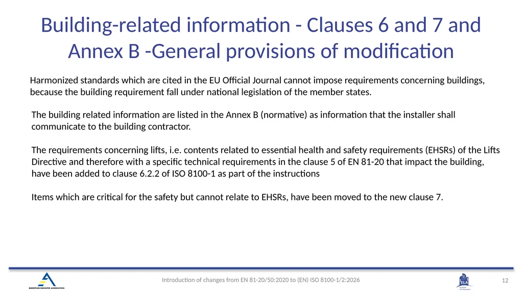
Harmonized standards which are cited in the EU Official Journal cannot impose requirements concerning buildings, because the building requirement fall under national legislation of the member states. The building related information are listed in the Annex B (normative) as information that the installer shall communicate to the building contractor.
The requirements concerning lifts, i.e. contents related to essential health and safety requirements (EHSRs) of the Lifts Directive and therefore with a specific technical requirements in the clause 5 of EN 81-20 that impact the building, have been added to clause 6.2.2 of ISO 8100-1 as part of the instructions
Items which are critical for the safety but cannot relate to EHSRs, have been moved to the new clause 7. Building-related information - Clauses 6 and 7 and Annex B -General provisions of modification<br>
13
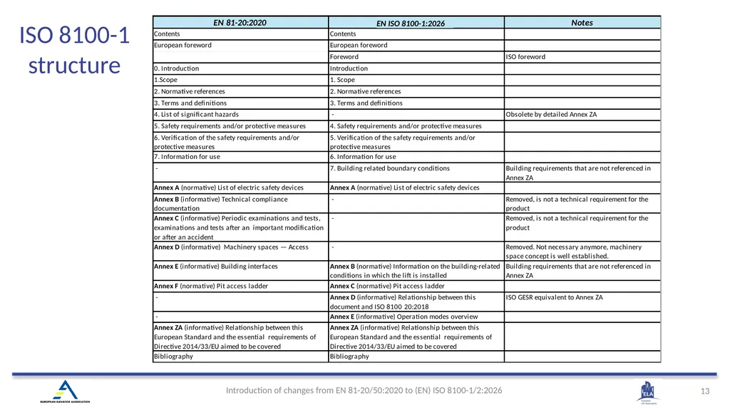
ISO 8100-1 structure<br>
14
(EN) ISO 8100-1:2026 2. Normative References<br>
15
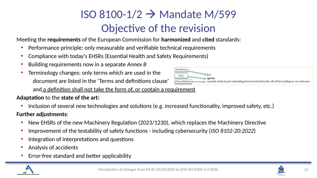
ISO 8100-1/2 Mandate M/599
Objective of the revision Meeting the requirements of the European Commission for harmonized and cited standards:
Performance principle: only measurable and verifiable technical requirements
Compliance with today's EHSRs (Essential Health and Safety Requirements)
Building requirements now in a separate Annex B
Terminology changes: only terms which are used in the
document are listed in the ‘Terms and definitions clause’
and a definition shall not take the form of, or contain a requirement
Adaptation to the state of the art:
Inclusion of several new technologies and solutions (e.g. increased functionality, improved safety, etc.)
Further adjustments:
New EHSRs of the new Machinery Regulation (2023/1230), which replaces the Machinery Directive
Improvement of the testability of safety functions - including cybersecurity (ISO 8102-20:2022)
Integration of interpretations and questions
Analysis of accidents
Error-free standard and better applicability<br>
16
(EN) ISO 8100-1:2026 3. Terms and Definitions<br>
17
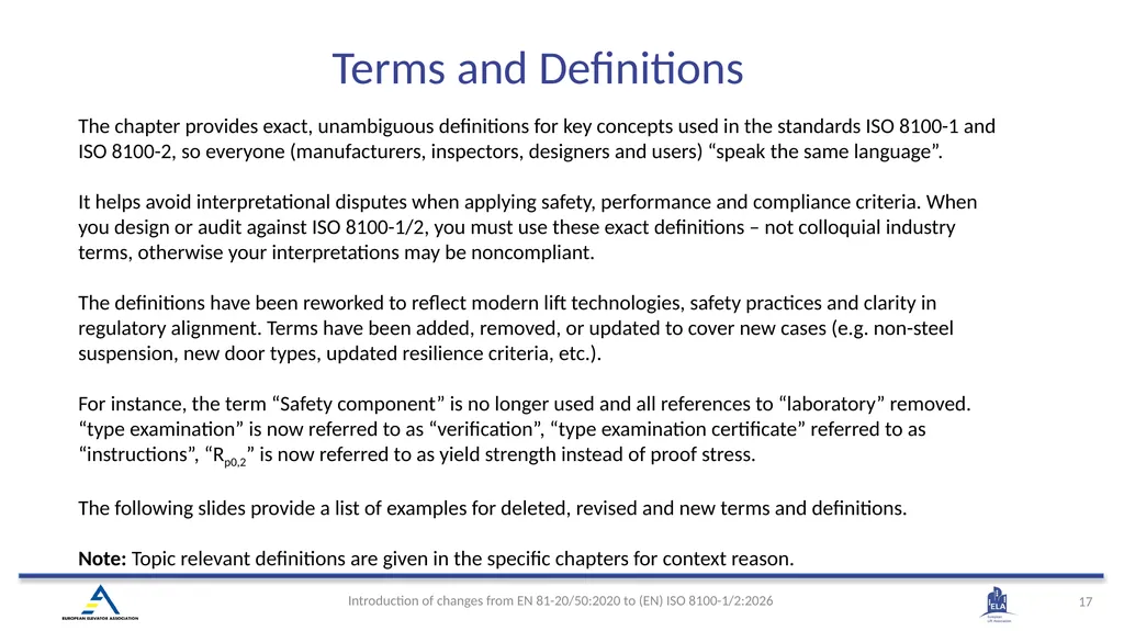
Terms and Definitions The chapter provides exact, unambiguous definitions for key concepts used in the standards ISO 8100-1 and ISO 8100-2, so everyone (manufacturers, inspectors, designers and users) “speak the same language”.
It helps avoid interpretational disputes when applying safety, performance and compliance criteria. When you design or audit against ISO 8100-1/2, you must use these exact definitions – not colloquial industry terms, otherwise your interpretations may be noncompliant.
The definitions have been reworked to reflect modern lift technologies, safety practices and clarity in regulatory alignment. Terms have been added, removed, or updated to cover new cases (e.g. non-steel suspension, new door types, updated resilience criteria, etc.).
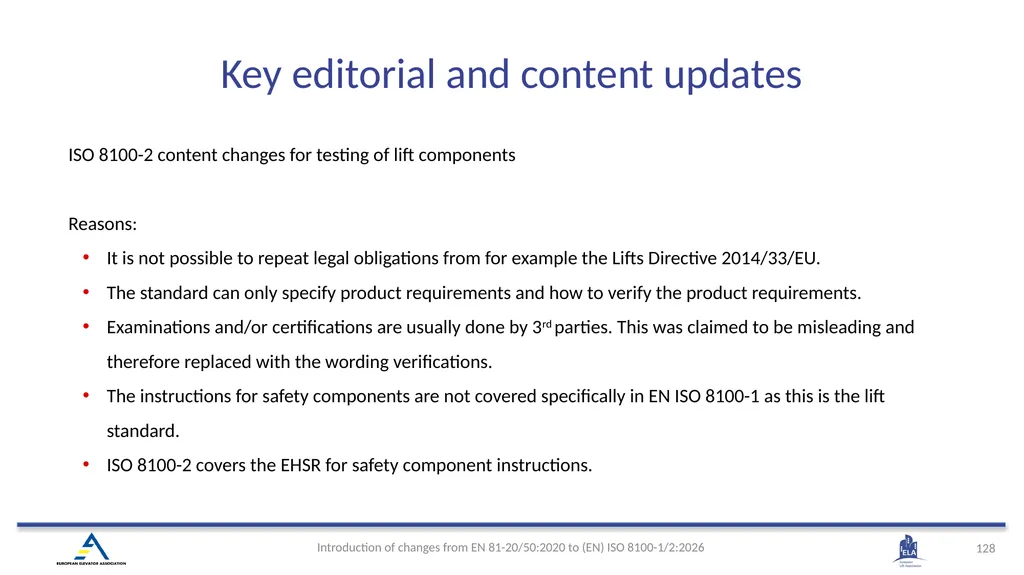
For instance, the term “Safety component” is no longer used and all references to “laboratory” removed. “type examination” is now referred to as “verification”, “type examination certificate” referred to as “instructions”, “Rp0,2” is now referred to as yield strength instead of proof stress.
The following slides provide a list of examples for deleted, revised and new terms and definitions.
Note: Topic relevant definitions are given in the specific chapters for context reason.<br>
18
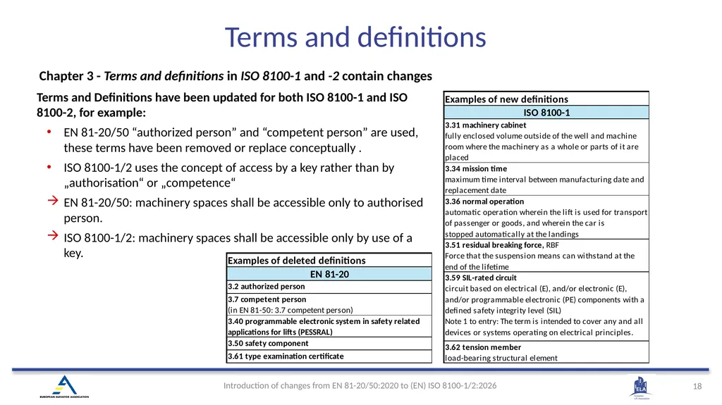
Terms and definitions Chapter 3 - Terms and definitions in ISO 8100-1 and -2 contain changes Terms and Definitions have been updated for both ISO 8100-1 and ISO 8100-2, for example:
EN 81-20/50 “authorized person” and “competent person” are used, these terms have been removed or replace conceptually .
ISO 8100-1/2 uses the concept of access by a key rather than by „authorisation“ or „competence“
EN 81-20/50: machinery spaces shall be accessible only to authorised person.
ISO 8100-1/2: machinery spaces shall be accessible only by use of a key.<br>
19
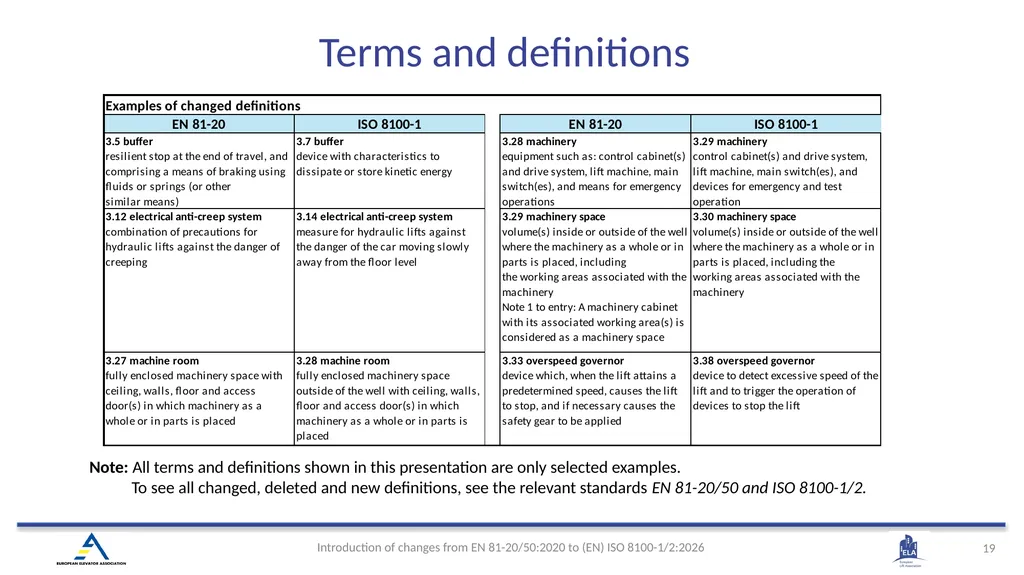
Terms and definitions Note: All terms and definitions shown in this presentation are only selected examples.
To see all changed, deleted and new definitions, see the relevant standards EN 81-20/50 and ISO 8100-1/2.<br>
To see all changed, deleted and new definitions, see the relevant standards EN 81-20/50 and ISO 8100-1/2.<br>
20
authorized person
available car area
competent person
guide rails
installer
laminated glass
PESSRAL
rescue operations
safety component
single acting jack
sling
type examination certificate
unintended car movement Deleted definitions<br>
available car area
competent person
guide rails
installer
laminated glass
PESSRAL
rescue operations
safety component
single acting jack
sling
type examination certificate
unintended car movement Deleted definitions<br>
21
New or modified definitions related to suspension, balancing and lift type carbon fibre reinforced polymer CFRP
material consisting of carbon filaments and resin
minimum breaking force MBF
specified value in kilonewtons below which the measured breaking force is not allowed to fall in a breaking force test
residual breaking force RBF
force that the suspension means can withstand at the end of the lifetime
tension member
load-bearing structural element in an elastomeric coated steel wire rope or traction belt or timing belt
balancing weight
mass which compensates all or part of the mass of the car
counterweight
mass which compensates the mass of the car and part of the rated load
goods passenger lift
passenger lift with additional measures for the transport of goods<br>
22
automatic operation
operation in which start of the movement of the lift happens in response to the momentary actuation of operating devices or in response to any other automatic starting function
normal operation
automatic operation wherein the lift is used for transport of passenger or goods, and wherein the car is stopped automatically at the landings
automatic rescue operation
device or function that operates automatically in case of failure or loss of power supply to move the lift car to a landing
hold-to-run control device
control device which initiates and maintains machine functions only as long as the manual control (actuator) is actuated
mission time
maximum time interval between manufacturing date and replacement date
SIL-rated circuit (replaces PESSRAL)
circuit based on electrical (E), and/or electronic (E), and/or programmable electronic (PE) components with a defined safety integrity level (SIL) New or modified definitions for electrical equipment, controls and operations<br>
23
(EN) ISO 8100-1:2026 4.2 Well, machinery spaces and pulley rooms<br>
24
Access to well (doors, trap doors, ladders)
Pit access and equipment
Refuge spaces (pit and headroom)
Protection (screens, ledges, glazing)
Lighting and services in well Well - overview of main changes<br>
Pit access and equipment
Refuge spaces (pit and headroom)
Protection (screens, ledges, glazing)
Lighting and services in well Well - overview of main changes<br>
25
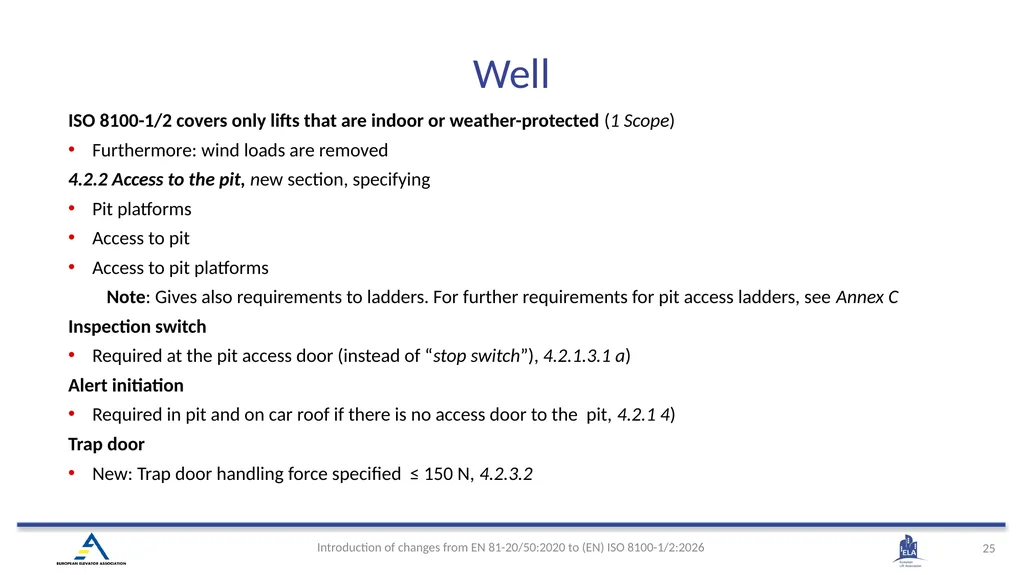
ISO 8100-1/2 covers only lifts that are indoor or weather-protected (1 Scope)
Furthermore: wind loads are removed
4.2.2 Access to the pit, new section, specifying
Pit platforms
Access to pit
Access to pit platforms
Note: Gives also requirements to ladders. For further requirements for pit access ladders, see Annex C
Inspection switch
Required at the pit access door (instead of “stop switch”), 4.2.1.3.1 a)
Alert initiation
Required in pit and on car roof if there is no access door to the pit, 4.2.1 4)
Trap door
New: Trap door handling force specified ≤ 150 N, 4.2.3.2 Well<br>
26
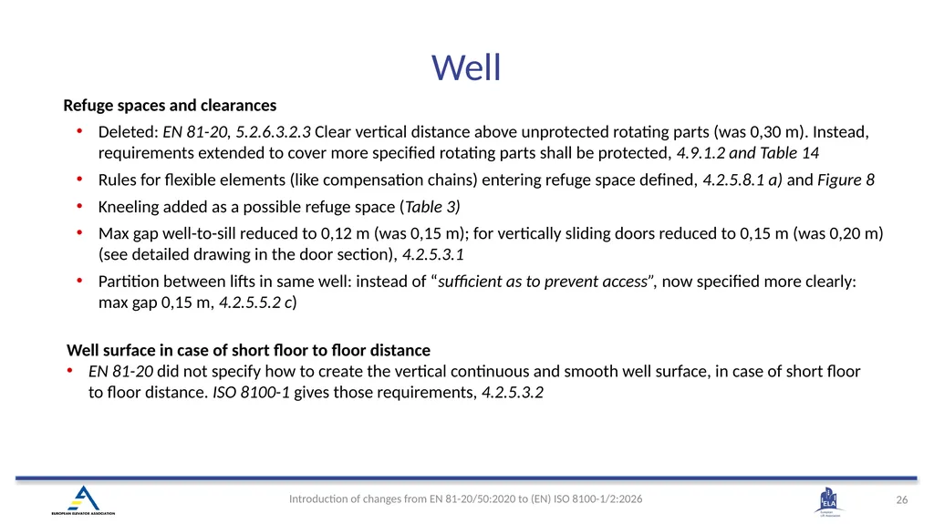
Refuge spaces and clearances
Deleted: EN 81-20, 5.2.6.3.2.3 Clear vertical distance above unprotected rotating parts (was 0,30 m). Instead, requirements extended to cover more specified rotating parts shall be protected, 4.9.1.2 and Table 14
Rules for flexible elements (like compensation chains) entering refuge space defined, 4.2.5.8.1 a) and Figure 8
Kneeling added as a possible refuge space (Table 3)
Max gap well-to-sill reduced to 0,12 m (was 0,15 m); for vertically sliding doors reduced to 0,15 m (was 0,20 m) (see detailed drawing in the door section), 4.2.5.3.1
Partition between lifts in same well: instead of “sufficient as to prevent access”, now specified more clearly: max gap 0,15 m, 4.2.5.5.2 c) Well surface in case of short floor to floor distance
EN 81-20 did not specify how to create the vertical continuous and smooth well surface, in case of short floor to floor distance. ISO 8100-1 gives those requirements, 4.2.5.3.2 Well<br>
27
Luminaire strength
New: Mechanical strength requirements for luminaires has been specified, 4.2.1.2
Requirements are defined in a way that they can be verified (like in many other parts of ISO 8100-1/2), e.g.
Well mechanical strength: “Without permanent deformation” is replaced by ≤ 15 mm elastic deformation and ≤ 1 mm permanent deformation, 4.2.5.2.4
Max opening size in slabs is defined < 150 mm, 4.2.6.3.3 Machinery spaces and access
Clear height for working areas is reduced to 2,0 m (was 2,1 m) (for example 4.2.6.4.2)
Mechanical device to block car movement during maintenance/inspection on the machinery, shall be provided, if uncontrolled car movement is not excluded in the lift’s instructions, 4.2.6.4.3.1, 4.2.6.4.4.1
Manual effort to operate retractable working platform reduced to 150 N (was 250 N), 4.2.6.4.5.4 b) Well<br>
28
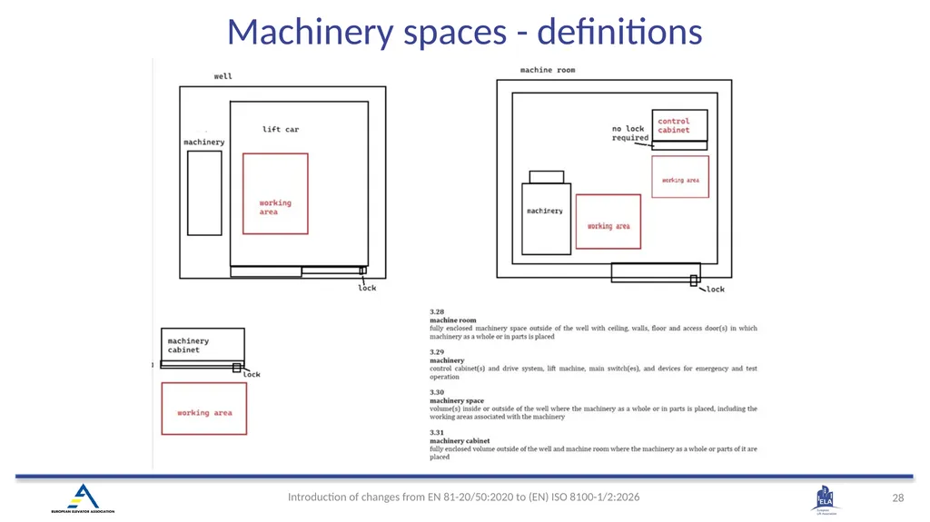
Machinery spaces - definitions<br>
29
(EN) ISO 8100-1:2026 4.3 Landing doors and car doors<br>
30
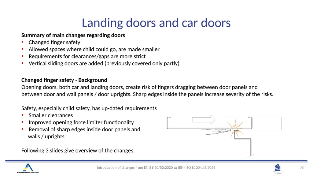
Changed finger safety - Background
Opening doors, both car and landing doors, create risk of fingers dragging between door panels and between door and wall panels / door uprights. Sharp edges inside the panels increase severity of the risks.
Safety, especially child safety, has up-dated requirements
Smaller clearances
Improved opening force limiter functionality
Removal of sharp edges inside door panels and
walls / uprights
Following 3 slides give overview of the changes. Summary of main changes regarding doors
Changed finger safety
Allowed spaces where child could go, are made smaller
Requirements for clearances/gaps are more strict
Vertical sliding doors are added (previously covered only partly) Landing doors and car doors<br>
31
Landing doors and car doors
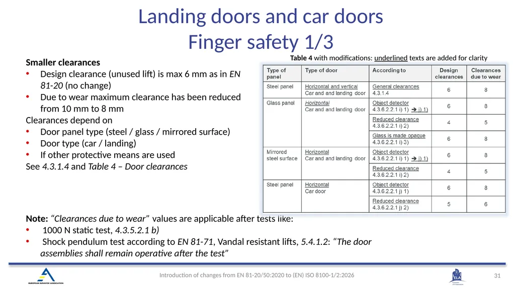
Finger safety 1/3 Smaller clearances
Design clearance (unused lift) is max 6 mm as in EN 81-20 (no change)
Due to wear maximum clearance has been reduced from 10 mm to 8 mm
Clearances depend on
Door panel type (steel / glass / mirrored surface)
Door type (car / landing)
If other protective means are used
See 4.3.1.4 and Table 4 – Door clearances Note: “Clearances due to wear” values are applicable after tests like:
1000 N static test, 4.3.5.2.1 b)
Shock pendulum test according to EN 81-71, Vandal resistant lifts, 5.4.1.2: “The door assemblies shall remain operative after the test” Table 4 with modifications: underlined texts are added for clarity<br>
32
Opening force limiter, 4.3.6.2.2.1 h)
EN 81-20 requires that glass doors have max 150 N opening force limiter
ISO 8100-1 gives 150 N limit to all panel types
Additionally, door movement shall be prevented for at least 20 seconds (door motor torque is removed), 4.3.6.2.2.1 Landing doors and car doors Finger safety 2/3<br>
EN 81-20 requires that glass doors have max 150 N opening force limiter
ISO 8100-1 gives 150 N limit to all panel types
Additionally, door movement shall be prevented for at least 20 seconds (door motor torque is removed), 4.3.6.2.2.1 Landing doors and car doors Finger safety 2/3<br>
33
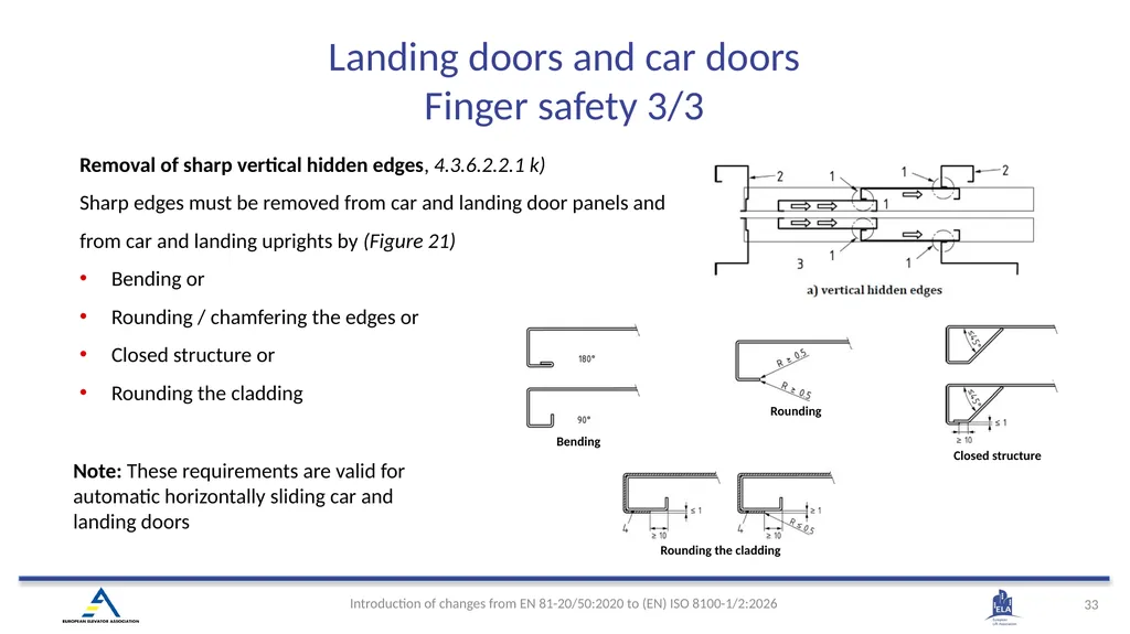
Removal of sharp vertical hidden edges, 4.3.6.2.2.1 k)
Sharp edges must be removed from car and landing door panels and from car and landing uprights by (Figure 21)
Bending or
Rounding / chamfering the edges or
Closed structure or
Rounding the cladding Note: These requirements are valid for automatic horizontally sliding car and landing doors Rounding the cladding Bending Closed structure Rounding Landing doors and car doors Finger safety 3/3<br>
34
Horizontal distance
Distance between
Car door and landing door panels
Door uprights
has been reduced (from 0,12 m and 0,15 m) to 0,10 m (distance l1), 4.3.4.2 and Figure 5 in 4.2.5.3.1 Landing doors and car doors<br>
Distance between
Car door and landing door panels
Door uprights
has been reduced (from 0,12 m and 0,15 m) to 0,10 m (distance l1), 4.3.4.2 and Figure 5 in 4.2.5.3.1 Landing doors and car doors<br>
35
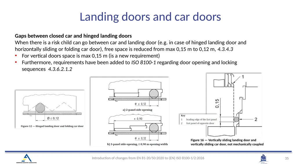
Gaps between closed car and hinged landing doors
When there is a risk child can go between car and landing door (e.g. in case of hinged landing door and horizontally sliding or folding car door), free space is reduced from max 0,15 m to 0,12 m, 4.3.4.3
For vertical doors space is max 0,15 m (is a new requirement)
Furthermore, requirements have been added to ISO 8100-1 regarding door opening and locking sequences 4.3.6.2.1.2 Figure 16 — Vertically sliding landing door and vertically sliding car door, not mechanically coupled Landing doors and car doors<br>
36
Door mechanical strength, 4.3.5.2.2
New requirements have been added, and existing requirements are defined more detailed, e.g.
Retainers need to be metallic, structural part of door panel, secured against self-loosening and marked indicating correct engagement
Folding door are clearly mentioned, requirements being the same as for the horizontal sliding doors
(Note: Vertical sliding door mechanical strength requirements have been added to ISO 8100-1. Table 6, Figure 19.) Glass door markings
Door glass panel marking requirement have been revised and aligned with other lift glass parts, 4.3.5.2.7 Folding doors
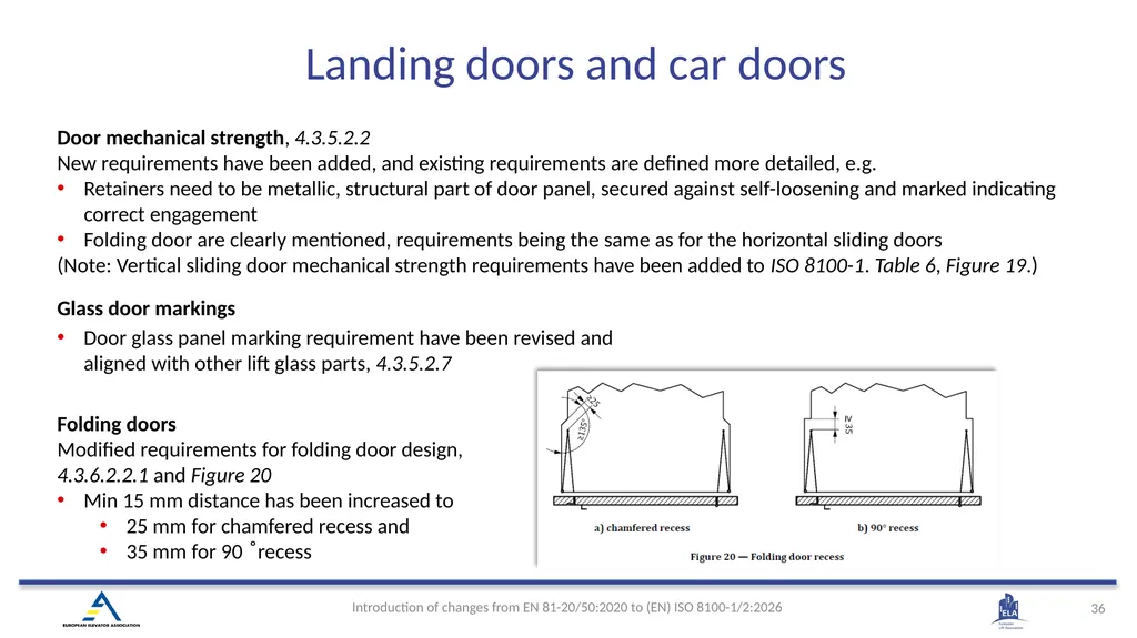
Modified requirements for folding door design, 4.3.6.2.2.1 and Figure 20
Min 15 mm distance has been increased to
25 mm for chamfered recess and
35 mm for 90 ̊ recess Landing doors and car doors<br>
37
Protection against misuse of door locks
Requirement for locking element “shall be protected against deliberate misuse” in EN 81-20 has been defined more clearly:
“straight round object 300 mm long and with a diameter of 1 mm”, 4.3.9.1.1 Definition of the locking device, 4.3.9.1
Clarification what is a locking device has been added:
“Each component specified in 4.3.9, 4.3.10, 4.3.11, 4.3.14 forms part of the locking device.“
Locking element = lock hook / pin + counter part
Locking device = all components which are ensuring the locking of a door (entire railing /top track) Landing doors and car doors<br>
38
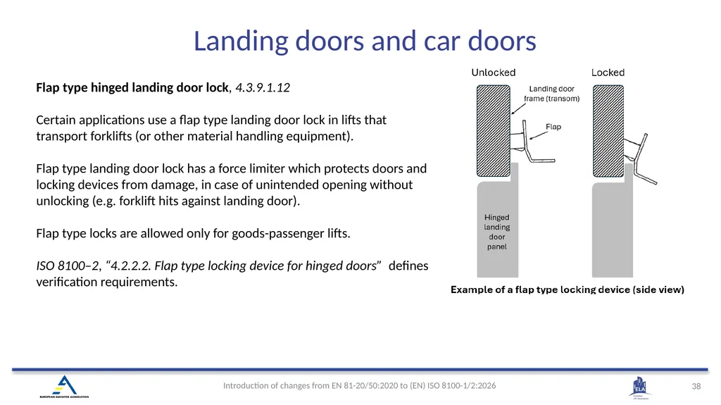
Flap type hinged landing door lock, 4.3.9.1.12
Certain applications use a flap type landing door lock in lifts that transport forklifts (or other material handling equipment).
Flap type landing door lock has a force limiter which protects doors and locking devices from damage, in case of unintended opening without unlocking (e.g. forklift hits against landing door).
Flap type locks are allowed only for goods-passenger lifts.
ISO 8100–2, “4.2.2.2. Flap type locking device for hinged doors” defines verification requirements. Landing doors and car doors<br>
39
Vertical sliding doors, general information
EN 81-20/50 did not give many requirements for vertical doors. To align with North American codes (ASME A17.1/CSA B44), ISO 8100-1 includes typical vertical doors.
Most of the vertical sliding door requirements in ISO 8100-1 are incorporated with other door type requirements. Additionally, 4.3.6.2.3 is vertical door specific.
Vertical doors can only be used for goods passenger lifts
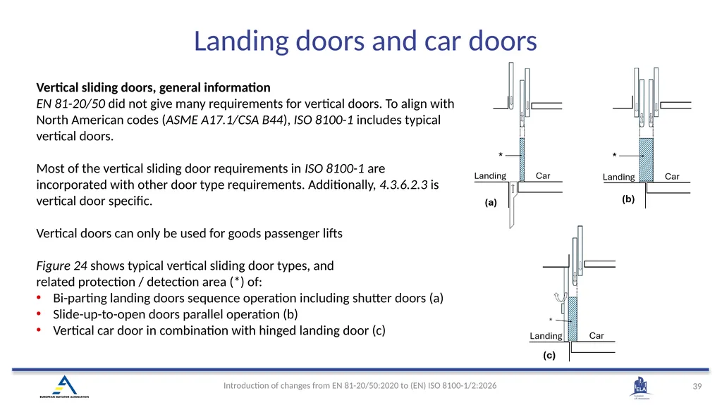
Figure 24 shows typical vertical sliding door types, and
related protection / detection area (*) of:
Bi-parting landing doors sequence operation including shutter doors (a)
Slide-up-to-open doors parallel operation (b)
Vertical car door in combination with hinged landing door (c) Landing doors and car doors<br>
40
(EN) ISO 8100-1:2026 4.4 Car, counterweight and balancing weight<br>
41
Counterweight Clarification on determining car area, 4.4.2.1
Goods passenger lifts include solution for traction and hydraulic, 4.4.2.2
1. Lifts with car being loaded with equipment which is not part of the rated load
2. Lifts with car area bigger than required for the number of persons
Changed requirements for balustrade / car roof floor slip resistance / inspection / emergency lightening, 4.4.6.2, 4.4.7.1, 4.4.10
Updated requirements for counterweight, 4.4.11
Added requirements for non metalic filler bits<br>
42
Changes/Additions:
Special cases for goods-passenger lifts, 4.4.2.2
Bigger car sizes allowed for traction lifts (prev. only hydraulic lifts)
Handling devices not in rated load → downward movement limited ≤ 20 mm by a mechanical device, prevent doors opening before device extended
Overload monitoring before device retraction: SIL 3 (new)
Rated load label at landing, ≥ 50 mm character height, 4.4.2.3.3 Car - Area & Structure<br>
43
Safety & Rescue
Inspection doors allowed in car, 4.4.3.1 c)
“Empty car” load case added, 4.4.3.2.1
Rescue bridge deflection limits defined, 4.4.6.2
Balustrade required if standing position outside car roof possible, 4.4.7.2 d)
Fall protection check point added, Figure 29
Glass markings harmonized; referenced standard, 4.4.7.5
Inspection switch ≤ 0,75 m from roof access point (was stopping device at 1 m), 4.4.8
Strength test & requirements for non-metallic filler bits added, 4.4.11.3 Car<br>
44
(EN) ISO 8100-1:2026 4.5 Suspension means, compensation means and related protection means<br>
45
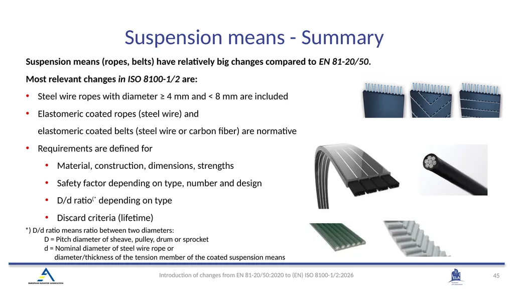
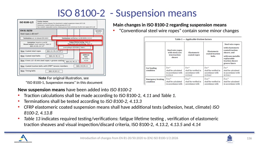
Suspension means (ropes, belts) have relatively big changes compared to EN 81-20/50.
Most relevant changes in ISO 8100-1/2 are:
Steel wire ropes with diameter ≥ 4 mm and < 8 mm are included
Elastomeric coated ropes (steel wire) and elastomeric coated belts (steel wire or carbon fiber) are normative
Requirements are defined for
Material, construction, dimensions, strengths
Safety factor depending on type, number and design
D/d ratio(* depending on type
Discard criteria (lifetime)
Traction *) D/d ratio means ratio between two diameters:
D = Pitch diameter of sheave, pulley, drum or sprocket
d = Nominal diameter of steel wire rope or
diameter/thickness of the tension member of the coated suspension means Suspension means - Summary<br>
46
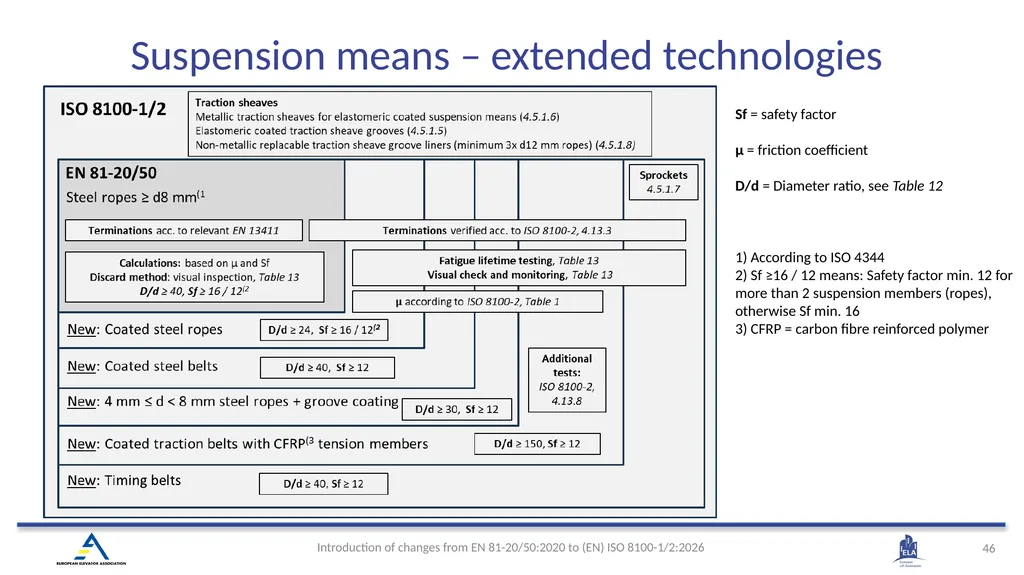
Sf = safety factor
µ = friction coefficient
D/d = Diameter ratio, see Table 12
1) According to ISO 4344
2) Sf ≥16 / 12 means: Safety factor min. 12 for more than 2 suspension members (ropes), otherwise Sf min. 16
3) CFRP = carbon fibre reinforced polymer Suspension means – extended technologies<br>
µ = friction coefficient
D/d = Diameter ratio, see Table 12
1) According to ISO 4344
2) Sf ≥16 / 12 means: Safety factor min. 12 for more than 2 suspension members (ropes), otherwise Sf min. 16
3) CFRP = carbon fibre reinforced polymer Suspension means – extended technologies<br>
47
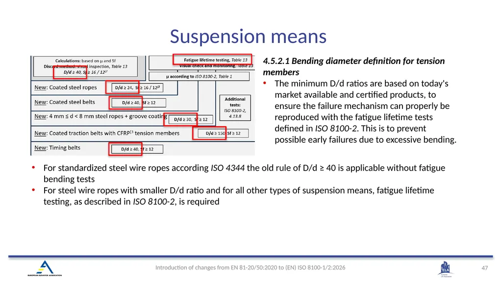
4.5.2.1 Bending diameter definition for tension members
The minimum D/d ratios are based on today's market available and certified products, to ensure the failure mechanism can properly be reproduced with the fatigue lifetime tests defined in ISO 8100-2. This is to prevent possible early failures due to excessive bending. For standardized steel wire ropes according ISO 4344 the old rule of D/d ≥ 40 is applicable without fatigue bending tests
For steel wire ropes with smaller D/d ratio and for all other types of suspension means, fatigue lifetime testing, as described in ISO 8100-2, is required Suspension means<br>
48
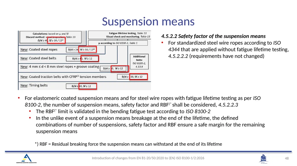
4.5.2.2 Safety factor of the suspension means
For standardized steel wire ropes according to ISO 4344 that are applied without fatigue lifetime testing, 4.5.2.2.2 (requirements have not changed) *) RBF = Residual breaking force the suspension means can withstand at the end of its lifetime For elastomeric coated suspension means and for steel wire ropes with fatigue lifetime testing as per ISO 8100-2, the number of suspension means, safety factor and RBF(* shall be considered, 4.5.2.2.3
The RBF(* limit is validated in the bending fatigue test according to ISO 8100-2
In the unlike event of a suspension means breakage at the end of the lifetime, the defined combinations of number of suspensions, safety factor and RBF ensure a safe margin for the remaining suspension means Suspension means<br>
49
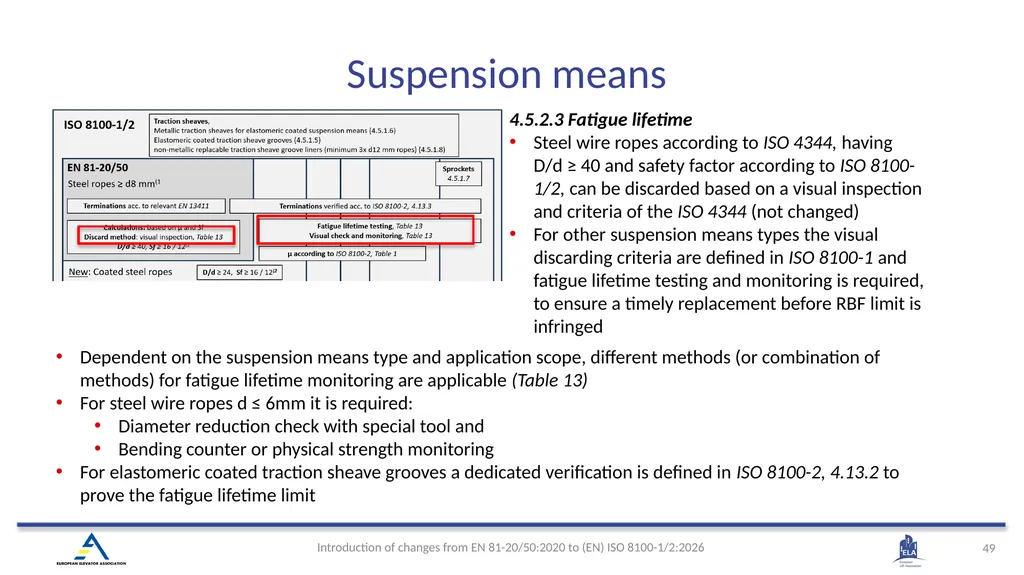
4.5.2.3 Fatigue lifetime
Steel wire ropes according to ISO 4344, having D/d ≥ 40 and safety factor according to ISO 8100-1/2, can be discarded based on a visual inspection and criteria of the ISO 4344 (not changed)
For other suspension means types the visual discarding criteria are defined in ISO 8100-1 and fatigue lifetime testing and monitoring is required, to ensure a timely replacement before RBF limit is infringed Dependent on the suspension means type and application scope, different methods (or combination of methods) for fatigue lifetime monitoring are applicable (Table 13)
For steel wire ropes d ≤ 6mm it is required:
Diameter reduction check with special tool and
Bending counter or physical strength monitoring
For elastomeric coated traction sheave grooves a dedicated verification is defined in ISO 8100-2, 4.13.2 to prove the fatigue lifetime limit Suspension means<br>
50
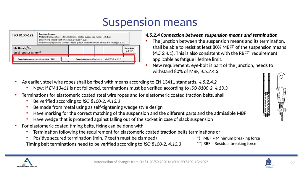
4.5.2.4 Connection between suspension means and termination
The junction between the suspension means and its termination, shall be able to resist at least 80% MBF(* of the suspension means (4.5.2.4.1). This is also consistent with the RBF(** requirement applicable as fatigue lifetime limit.
New requirement: eye-bolt is part of the junction, needs to withstand 80% of MBF, 4.5.2.4.3 *) MBF = Minimum breaking force
**) RBF = Residual breaking force Terminations for elastomeric coated steel wire ropes and for elastomeric coated traction belts, shall
Be verified according to ISO 8100-2, 4.13.3
Be made from metal using as self-tightening wedge style design
Have marking for the correct matching of the suspension and the different parts and the admissible MBF
Have wedge that is protected against falling out of the socket in case of slack suspension As earlier, steel wire ropes shall be fixed with means according to EN 13411 standards, 4.5.2.4.2
New: If EN 13411 is not followed, terminations must be verified according to ISO 8100-2, 4.13.3 For elastomeric coated timing belts, fixing can be done with
Termination following the requirement for elastomeric coated traction belts terminations or
Positive secured termination (min. 7 teeth must be clamped)
Timing belt terminations need to be verified according to ISO 8100-2, 4.13.3 Suspension means<br>
51
4.5.5 Distribution of load between the suspension means
For all new types of suspension means the same old requirements as for steel wire ropes are applicable to ensure a tension equalization
Also, the protection in the case of abnormal extension or slack suspension means is the same to all new suspension means
In that sense the elastomeric timing belt is handled like an application with chains 4.5.6 Compensation means
New suspension types can be used as compensation
Same safety factor as suspension means
Same D/d ratios as suspension means
Same monitoring as suspension means
Tensioning is required (as in EN 81-20) Suspension means<br>
52
(EN) ISO 8100-1:2026 4.6 Precautions against free fall, excessive speed, unintended car movement and creeping of the car<br>
53
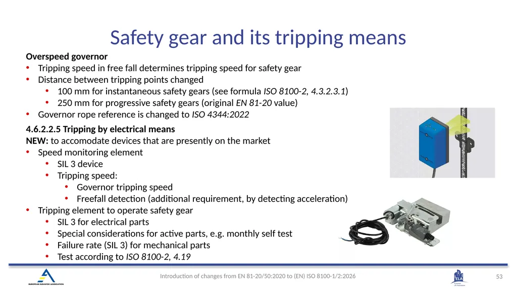
4.6.2.2.5 Tripping by electrical means
NEW: to accomodate devices that are presently on the market
Speed monitoring element
SIL 3 device
Tripping speed:
Governor tripping speed
Freefall detection (additional requirement, by detecting acceleration)
Tripping element to operate safety gear
SIL 3 for electrical parts
Special considerations for active parts, e.g. monthly self test
Failure rate (SIL 3) for mechanical parts
Test according to ISO 8100-2, 4.19 Overspeed governor
Tripping speed in free fall determines tripping speed for safety gear
Distance between tripping points changed
100 mm for instantaneous safety gears (see formula ISO 8100-2, 4.3.2.3.1)
250 mm for progressive safety gears (original EN 81-20 value)
Governor rope reference is changed to ISO 4344:2022 Safety gear and its tripping means<br>
54
ACOP (Ascending car overspeed protection) has new and changed requirements
According to EN 81-20, ACOP shall be active in
Normal operation
Manual rescue operation (with some exceptions)
ISO 8100-1: ACOP shall function in 4.6.6.1
Automatic operation
Emergency operation (except in case brake release is according to 4.9.2.3.9)
Emergency electrical operation (except if “there is a direct visual observation of the lift machine or the speed is limited by other means”)
Inspection operation
If ACOP acts on suspension or compensation means, those must be steel wire ropes (i.e. newly introduced suspension means are excluded, 4.6.6.4 c)
Better description has been added for monitoring, 4.6.6.5
An alternative speed monitoring element has been added:
Tripping by electrical means as per 4.6.2.2.5 Note: ACOP verification, see part ISO 8100-2 in this document. ACOP<br>
55
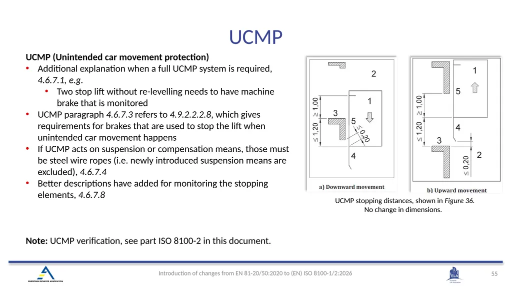
UCMP (Unintended car movement protection)
Additional explanation when a full UCMP system is required, 4.6.7.1, e.g.
Two stop lift without re-levelling needs to have machine brake that is monitored
UCMP paragraph 4.6.7.3 refers to 4.9.2.2.2.8, which gives requirements for brakes that are used to stop the lift when unintended car movement happens
If UCMP acts on suspension or compensation means, those must be steel wire ropes (i.e. newly introduced suspension means are excluded), 4.6.7.4
Better descriptions have added for monitoring the stopping elements, 4.6.7.8
Note: UCMP verification, see part ISO 8100-2 in this document. UCMP stopping distances, shown in Figure 36.
No change in dimensions. UCMP<br>
56
(EN) ISO 8100-1:2026 4.7 Guide rails<br>
57
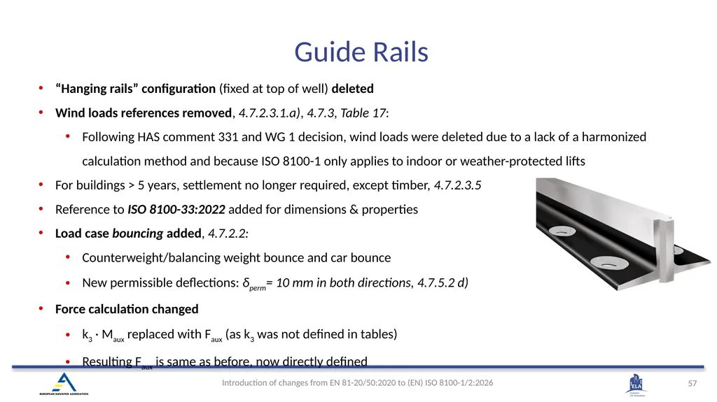
“Hanging rails” configuration (fixed at top of well) deleted
Wind loads references removed, 4.7.2.3.1.a), 4.7.3, Table 17:
Following HAS comment 331 and WG 1 decision, wind loads were deleted due to a lack of a harmonized calculation method and because ISO 8100-1 only applies to indoor or weather-protected lifts
For buildings > 5 years, settlement no longer required, except timber, 4.7.2.3.5
Reference to ISO 8100-33:2022 added for dimensions & properties
Load case bouncing added, 4.7.2.2:
Counterweight/balancing weight bounce and car bounce
New permissible deflections: δperm= 10 mm in both directions, 4.7.5.2 d)
Force calculation changed
k3 · Maux replaced with Faux (as k3 was not defined in tables)
Resulting Faux is same as before, now directly defined Guide Rails<br>
58
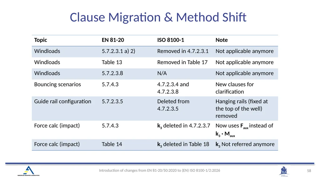
Clause Migration & Method Shift<br>
59
(EN) ISO 8100-1:2026 4.8 Buffers<br>
60
4.8 Buffers
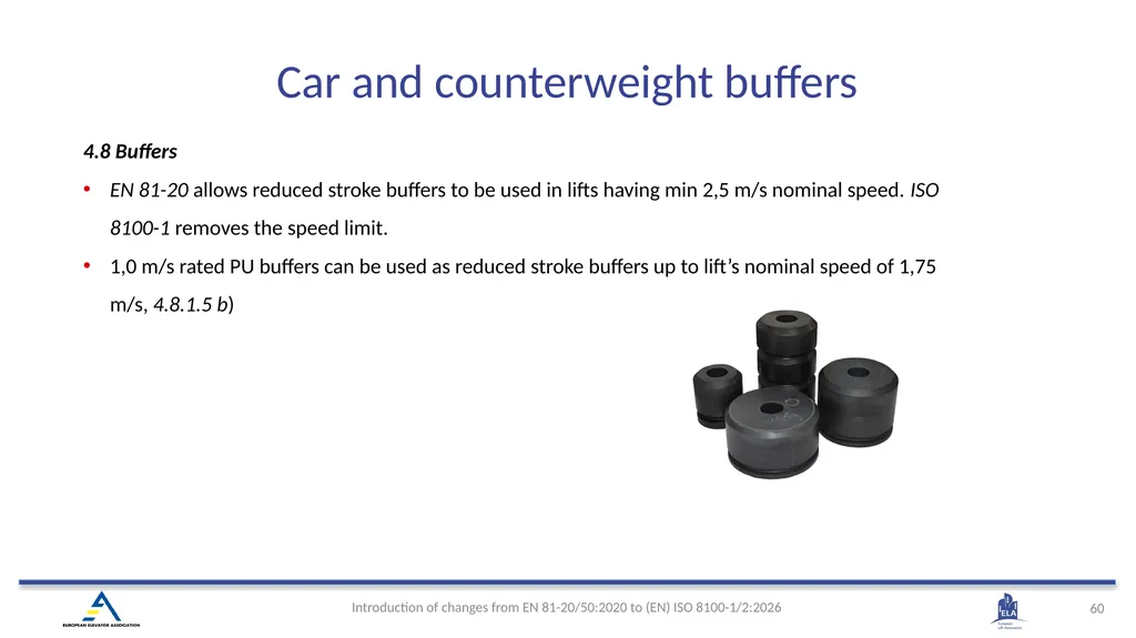
EN 81-20 allows reduced stroke buffers to be used in lifts having min 2,5 m/s nominal speed. ISO 8100-1 removes the speed limit.
1,0 m/s rated PU buffers can be used as reduced stroke buffers up to lift’s nominal speed of 1,75 m/s, 4.8.1.5 b) Car and counterweight buffers<br>
EN 81-20 allows reduced stroke buffers to be used in lifts having min 2,5 m/s nominal speed. ISO 8100-1 removes the speed limit.
1,0 m/s rated PU buffers can be used as reduced stroke buffers up to lift’s nominal speed of 1,75 m/s, 4.8.1.5 b) Car and counterweight buffers<br>
61
(EN) ISO 8100-1:2026 4.9 Lift machinery and associated equipment<br>
62
Higher brake torque requirements as minimum braking torque of the machine brake shall decelerate, stop and hold the car in case of one brake set is not working when:
The car is empty in upwards direction, and
The car is loaded with the higher of either, the rated load or the load corresponding to the overload detection setting, in downwards direction (latest at 110 %)
Manual brake release shall be independent for each brake set if machine brake is used as stopping means for ACOP or UCMP
Hydraulically actuated brakes have been added
Significant changes for interruption of the current to the brake (brake controller)
Monitoring of machine brake, either wear or brake torque, when the machine brake used to deceleration the lift: in normal operation, in ACOP, in UCMP or in case of reduced stroke buffer.
Possibility to operate each brake set independent form outside of the well
Changes at emergency operation
Static motor supply extended by SIL-rated circuits
Brake examinations and tests on installed lifts have been extended Lift machine - Summary<br>
63
General changes at machines
No speed limits for elastomeric coated ropes and belts, 4.9.2.1.1 a)
Speed for elastomeric coated timing belts is limited to 1,75 m/s, 4.9.2.1.1 b)
Transmission from motor to brake shaft can be only one belt if belts are used (previous minimum two belts if belts are used), 4.9.2.1.2
General changes at braking system
Braking part of brake system is called machine brake , 4.9.2.2.2
New wording for operation of brakes: release (change to not braking) or application (change to braking), 4.9.2.2.2.1
Extensive requirements for hydraulically released machines brakes have been added, 4.9.2.2.2.1
At minimum braking torque of the brake shall decelerate, stop and hold the car in case of one brake set is not working when:
the car is empty in upwards direction, and
The car is loaded with the higher of either, the rated load or the load corresponding to the overload detection setting, in downwards direction (latest at 110 %), 4.9.2.2.2.1
Manual release of the machine brake shall be independent for each brake set if machine brake is used as stopping means for ACOP or UCMP, 4.9.2.2.2.1
Means shall be provided to prevent lubricants from the lift machine penetrating the machine linings, 4.9.2.2.2.3 h) Lift machine<br>
64
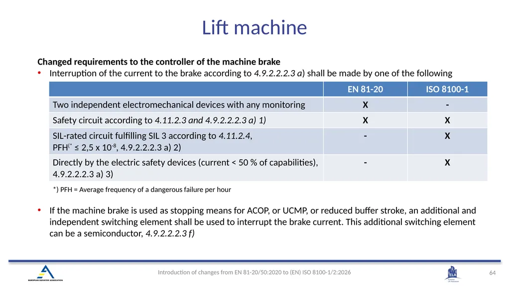
Changed requirements to the controller of the machine brake
Interruption of the current to the brake according to 4.9.2.2.2.3 a) shall be made by one of the following means:
If the machine brake is used as stopping means for ACOP, or UCMP, or reduced buffer stroke, an additional and independent switching element shall be used to interrupt the brake current. This additional switching element can be a semiconductor, 4.9.2.2.2.3 f) *) PFH = Average frequency of a dangerous failure per hour Lift machine<br>
65
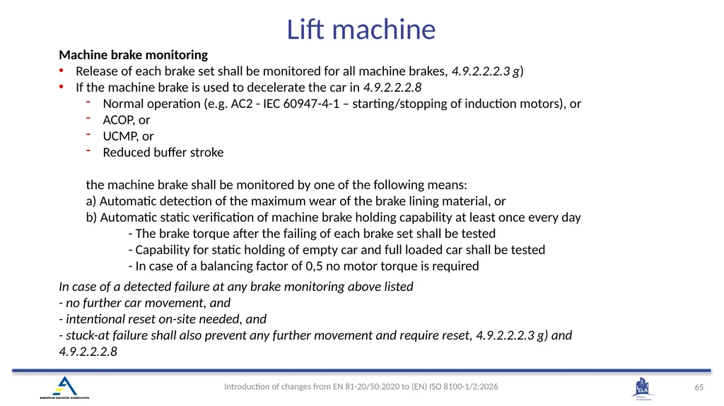
Machine brake monitoring
Release of each brake set shall be monitored for all machine brakes, 4.9.2.2.2.3 g)
If the machine brake is used to decelerate the car in 4.9.2.2.2.8
Normal operation (e.g. AC2 - IEC 60947-4-1 – starting/stopping of induction motors), or
ACOP, or
UCMP, or
Reduced buffer stroke
the machine brake shall be monitored by one of the following means: a) Automatic detection of the maximum wear of the brake lining material, or b) Automatic static verification of machine brake holding capability at least once every day
- The brake torque after the failing of each brake set shall be tested - Capability for static holding of empty car and full loaded car shall be tested - In case of a balancing factor of 0,5 no motor torque is required
In case of a detected failure at any brake monitoring above listed - no further car movement, and - intentional reset on-site needed, and - stuck-at failure shall also prevent any further movement and require reset, 4.9.2.2.2.3 g) and 4.9.2.2.2.8 Lift machine<br>
66
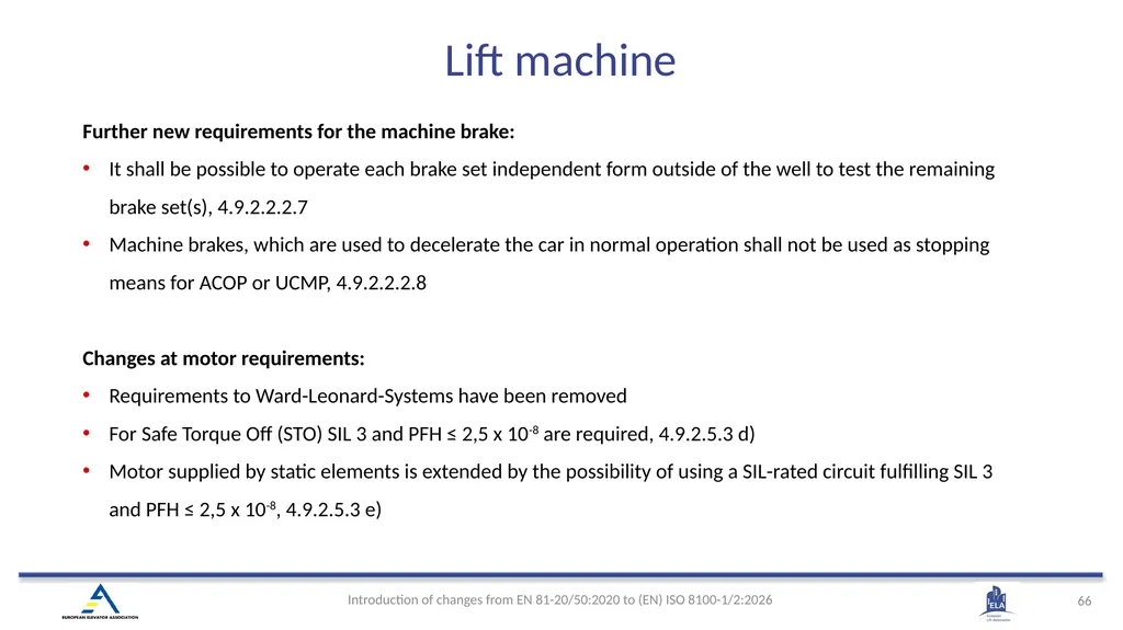
Further new requirements for the machine brake:
It shall be possible to operate each brake set independent form outside of the well to test the remaining brake set(s), 4.9.2.2.2.7
Machine brakes, which are used to decelerate the car in normal operation shall not be used as stopping means for ACOP or UCMP, 4.9.2.2.2.8
Changes at motor requirements:
Requirements to Ward-Leonard-Systems have been removed
For Safe Torque Off (STO) SIL 3 and PFH ≤ 2,5 x 10⁻⁸ are required, 4.9.2.5.3 d)
Motor supplied by static elements is extended by the possibility of using a SIL-rated circuit fulfilling SIL 3 and PFH ≤ 2,5 x 10⁻⁸, 4.9.2.5.3 e) Lift machine<br>
67
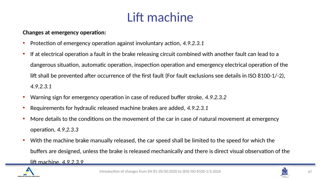
Changes at emergency operation:
Protection of emergency operation against involuntary action, 4.9.2.3.1
If at electrical operation a fault in the brake releasing circuit combined with another fault can lead to a dangerous situation, automatic operation, inspection operation and emergency electrical operation of the lift shall be prevented after occurrence of the first fault (For fault exclusions see details in ISO 8100-1/-2), 4.9.2.3.1
Warning sign for emergency operation in case of reduced buffer stroke, 4.9.2.3.2
Requirements for hydraulic released machine brakes are added, 4.9.2.3.1
More details to the conditions on the movement of the car in case of natural movement at emergency operation, 4.9.2.3.3
With the machine brake manually released, the car speed shall be limited to the speed for which the buffers are designed, unless the brake is released mechanically and there is direct visual observation of the lift machine, 4.9.2.3.9 Lift machine<br>
68
Changed references to other standards, e.g.
Request to avoid abnormal stress for fastening and mechanical damage to piping is removed. Instead, reference to ISO 4413 is added, 4.9.3.3.1.1
Deleted the reference to EN 10305 for dimensions and tolerances on tubes used for piping and jack
Updated technical information regarding hydraulic devices and their installation
Location of rupture valve and restrictor is defined more precisely
EN 81-20 defines location as “shall be accessible”. ISO 8100-1 gives clear dimension limits from the pit floor and from the car roof, 4.6.3.2 and 4.6.4.2
Jacks extending into the ground
Request for protective tube has been moved to Annex, B.2.5.3 (like many other building related conditions)
Pipes passing through wall or floor
Deleted the request to use ferrules to protect the piping Hydraulic lifts<br>
69
Changed calculations/tests/requirements of hydraulic devices
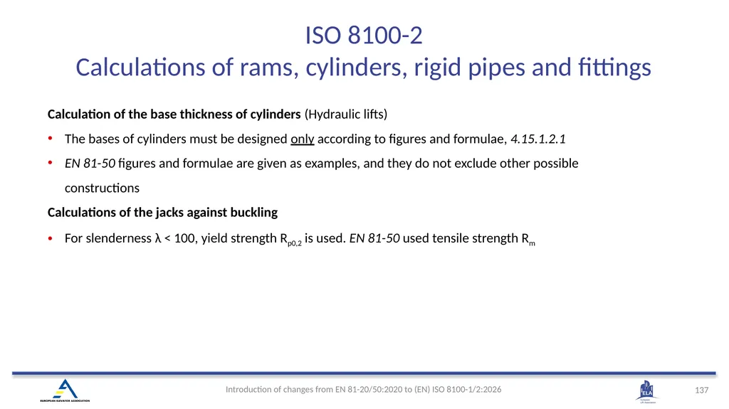
Jack buckling shall be calculated according to ISO 8100-2
Deleted permission to use “more complex calculation methods”
Pressure tests of flexible hose and couplings
The pressure test responsibility is not given to manufacturer, 4.9.3.3.3.2
Flexible hose bending radius
Deleted the requirement to fix the pipe according to manufacturer’s instructions
Relief valve setting
The maximum pressure of 50 MPa has been moved to 4.9.3.5.3.2
Motor run time limiter shall not prevent emergency electrical operation
“4.9.3.10.4 The motor run time limiter, even if tripped, shall not prevent the inspection operation, 4.12.1.5, the emergency electrical operation, 4.12.1.6, and the electrical anti-creep system, 4.12.1.10.”
For hydraulic lifts having more that two levels
Deleted the exception allowed not to check whether car is in unlocking zone, in case lift is “fitted with mechanical anti-creeping device”.
Stopping lift machine
Alternative ways to stop upwards and downwards movement has been updated, to match with other electrical and SIL requirements / possibilities in ISO 8100-1, 4.9.3.4.2 and 4.9.3.4.3 Hydraulic lifts<br>
70
(EN) ISO 8100-1:2026 4.10 Electric installations and appliances<br>
71
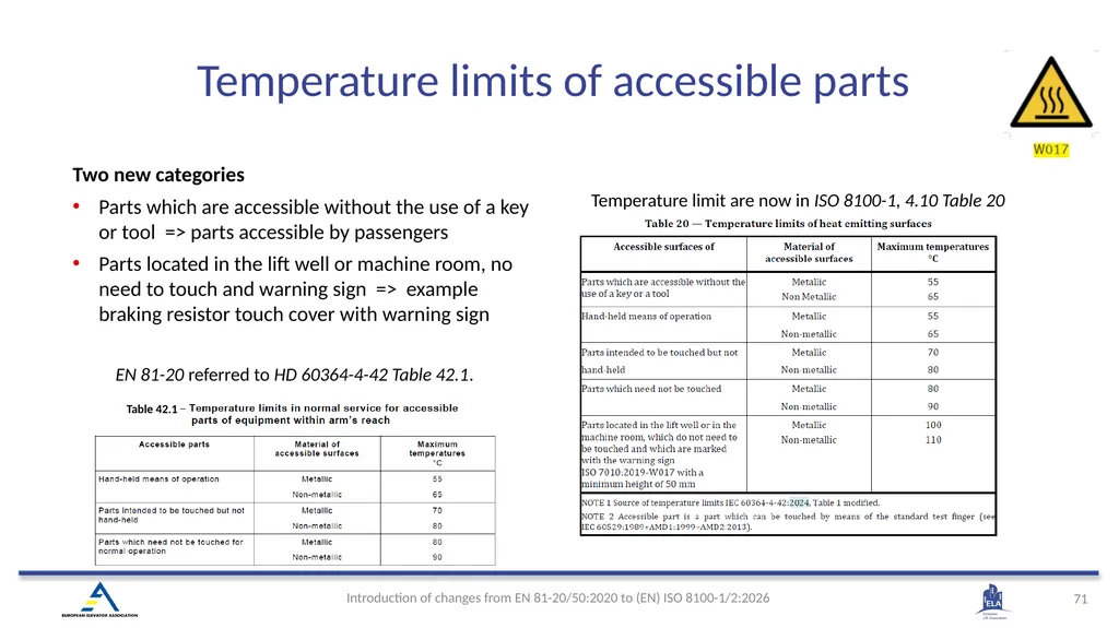
Two new categories
Parts which are accessible without the use of a key or tool => parts accessible by passengers
Parts located in the lift well or machine room, no need to touch and warning sign => example braking resistor touch cover with warning sign EN 81-20 referred to HD 60364-4-42 Table 42.1. Temperature limit are now in ISO 8100-1, 4.10 Table 20 Temperature limits of accessible parts<br>
72
To cover Machinery Regulation (MR) EHSR protection against corruption 1.1.9, interface components to external equipment shall be in accordance with ISO 8102-20:2022
“4.10.1.1.5 The lift and the lift components, capable of connectivity to external equipment:
— which is not powered by the main switch as per 4.10.5.1 or by a supply disconnecting device as per 4.10.5.3; and
— which is not located in a machine room, a pulley room, a machinery cabinet or the well as per 4.2.1.1.1;
shall be in accordance with ISO 8102-20:2022 Clause 5 and Clause 6.”
To cover new Cyber Resilience Act (CRA), ISO 8102-20 is currently been revised as EN ISO 8102-20:2027 Cybersecurity<br>
73
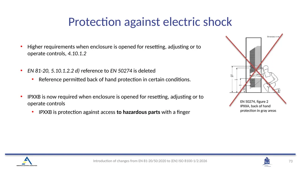
Higher requirements when enclosure is opened for resetting, adjusting or to operate controls, 4.10.1.2
EN 81-20, 5.10.1.2.2 d) reference to EN 50274 is deleted
Reference permitted back of hand protection in certain conditions.
IPXXB is now required when enclosure is opened for resetting, adjusting or to operate controls
IPXXB is protection against access to hazardous parts with a finger EN 50274, figure 2
IPXXA, back of hand protection in gray areas Protection against electric shock<br>
74
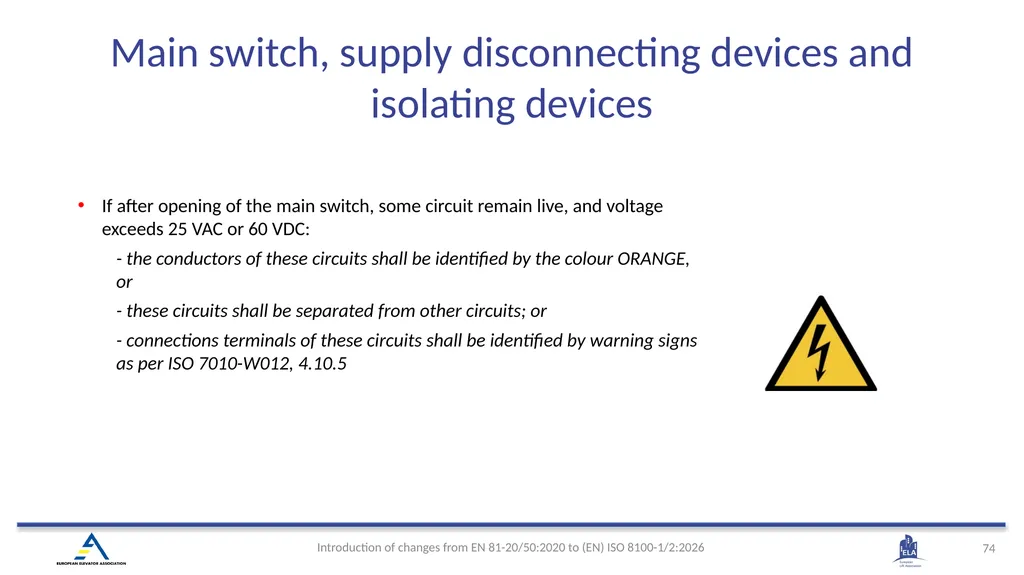
If after opening of the main switch, some circuit remain live, and voltage exceeds 25 VAC or 60 VDC:
- the conductors of these circuits shall be identified by the colour ORANGE, or
- these circuits shall be separated from other circuits; or
- connections terminals of these circuits shall be identified by warning signs as per ISO 7010-W012, 4.10.5 Main switch, supply disconnecting devices and isolating devices<br>
75
The control mechanism for the main switch shall be accessible without obstruction from the entrance(s) to the machine room.
“Directly accessible” replaced with “accessible without obstruction”
Clearer requirement also for additional isolating devices:
4.10.5.1.3 Where the main switch cannot be accessed, without moving the car from the locations of the following components:
- the control cabinet(s);
- the drive control system;
- the lift machine;
an additional device for isolating electrical equipment in accordance with IEC 60204-1:2016+A1:2021, 5.5 shall be provided at the location of that component. Main switch, supply disconnecting devices and isolating devices<br>
76
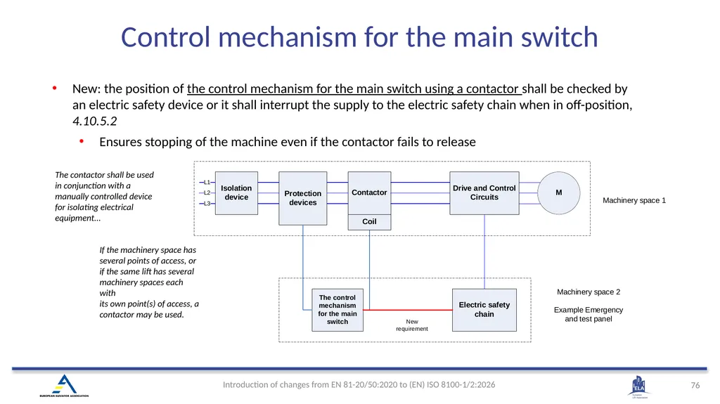
New: the position of the control mechanism for the main switch using a contactor shall be checked by an electric safety device or it shall interrupt the supply to the electric safety chain when in off-position, 4.10.5.2
Ensures stopping of the machine even if the contactor fails to release If the machinery space has several points of access, or if the same lift has several machinery spaces each with
its own point(s) of access, a contactor may be used. The contactor shall be used in conjunction with a manually controlled device for isolating electrical equipment... Control mechanism for the main switch<br>
77
New revision of EN 50214 traveling cable standard
Travelling cables shall be in accordance with EN 50214:2024 or IEC 60227-6:2001, excluding insulation and outer sheath material type requirements of those standards, 4.10.6.1.2
New: Minimum fire classification of conductors and cables
Minimum fire classification of conductors and cables installed outside enclosures shall be in accordance with EN 13501-6:2018+A1:2022 Class Eca or fire reaction shall be in accordance with minimum requirements set in IEC 60332-1-2:2004+AMD1:2015, Annex A, 4.10.6.1.3 Electric wiring<br>
78
All emergency supplies listed in 4.10.11.1
Monitoring required for all emergency supplies
The design of the emergency supply shall consider the combined power requirements of all connected devices. A monitoring system shall indicate if the capacity of the emergency supply is less than required, 4.10.11.2 Emergency supply<br>
Monitoring required for all emergency supplies
The design of the emergency supply shall consider the combined power requirements of all connected devices. A monitoring system shall indicate if the capacity of the emergency supply is less than required, 4.10.11.2 Emergency supply<br>
79
EMC standards EN 12015 and EN 12016 will be replaced with
EN ISO 8102-1:2026 emission (EMC directive)
EN ISO 8102-2:2026 immunity (EMC, LD, MD/MR directives)
Clarification that electric safety chain, safety circuits, SIL-rated circuits and “STO” as per IEC 61800-5-2 shall meet both
The “all circuits” and
The “safety circuit”
EMC immunity requirements of ISO 8102-2. Note: Current draft refers to ISO 8102-1:2020 and ISO 8102-2:2021 Electric installations and appliances Electromagnetic compatibility (EMC)<br>
80
(EN) ISO 8100-1:2026 4.11 Protection against electric faults; failure analysis; electric safety devices<br>
81
Protection against electric faults;
failure analysis New : Failure analysis shall consider short circuit between adjacent conductors of travelling cable, 4.11.1
New clarification:
Short circuit between two conductors may be excluded when the conductors are insulated for the highest voltage to which any of the conductors can be subjected.
This does not apply to adjacent conductors of traveling cable.<br>
New clarification:
Short circuit between two conductors may be excluded when the conductors are insulated for the highest voltage to which any of the conductors can be subjected.
This does not apply to adjacent conductors of traveling cable.<br>
82
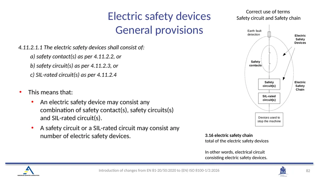
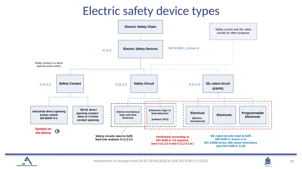
4.11.2.1.1 The electric safety devices shall consist of:
a) safety contact(s) as per 4.11.2.2, or
b) safety circuit(s) as per 4.11.2.3, or
c) SIL-rated circuit(s) as per 4.11.2.4 This means that:
An electric safety device may consist any combination of safety contact(s), safety circuits(s) and SIL-rated circuit(s).
A safety circuit or a SIL-rated circuit may consist any number of electric safety devices. 3.16 electric safety chain
total of the electric safety devices
In other words, electrical circuit consisting electric safety devices. Correct use of terms
Safety circuit and Safety chain Electric safety devices General provisions<br>
83
Explanation of terminology used
All electric safety devices have “condition for functioning”.
“Condition for functioning” shall be checked by electric safety device
When “condition” is not anymore true, electric safety device is operated, and it shall initiate stopping of the machine, unless it is bypassed.
Example of condition for functioning: 7 mm engagement of the landing door lock shall be checked by electric safety device. When engagement is less that 7 mm electric safety device is operated.
Electric safety device can be bypassed only by another electric safety device.
Equivalent terms for bypassing is “made inactive” and “muting” (used in ISO 13849-1) .
Opposite to stopping of the machine is permit running of the machine. This means that when electric safety device is not operated it permits running of the machine, but only from its own perspective. Electric safety devices General provisions<br>
84
Clarification: Electric safety device shall not be bypassed by other than:
Another electric safety device, or
Hold-to-Run control device in case inspection operation or emergency electrical operation
New: Maximum combined reaction time of the electric safety device and the equipment controlling the supply to the lift machine, to initiate stopping of the machine, shall not exceed 1 s. hold-to-run control device
control device which initiates and maintains machine functions only as long as the manual control (actuator) is actuated Electric safety devices General provisions<br>
85
If the degree of protection is less than IP4X, the electrical clearances and creepage requirements increased:
Clearance increased from 3 mm to 5,5 mm
Creepage increased from 4 mm to 8 mm
IP less than IP4X is often used example for door contacts Safety contacts<br>
Clearance increased from 3 mm to 5,5 mm
Creepage increased from 4 mm to 8 mm
IP less than IP4X is often used example for door contacts Safety contacts<br>
86
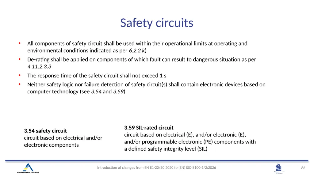
All components of safety circuit shall be used within their operational limits at operating and environmental conditions indicated as per 6.2.2 k)
De-rating shall be applied on components of which fault can result to dangerous situation as per 4.11.2.3.3
The response time of the safety circuit shall not exceed 1 s
Neither safety logic nor failure detection of safety circuit(s) shall contain electronic devices based on computer technology (see 3.54 and 3.59) 3.54 safety circuit
circuit based on electrical and/or electronic components 3.59 SIL-rated circuit
circuit based on electrical (E), and/or electronic (E), and/or programmable electronic (PE) components with
a defined safety integrity level (SIL) Safety circuits<br>
87
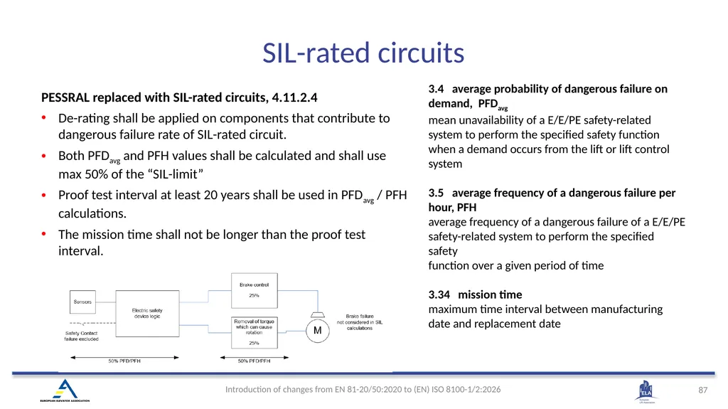
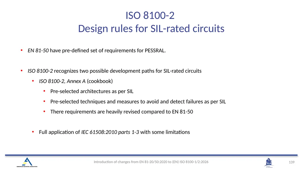
PESSRAL replaced with SIL-rated circuits, 4.11.2.4
De-rating shall be applied on components that contribute to dangerous failure rate of SIL-rated circuit.
Both PFDavg and PFH values shall be calculated and shall use max 50% of the “SIL-limit”
Proof test interval at least 20 years shall be used in PFDavg / PFH calculations.
The mission time shall not be longer than the proof test interval. 3.4 average probability of dangerous failure on demand, PFDavg
mean unavailability of a E/E/PE safety-related system to perform the specified safety function when a demand occurs from the lift or lift control system
3.5 average frequency of a dangerous failure per hour, PFH
average frequency of a dangerous failure of a E/E/PE safety-related system to perform the specified safety
function over a given period of time
3.34 mission time
maximum time interval between manufacturing date and replacement date SIL-rated circuits<br>
88
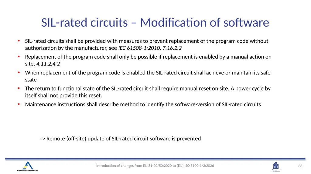
SIL-rated circuits – Modification of software SIL-rated circuits shall be provided with measures to prevent replacement of the program code without authorization by the manufacturer, see IEC 61508-1:2010, 7.16.2.2
Replacement of the program code shall only be possible if replacement is enabled by a manual action on site, 4.11.2.4.2
When replacement of the program code is enabled the SIL-rated circuit shall achieve or maintain its safe state
The return to functional state of the SIL-rated circuit shall require manual reset on site. A power cycle by itself shall not provide this reset.
Maintenance instructions shall describe method to identify the software-version of SIL-rated circuits => Remote (off-site) update of SIL-rated circuit software is prevented<br>
89
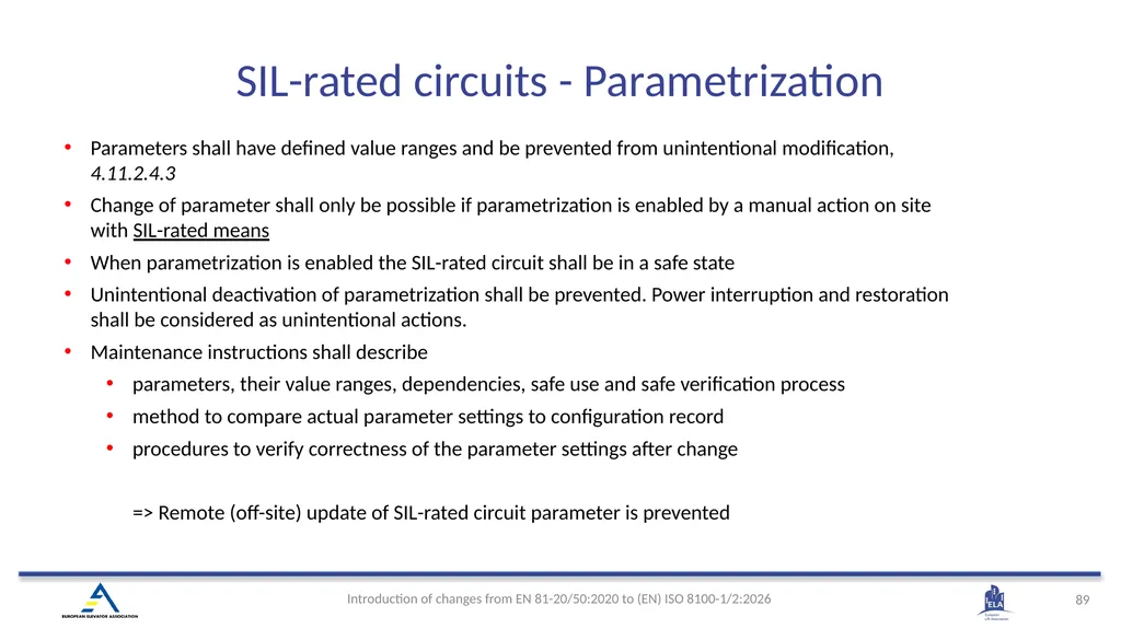
SIL-rated circuits - Parametrization Parameters shall have defined value ranges and be prevented from unintentional modification, 4.11.2.4.3
Change of parameter shall only be possible if parametrization is enabled by a manual action on site with SIL-rated means
When parametrization is enabled the SIL-rated circuit shall be in a safe state
Unintentional deactivation of parametrization shall be prevented. Power interruption and restoration shall be considered as unintentional actions.
Maintenance instructions shall describe
parameters, their value ranges, dependencies, safe use and safe verification process
method to compare actual parameter settings to configuration record
procedures to verify correctness of the parameter settings after change => Remote (off-site) update of SIL-rated circuit parameter is prevented<br>
90
Electric safety device types<br>
91
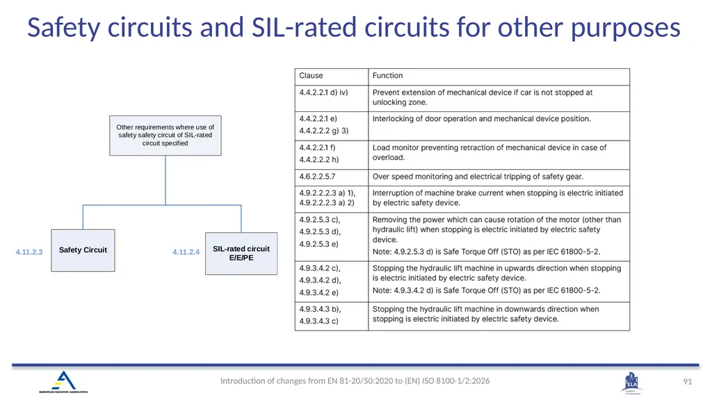
Safety circuits and SIL-rated circuits for other purposes<br>
92
(EN) ISO 8100-1:2026 4.12 Electrical Controls<br>
93
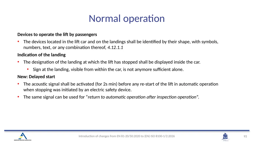
Devices to operate the lift by passengers
The devices located in the lift car and on the landings shall be identified by their shape, with symbols, numbers, text, or any combination thereof, 4.12.1.1
Indication of the landing
The designation of the landing at which the lift has stopped shall be displayed inside the car.
Sign at the landing, visible from within the car, is not anymore sufficient alone.
New: Delayed start
The acoustic signal shall be activated (for 2s min) before any re-start of the lift in automatic operation when stopping was initiated by an electric safety device.
The same signal can be used for “return to automatic operation after inspection operation”. Normal operation<br>
94
The overload shall be detected at the latest when the rated load is exceeded by 10 %, 4.12.1.2
75 kg deleted. Affects lifts having rated load less than 750 kg.
Acoustic signal sound volume is now defined
Shall be adjustable between 35 dB(A) and at least 65 dB(A)
For goods passenger lifts, it shall be adjustable up to at least 80 dB(A)
The sound level shall be measured at 1,50 m height at the centre of the door opening when the door is fully open
Optical signal defined
An optical signal in the car shall be provided, either in accordance with ISO 4190-5:2006, Table C.1 No.7 or as a word “OVERLOAD” Load control<br>
95
New: Once activated, the electric safety device shall keep the lift out of automatic operation. The return of the lift to automatic operation shall require intentional reset on site. A power cycle by itself shall not provide this reset, 4.12.1.3
New: The instructions on the release of the reduced stroke buffer, 6.2.5 Monitoring the normal slowdown of the lift machine in case of reduced stroke buffer<br>
New: The instructions on the release of the reduced stroke buffer, 6.2.5 Monitoring the normal slowdown of the lift machine in case of reduced stroke buffer<br>
96
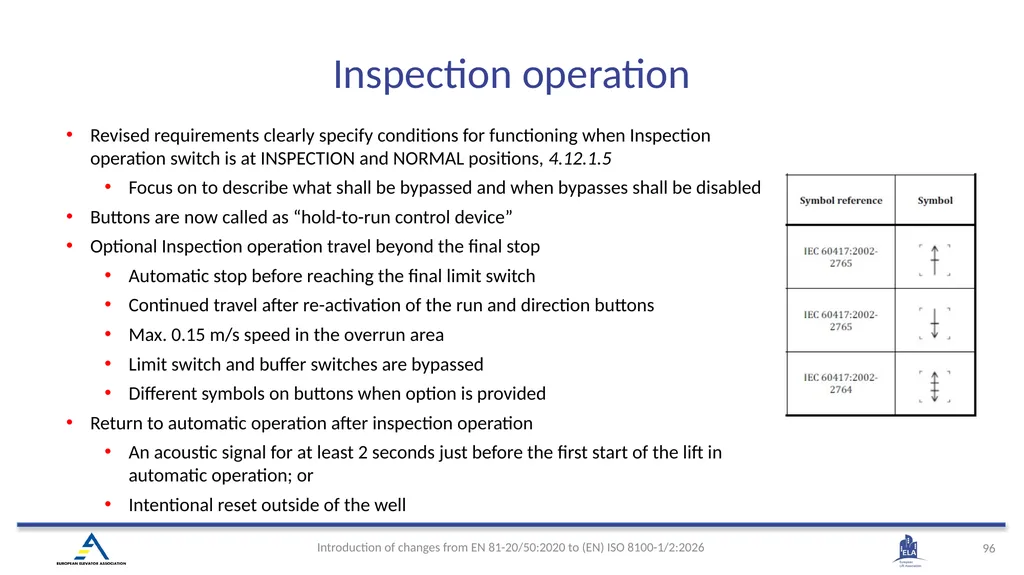
Revised requirements clearly specify conditions for functioning when Inspection operation switch is at INSPECTION and NORMAL positions, 4.12.1.5
Focus on to describe what shall be bypassed and when bypasses shall be disabled
Buttons are now called as “hold-to-run control device”
Optional Inspection operation travel beyond the final stop
Automatic stop before reaching the final limit switch
Continued travel after re-activation of the run and direction buttons
Max. 0.15 m/s speed in the overrun area
Limit switch and buffer switches are bypassed
Different symbols on buttons when option is provided
Return to automatic operation after inspection operation
An acoustic signal for at least 2 seconds just before the first start of the lift in automatic operation; or
Intentional reset outside of the well Inspection operation<br>
97
New device requirements
Emergency electrical operation (EEO) switch shall be bi-stable and shall have positions “ON” and “OFF”, 4.12.1.6
Hold-to-run control device(s) shall be used for car movement control and for bypassing the EEO-switch
Revised requirements clearly specify conditions for functioning when EEO-switch is at ON and OFF positions
Focus on to describe what shall be bypassed and when bypasses shall be disabled.
Automatic power-operated movement of the door(s) shall be prevented
Door closing and locking of the door(s) shall be controller by hold-to-run control device. This hold-to-run control device may be the same as for the car movement
Door protective device as shall be deactivated, and door(s) closing shall be with limited energy (4 J) together with acoustic signal Emergency electrical operation (EEO)<br>
98
Requirements are split in two clear groups
Conditions for functioning which shall satisfy the requirements for electric safety devices, 4.12.1.8
Bypassing the electrical safety devices of the landing doors, the landing door locks, the car door(s) and the car door locks shall be possible.
It shall not be possible to bypass both car and landing door at the same time.
Movement of the car shall only be possible in inspection operation and emergency electrical operation.
Other conditions for functioning when any of bypass device(s) is in bypass state.
Separate monitoring signal to check that the car door(s) is/are in the closed position
Acoustic signal.
Flashing light under the car is deleted. Landing and car door bypass device<br>
99
New: When entering the well, inspection operation switch is the first device to operate, not stopping device as earlier. See 4.2.1.3.1 a) for pit and 4.4.8 for car roof
New: It is not mandatory to use red push button type stopping device, 4.12.1.11
It shall be bi-stable and such that a return to service cannot result from an involuntary action Stopping devices<br>
New: It is not mandatory to use red push button type stopping device, 4.12.1.11
It shall be bi-stable and such that a return to service cannot result from an involuntary action Stopping devices<br>
100
The automatic rescue operation shall not bypass any electric safety device unless same safety function is provided by additional electric safety device, 4.12.1.12
Stopping accuracy after a car movement with automatic rescue operation shall be ±20 mm. Relevelling is not required
An acoustic signal shall operate at any time the doors are not closed, and the levelling accuracy exceeds 20 mm for more than 3 seconds 3.3 automatic rescue operation
device or function that operates automatically in case of failure or loss of power supply to move the lift car to a landing. Example of additional electric safety device:
Check on retardation in case of reduced stroke buffers can be replaced with lower constant speed limit, which is also electric safety device. Control of automatic rescue operation<br>
101
“Alarm” is renamed as “Alert”
Alert means that someone needs assistance or wants to communicate. It’s more about establishing contact rather than immediate danger.
New option to use an acoustic device (e.g. bell, siren, buzzer) instead of EN 81-28 when Lifts Directive is not applicable
a) a two-way communication system in accordance with EN 81-28:2026; or
b) an acoustic device with a sound level of 80 dB(A) at 1,00 m distance, located on the car roof or at a landing. Note: Lift Directive EHSR 4.5 ”two-way communication system for contact with a rescue service” is covered via Annex ZA of EN 81-28 Note: MD/MR EHSR 1.5.14 Risk of being trapped in a machine is covered by ISO 8100-1, 4.12.3.1 Alert initiation and intercom system<br>
102
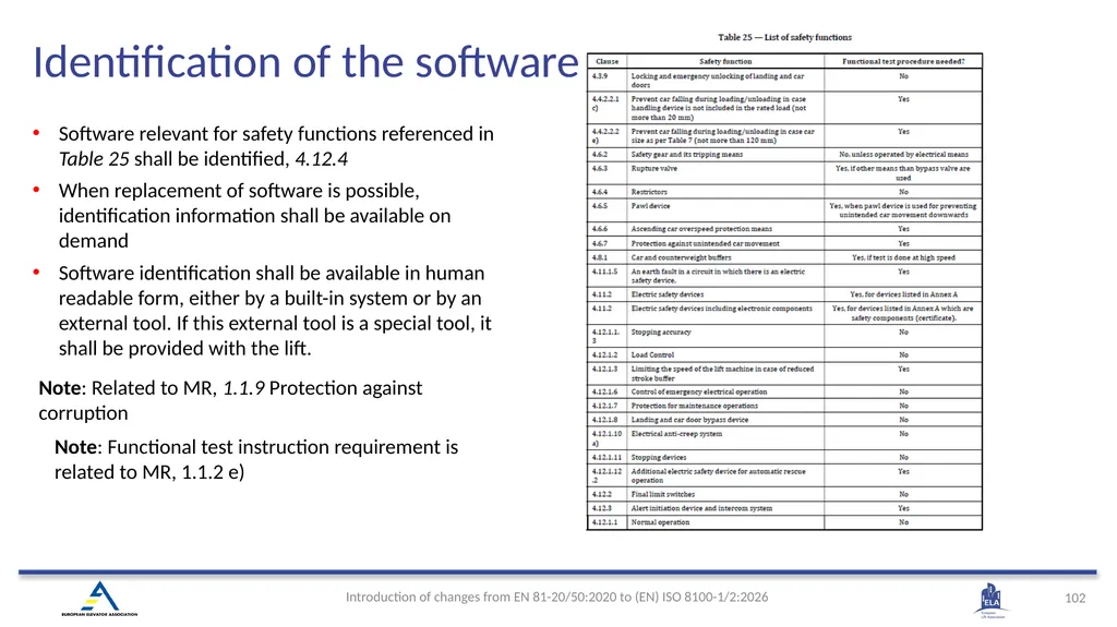
Software relevant for safety functions referenced in Table 25 shall be identified, 4.12.4
When replacement of software is possible, identification information shall be available on demand
Software identification shall be available in human readable form, either by a built-in system or by an external tool. If this external tool is a special tool, it shall be provided with the lift. Note: Related to MR, 1.1.9 Protection against corruption Note: Functional test instruction requirement is related to MR, 1.1.2 e) Identification of the software<br>
103
(EN) ISO 8100-1:2026 5 Verification of the safety requirements and/or protective measures<br>
104
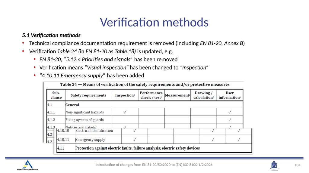
Verification methods 5.1 Verification methods
Technical compliance documentation requirement is removed (including EN 81-20, Annex B)
Verification Table 24 (in EN 81-20 as Table 18) is updated, e.g.
EN 81-20, “5.12.4 Priorities and signals” has been removed
Verification means “Visual inspection“ has been changed to “Inspection”
“4.10.11 Emergency supply” has been added<br>
105
Specific examinations and tests 5.2 Specific examinations and tests on installed lift
5.2.5 Car safety gear
There is no need to slip ropes anymore during the test, “the car is stopped by the safety gear only”
Progressive safety gears are tested
At 125 % rated load and at rated speed or
At 100 % rated load and at overspeed governor’s tripping speed
5.2.6 Counterweight or balancing weight safety gear
Tests are performed with empty car and at rated speed (lower speeds are removed)
There is no need to slip ropes anymore
5.2.8 Buffers
There is no need no check buffer compression anymore
5.2.12 ACOP
If ACOP (Ascending car overspeed protection) requires self-monitoring, it needs to be tested
5.2.14 Protection against unintended car movement (UCMP)
A check on activation means is added (if applicable)<br>
106
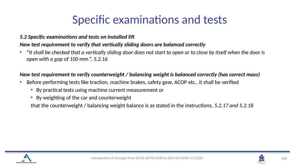
5.2 Specific examinations and tests on installed lift
New test requirement to verify that vertically sliding doors are balanced correctly
“It shall be checked that a vertically sliding door does not start to open or to close by itself when the door is open with a gap of 100 mm.”, 5.2.16
New test requirement to verify counterweight / balancing weight is balanced correctly (has correct mass)
Before performing tests like traction, machine brakes, safety gear, ACOP etc., it shall be verified
By practical tests using machine current measurement or
By weighting of the car and counterweight
that the counterweight / balancing weight balance is as stated in the instructions, 5.2.17 and 5.2.18 Specific examinations and tests <br>
107
(EN) ISO 8100-1:2026 6 Information for use<br>
108
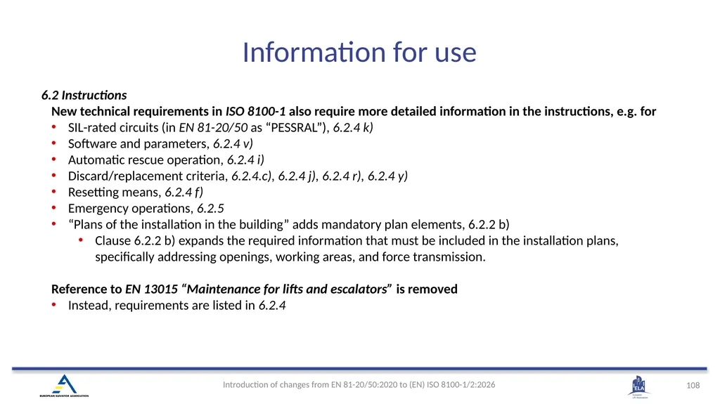
6.2 Instructions
New technical requirements in ISO 8100-1 also require more detailed information in the instructions, e.g. for
SIL-rated circuits (in EN 81-20/50 as “PESSRAL”), 6.2.4 k)
Software and parameters, 6.2.4 v)
Automatic rescue operation, 6.2.4 i)
Discard/replacement criteria, 6.2.4.c), 6.2.4 j), 6.2.4 r), 6.2.4 y)
Resetting means, 6.2.4 f)
Emergency operations, 6.2.5
“Plans of the installation in the building” adds mandatory plan elements, 6.2.2 b)
Clause 6.2.2 b) expands the required information that must be included in the installation plans, specifically addressing openings, working areas, and force transmission.
Reference to EN 13015 “Maintenance for lifts and escalators” is removed
Instead, requirements are listed in 6.2.4 Information for use<br>
109
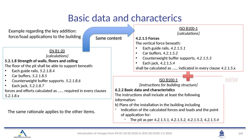
EN 81-20
[calculations]
5.2.1.8 Strength of walls, floors and ceiling
The floor of the pit shall be able to support beneath:
Each guide rails, 5.2.1.8.4
Car buffers, 5.2.1.8.5
Counterweight buffer supports. 5.2.1.8.6
Each jack, 5.2.1.8.7
forces and efforts calculated as …… required in every clauses 5.2.1.8.x ISO 8100-1
[calculations]
4.2.1.5 Forces
The vertical force beneath:
Each guide rails, 4.2.1.5.1
Car buffers, 4.2.1.5.2
Counterweight buffer supports, 4.2.1.5.3
Each jack, 4.2.1.5.4
shall be calculated as …… indicated in every clause 4.2.1.5.x ISO 8100-1
[instructions for building structure]
6.2.2 Basic data and characteristics
The instructions shall include at least the following information:
b) Plans of the installation in the building including
Indication of the calculated forces and loads and the point of application for:
The pit as per 4.2.1.5.1, 4.2.1.5.2, 4.2.1.5.3, 4.2.1.5.4 The same rationale applies to the other items. Example regarding the key addition: force/load applications to the building Same content NEW Basic data and characterics<br>
[calculations]
5.2.1.8 Strength of walls, floors and ceiling
The floor of the pit shall be able to support beneath:
Each guide rails, 5.2.1.8.4
Car buffers, 5.2.1.8.5
Counterweight buffer supports. 5.2.1.8.6
Each jack, 5.2.1.8.7
forces and efforts calculated as …… required in every clauses 5.2.1.8.x ISO 8100-1
[calculations]
4.2.1.5 Forces
The vertical force beneath:
Each guide rails, 4.2.1.5.1
Car buffers, 4.2.1.5.2
Counterweight buffer supports, 4.2.1.5.3
Each jack, 4.2.1.5.4
shall be calculated as …… indicated in every clause 4.2.1.5.x ISO 8100-1
[instructions for building structure]
6.2.2 Basic data and characteristics
The instructions shall include at least the following information:
b) Plans of the installation in the building including
Indication of the calculated forces and loads and the point of application for:
The pit as per 4.2.1.5.1, 4.2.1.5.2, 4.2.1.5.3, 4.2.1.5.4 The same rationale applies to the other items. Example regarding the key addition: force/load applications to the building Same content NEW Basic data and characterics<br>
110
6.3 Logbook needs to show only the interventions
“A logbook shall be provided for recording notes about repairs and periodic checks, including those specified in the instructions.”
Other information earlier shown in the logbook (like basic characteristis of the lift, electrical schematics diagrams) is required now to be shown in the instructions Information for use<br>
111
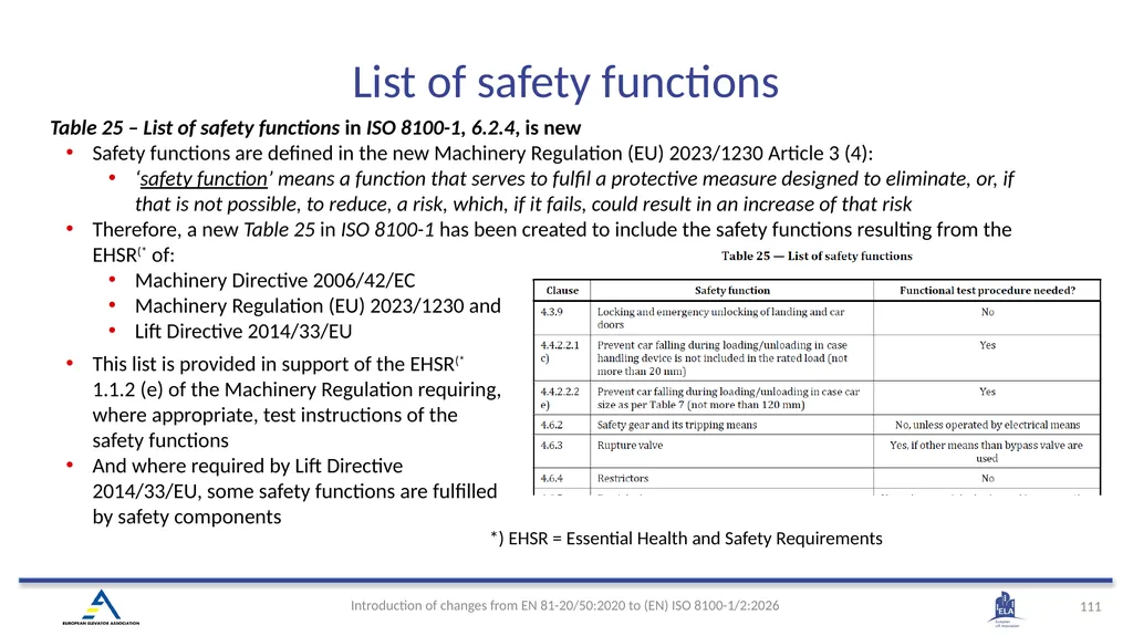
Table 25 – List of safety functions in ISO 8100-1, 6.2.4, is new
Safety functions are defined in the new Machinery Regulation (EU) 2023/1230 Article 3 (4):
‘safety function’ means a function that serves to fulfil a protective measure designed to eliminate, or, if that is not possible, to reduce, a risk, which, if it fails, could result in an increase of that risk
Therefore, a new Table 25 in ISO 8100-1 has been created to include the safety functions resulting from the EHSR(* of:
Machinery Directive 2006/42/EC
Machinery Regulation (EU) 2023/1230 and
Lift Directive 2014/33/EU *) EHSR = Essential Health and Safety Requirements This list is provided in support of the EHSR(* 1.1.2 (e) of the Machinery Regulation requiring, where appropriate, test instructions of the safety functions
And where required by Lift Directive 2014/33/EU, some safety functions are fulfilled by safety components List of safety functions<br>
112
(EN) ISO 8100-1:2026 7 Building-related boundary conditions<br>
113
New Clause 7 collects safety-relevant conditions that affect lift safety but fall outside EHSRs — thus not enforceable via harmonized standards. These are now “must-inform” obligations from the installer to the building contractor.
Example
Accessible spaces below the well
Working areas protected against environmental influences
Framing used
Keeps standard compliant
Ensures safety-critical interface is not lost due to legal separation Installer instructions for building safety<br>
Example
Accessible spaces below the well
Working areas protected against environmental influences
Framing used
Keeps standard compliant
Ensures safety-critical interface is not lost due to legal separation Installer instructions for building safety<br>
114
(EN) ISO 8100-1:2026 Annex B - Information on the building-related conditions in which the lift is installed<br>
115
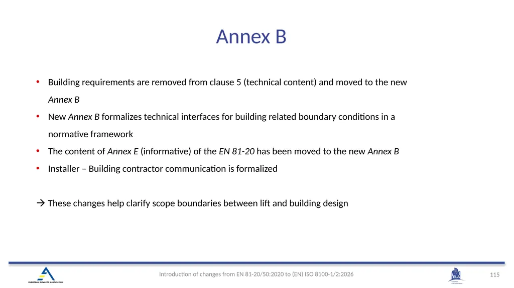
Annex B Building requirements are removed from clause 5 (technical content) and moved to the new Annex B
New Annex B formalizes technical interfaces for building related boundary conditions in a normative framework
The content of Annex E (informative) of the EN 81-20 has been moved to the new Annex B
Installer – Building contractor communication is formalized
These changes help clarify scope boundaries between lift and building design<br>
116
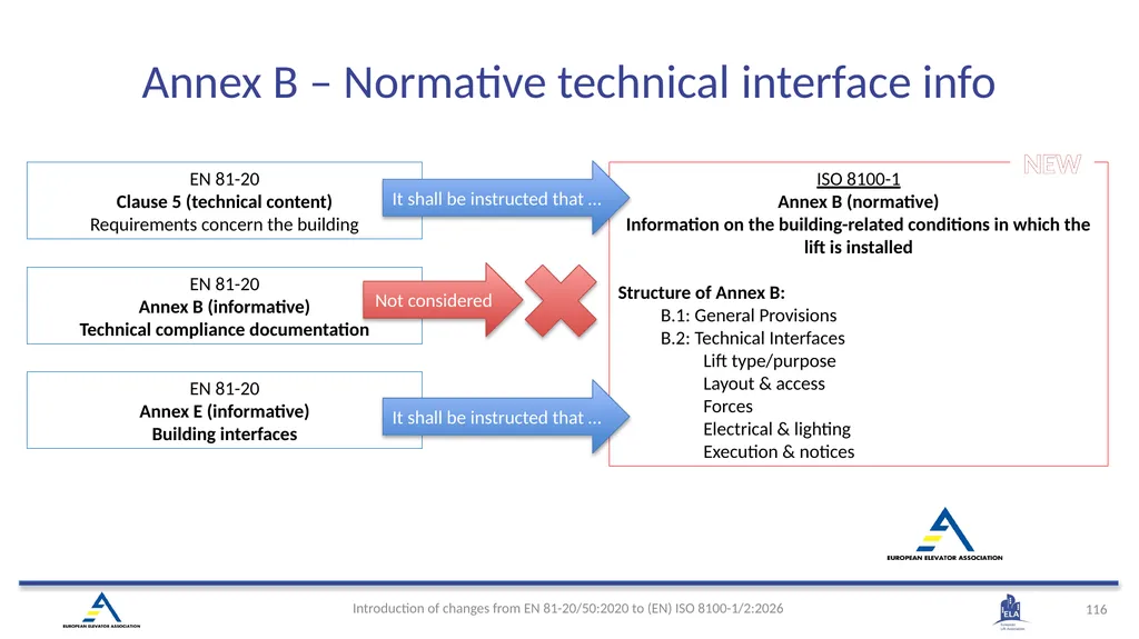
EN 81-20
Annex B (informative)
Technical compliance documentation ISO 8100-1
Annex B (normative)
Information on the building-related conditions in which the lift is installed
Structure of Annex B:
B.1: General Provisions
B.2: Technical Interfaces
Lift type/purpose
Layout & access
Forces
Electrical & lighting
Execution & notices NEW EN 81-20
Annex E (informative)
Building interfaces EN 81-20
Clause 5 (technical content)
Requirements concern the building It shall be instructed that … It shall be instructed that … Not considered Annex B – Normative technical interface info<br>
117
(EN) ISO 8100-1:2026
Annex C (normative) Pit access ladder<br>
Annex C (normative) Pit access ladder<br>
118
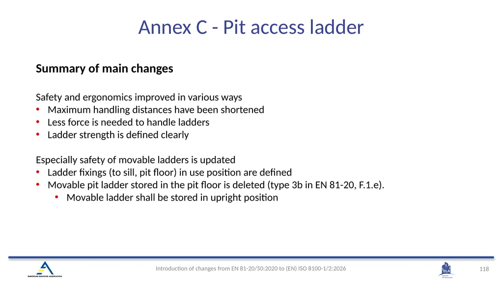
Summary of main changes
Safety and ergonomics improved in various ways
Maximum handling distances have been shortened
Less force is needed to handle ladders
Ladder strength is defined clearly
Especially safety of movable ladders is updated
Ladder fixings (to sill, pit floor) in use position are defined
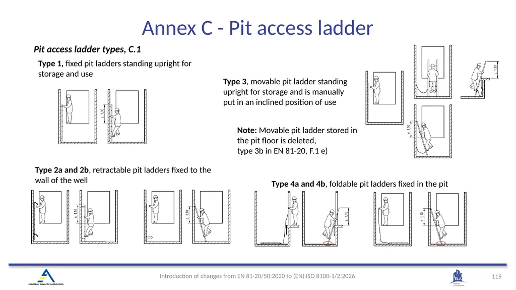
Movable pit ladder stored in the pit floor is deleted (type 3b in EN 81-20, F.1.e).
Movable ladder shall be stored in upright position Annex C - Pit access ladder<br>
119
Pit access ladder types, C.1 Type 4a and 4b, foldable pit ladders fixed in the pit Type 3, movable pit ladder standing upright for storage and is manually put in an inclined position of use Type 1, fixed pit ladders standing upright for storage and use Type 2a and 2b, retractable pit ladders fixed to the wall of the well Note: Movable pit ladder stored in the pit floor is deleted,
type 3b in EN 81-20, F.1 e) Annex C - Pit access ladder<br>
type 3b in EN 81-20, F.1 e) Annex C - Pit access ladder<br>
120
Pit access ladder strength The ladder shall be (C.2.2):
a) able to withstand a vertical force of 1 500 N;
b) able to withstand a horizontal force of 300 N; Test on stiles
Bending test load FTL shall be 700 N Test for rungs
Test load FTL shall be 2 600 N
Test load is applied to the middle of the rung Note: Test forces include safety factors Note: Test standard EN 131-2 has been replaced with ISO 14122-4 Note: 1 500 N and 300 N are requirements for complete ladder including its fixings. The mechanical strength shall be in accordance with ISO 14122-4:2016, Clause 6 (C.3.1) Annex C - Pit access ladder<br>
121
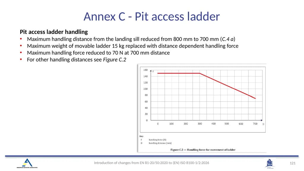
Pit access ladder handling
Maximum handling distance from the landing sill reduced from 800 mm to 700 mm (C.4 a)
Maximum weight of movable ladder 15 kg replaced with distance dependent handling force
Maximum handling force reduced to 70 N at 700 mm distance
For other handling distances see Figure C.2 Annex C - Pit access ladder<br>
122
Other changed requirements
Pit access ladders, in their stored position, shall not interfere with the refuge space, 4.2.5.8.1
If the pit access ladder is not a fixed ladder (Type 1), its stored position shall be checked by an electric safety device as per 4.11.2; see 4.2.5.8.1
In its position of use the ladder shall be fixed to the landing sill, the bottom of the pit, or the wall of the well, C.4 b)
Fixation shall prevent the ladder from tipping over when a person is standing or grasping the upper part of the ladder, C.4 c)
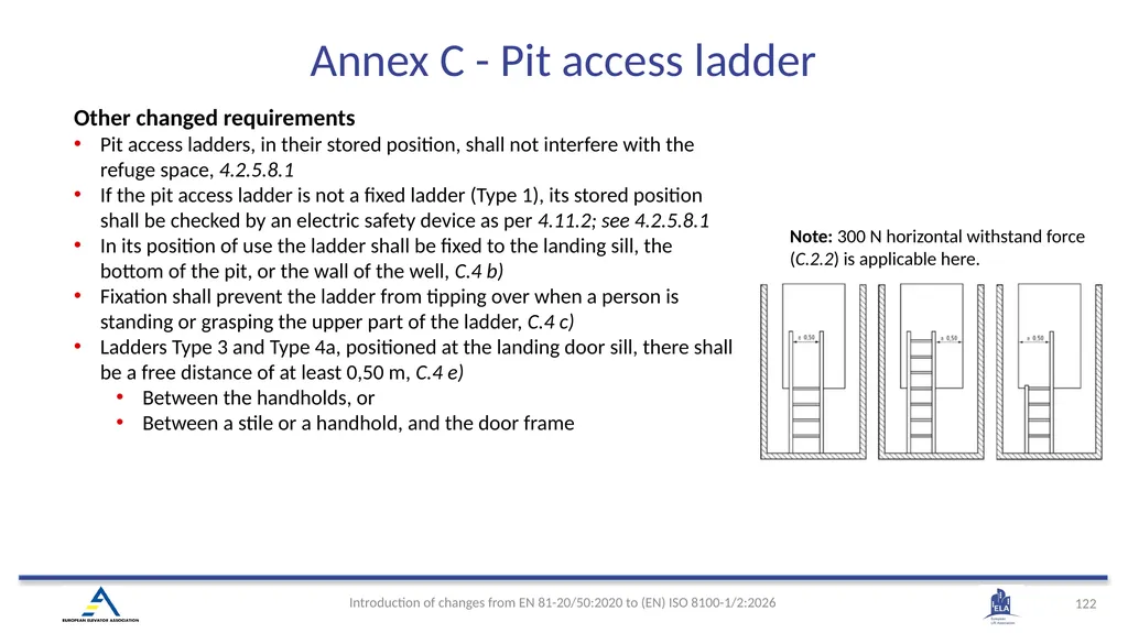
Ladders Type 3 and Type 4a, positioned at the landing door sill, there shall be a free distance of at least 0,50 m, C.4 e)
Between the handholds, or
Between a stile or a handhold, and the door frame Note: 300 N horizontal withstand force (C.2.2) is applicable here. Annex C - Pit access ladder<br>
123
Annex E
(informative)
Operation modes
overview 3.2 automatic operation
operation in which start of the movement of the car happens in response to the momentary actuation of operating devices or in response to any other automatic starting function
3.36 normal operation
automatic operation wherein the lift is used for transport of passenger or goods, and wherein the car is stopped automatically at the landings Emergency operation is used for actions where the safety chain is fully bypassed<br>
124
Annex ZA (informative)
Relationship between this European Standard and the essential requirements of
Directive 2014/33/EU aimed to be covered (EN) ISO 8100-1:2026<br>
Relationship between this European Standard and the essential requirements of
Directive 2014/33/EU aimed to be covered (EN) ISO 8100-1:2026<br>
125
Changes to Annex ZA in ISO 8100-1 and in ISO 8100-2
Applicable EHSRs(1 of Machinery Regulation(2 have been added, Table ZA.1.3
ISO 8100-1/2 clause numbers have been updated, completed and corrected to match the new numbering Note: Annex ZA is not part of the ISO final publication
Relationship between ISO 8100-1/2 and the EHSRs of Lift Directive(3 supplemented by the applicable EHSRs of Machinery Directive(4 and Machinery Regulation(2, remains as earlier
ISO 8100-1/2 provides voluntary means of conforming to the EHSRs of Lift Directive and the applicable EHSRs of Machinery Directive and Machinery Regulation as regards lifts and safety components for lifts
Once EN ISO 8100-1/2 are cited in the Official Journal of the European Union (OJEU) under 2014/33/EU, compliance with the normative clauses of this standards given in Annex ZA Tables confers, within the limits of the scope of this standard, a presumption of conformity with the corresponding EHSRs of 2014/33/EU and associated EFTA regulations.
Example: How to read Annex ZA, based on the case of EN ISO 8100-1, Annex ZA, Table ZA 1.1, 1.3 EHSR 1.3 of Lift Directive Fulfillment of these requirements and all their sub-clauses in ISO 8100-1, confers the conformity of the lift with EHSR 1.3 of Lift Directive. 1) Essential Health and Safety Requirements
2) Regulation (EU) 2023/1230
3) Directive 2014/33/EU
4) Directive 2006/42/EU Annex ZA (informative)<br>
126
(EN) ISO 8100-2:2026 4. Design rules, calculations, verifications and tests<br>
127
4.2 Verification of landing and car door locking devices
4.4 Verification of overspeed governors
4.6 Verification of safety circuits and SIL-rated circuits
4.7 Verification of ascending car overspeed protection means
4.8 Verification of unintended car movement protection means
4.10 Guide rails calculation
4.13 Verification of suspension means, compensation means and their terminations
4.15 Calculations of rams, cylinders, rigid pipes and fittings
4.17 Electrical and electronic components - Fault exclusion
4.18 Design rules for SIL-rated circuits
Annex A (normative) - SIL-rated circuits
Annex ZA (content is in ISO 8100-1 ZA)
Appendixes
Machinery Regulation impact assessment Content according to the ISO 8100-2 structure<br>
128
ISO 8100-2 content changes for testing of lift components
Reasons:
It is not possible to repeat legal obligations from for example the Lifts Directive 2014/33/EU.
The standard can only specify product requirements and how to verify the product requirements.
Examinations and/or certifications are usually done by 3rd parties. This was claimed to be misleading and therefore replaced with the wording verifications.
The instructions for safety components are not covered specifically in EN ISO 8100-1 as this is the lift standard.
ISO 8100-2 covers the EHSR for safety component instructions. Key editorial and content updates<br>
129
ISO 8100-2 structure<br>
130
ISO 8100-2 contains modified wording and changes that minimize room for interpretations, e.g.
Added “The static test and the dynamic test shall be carried out with the same test samples used in the endurance test.”, 4.2.1.2.1
During endurance test, test current needs to be double “of the locking device”, endurance test, 4.2.1.2.2
Test force “increasing progressively” is made clearer: “between 30 s to 60 s”, static test, 4.2.1.2.3
Measurable criteria has been added for mechanical tests , 4.2.1.3 ISO 8100-2 Landing doors and car doors<br>
131
Verification of overspeed governors
For the free fall test the speed shall be recorded to determine the difference between adjusted speed and the speed when an actual free fall occurs, and the safety gear needs to operate, ISO 8100-2, 4.4.2.2.1 e) ISO 8100-2 Overspeed governors<br>
For the free fall test the speed shall be recorded to determine the difference between adjusted speed and the speed when an actual free fall occurs, and the safety gear needs to operate, ISO 8100-2, 4.4.2.2.1 e) ISO 8100-2 Overspeed governors<br>
132
4.6.1.2 Information for verification clarified
E.g. Method of failure analysis employed and documented results
4.6.3.1 Mechanical test requirements clarified (vibration and shocks)
E.g. number of shocks per each axis
4.6.3.2 Temperature test requirements clarified
E.g. number of test cycles stated clearer
4.6.3.3 / 4.6.3.4 Failure analysis of safety circuit and SIL-rated circuit
New mandatory check of PFDavg and PFH calculations for SIL rated circuits
4.6.4 Instructions
Documentation requirements: must include verified technical data such as type , operation conditions, voltage and hardware/software identification ISO 8100-2 Verification of safety circuits and SIL-rated circuits<br>
133
4.7.1 General provisions has some changes, e.g.
Min. and max. masses, torques, etc. have been removed. Instead, ISO 8100-2 refers to 4.7.3 Testing
List of documents has been removed. Instead, it is referred to 4.7.4 Instructions
4.7.3.2.1 General, defines specifically
“The acceleration of the mass to reach the tripping speed shall not exceed 0,1 m/s2”. (Note: requirement Is aligned with overspeed governor test, ISO 8100-2, 4.4.2.2.2
Speed reducing element
An absolute requirement on the retardation limit of 1,0 gn is given in ISO 8100-2, 4.7.3.2.1
Clarified the number of tests required for verification of speed reducing elements (like safety gear) designed for
Single mass, ISO 8100-2, 4.7.3.2.2.2
Different masses, ISO 8100-2, 4.7.3.2.2.3
Speed monitoring element (in EN 81-50 called as “Overspeed monitoring device”)
Defined the specific number of tests to be carried out (“Twenty tests”), ISO 8100-2, 4.7.3.2.3.1
4.7.3.3 Checking after the tests
A shorter description is provided: “After the tests, a visual check shall ascertain that no deterioration, except on replaceable friction components, which affects the operation of the safety gear has occurred.” ISO 8100-2 - Verification of ascending car overspeed protection means (ACOP)<br>
134
Changes which simplify and clarify the requirements include, e.g.:
Removed key parameter limits that applicant needs to provide, like “minimum and maximum masses”, “force or torque or fluid pressure”, ISO 8100-2, 4.8.1
List of documents that shall be provided for the UCMP verification, is redefined and moved to a new clause “4.8.4 Instructions”
Testing measurement of “the average retardation” is redefined as just “the retardation”, to clarify that the measurement is made on the retardation itself and not based on a collected set of measurements, ISO 8100-2, 4.8.3.1
4.8.3.3 Checking after the tests
A shorter description is provided: “After the tests, a visual check shall ascertain that no deterioration, except on replaceable friction components, which affects the operation of the safety gear has occurred.” ISO 8100-2 - Verification of unintended car movement protection means (UCMP)<br>
135
Formulae corrected
Omega ω value was added to some buckling formulae of Annex B
Combined stress calculation completed in ISO 8100-2, Annex B (4.10.1)
Combined bending
Combined bending + compression/tension
Combined bending + buckling
Calculation methods harmonized
All methods (analytical or alternative, e.g. FEM) must use the same boundary conditions
k3 · Maux replaced with Faux (aligned with ISO 8100-1)
Annex B
Clarifies that example does not include all the load scenarios (e.g. buffer impact, bouncing scenarios) ISO 8100-2 Guide Rail Calculations<br>
136
ISO 8100-2 - Suspension means Main changes in ISO 8100-2 regarding suspension means
“Conventional steel wire ropes” contain some minor changes New suspension means have been added into ISO 8100-2
Traction calculations shall be made according to ISO 8100-2, 4.11 and Table 1.
Terminations shall be tested according to ISO 8100-2, 4.13.3
CFRP elastomeric coated suspension means shall have additional tests (adhesion, heat, climate) ISO 8100-2, 4.13.8
Table 13 indicates required testing/verifications: fatigue lifetime testing , verification of elastomeric traction sheaves and visual inspection/discard criteria, ISO 8100-2, 4.13.2, 4.13.5 and 4.14 Note For original illustration, see
“ISO 8100-1, Suspension means” in this document<br>
137
Calculation of the base thickness of cylinders (Hydraulic lifts)
The bases of cylinders must be designed only according to figures and formulae, 4.15.1.2.1
EN 81-50 figures and formulae are given as examples, and they do not exclude other possible constructions
Calculations of the jacks against buckling
For slenderness λ < 100, yield strength Rp0,2 is used. EN 81-50 used tensile strength Rm ISO 8100-2 Calculations of rams, cylinders, rigid pipes and fittings<br>
138
ISO 8100-2
Electrical and electronic components, fault exclusion Section 4.17 and Table 4 can be used exclude component faults (failure modes) in fault analysis
List of fault exclusions is not exhaustive, also other justified fault exclusion can be applied
When fault exclusion is applied to component, component shall be over-dimensioned (de-rated) by minimum factor of 1,5 on relevant parameters
Minor updates in fault exclusion criteria (Table 4)<br>
List of fault exclusions is not exhaustive, also other justified fault exclusion can be applied
When fault exclusion is applied to component, component shall be over-dimensioned (de-rated) by minimum factor of 1,5 on relevant parameters
Minor updates in fault exclusion criteria (Table 4)<br>
139
ISO 8100-2
Design rules for SIL-rated circuits EN 81-50 have pre-defined set of requirements for PESSRAL.
ISO 8100-2 recognizes two possible development paths for SIL-rated circuits
ISO 8100-2, Annex A (cookbook)
Pre-selected architectures as per SIL
Pre-selected techniques and measures to avoid and detect failures as per SIL
There requirements are heavily revised compared to EN 81-50
Full application of IEC 61508:2010 parts 1-3 with some limitations<br>
140
(EN) ISO 8100-2:2026 Annex A (normative)
SIL-rated circuits<br>
SIL-rated circuits<br>
141
ISO 8100-2
Annex A, SIL-rated circuits Comprehensive update to ISO 8100-1 Annex A, incorporating additional information to better guide development efforts
Examples of new topics
Table A.13 — Interboard safety related data communication links of SIL-rated circuits
Table A.14 — Functional safety management measures
Table A.16 — Calculation of safety-related parameters
Table A.17 — List of practices and rules of structured programming<br>
Examples of new topics
Table A.13 — Interboard safety related data communication links of SIL-rated circuits
Table A.14 — Functional safety management measures
Table A.16 — Calculation of safety-related parameters
Table A.17 — List of practices and rules of structured programming<br>
142
Designated architectures with PFD/PFH calculation formulas ISO 8100-2
Annex A (cookbook)<br>
143
List of practices and rules of structured programming
Informative references to IPA/SEC ESCR 3.0 ISO 8100-2 Annex A (cookbook)<br>
Informative references to IPA/SEC ESCR 3.0 ISO 8100-2 Annex A (cookbook)<br>
144
New and changed EHSRs in MR affecting ISO 8100-1/2
MR 1.1.2 (e): Instructions for testing of safety functions
Table 25 listing safety functions which needs additional instructions for testing
MR 1.1.9: Identification of software to be protected against corruption
… Software relevant for safety functions referenced in Table 25 shall be identified …, 4.12.4
MR 1.1.9: Cybersecurity for protection against corruption
Reference to ISO 8102-20 in clause 4.10.1.1.5
MR 1.1.9: Capability and instructions to verify actual software revisions & parameter values
Requirements in 6.2.4 v)
MR 1.1.9 & MR 1.2.1 (f): Tracing log of safety software and parameters changes
Security related event records (audit records) related to software as per 4.12.4 shall be stored at least five years, 4.10.1.1.6 Machinery Regulation impact to ISO 8100-1/2<br>