Keith Combs, Yash gujarati, Pedro urbina ROBO 380: Mechatronics Spring 2019 Robot Quadruped Goal Gait Options Creep gait (selected) Only one leg is raised and moved forward at a time, while the other legs move backward to move the body
"Keith Combs, Yash gujarati, Pedro urbina ROBO 380:" is the property of its rightful owner. Permission is granted to
download and print the materials on this website for personal, non-commercial use only, and to display it
on your personal computer provided you do not modify the materials and that you retain all copyright
notices contained in the materials. By downloading content from our website, you accept the terms of this
agreement.
Presentation Transcript
01
Keith Combs, Yash gujarati, Pedro urbina
ROBO 380: Mechatronics
Spring 2019 Robot Quadruped<br>
02
Goal<br>
03
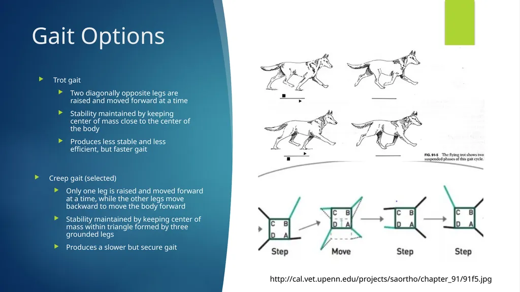
Gait Options Creep gait (selected)
Only one leg is raised and moved forward at a time, while the other legs move backward to move the body forward
Stability maintained by keeping center of mass within triangle formed by three grounded legs
Produces a slower but secure gait http://cal.vet.upenn.edu/projects/saortho/chapter_91/91f5.jpg Trot gait
Two diagonally opposite legs are raised and moved forward at a time
Stability maintained by keeping center of mass close to the center of the body
Produces less stable and less efficient, but faster gait<br>
04
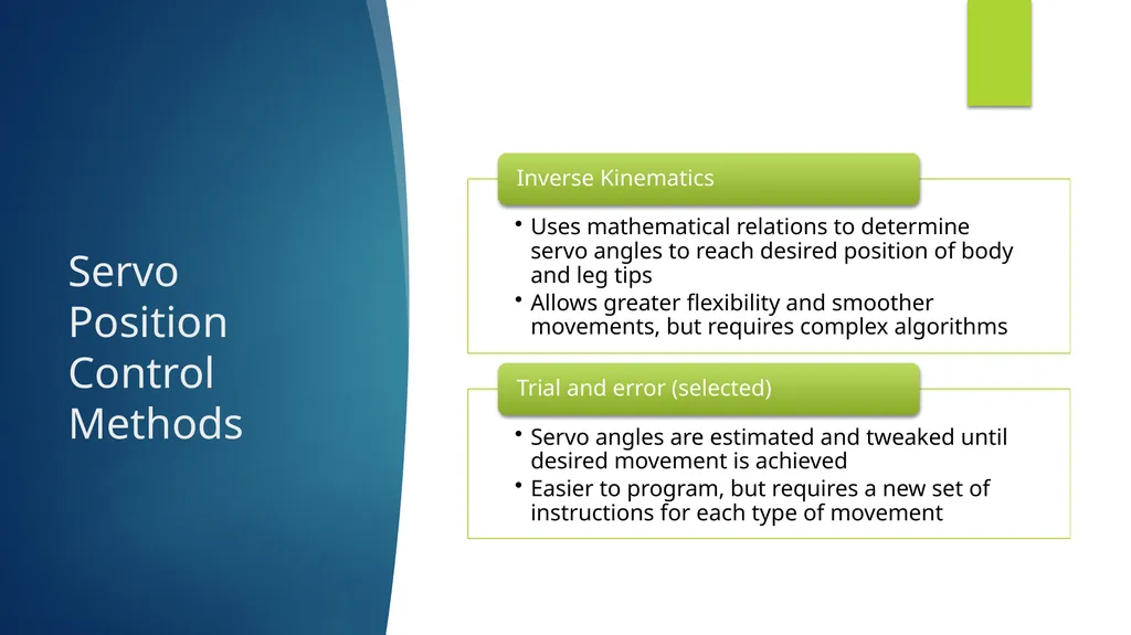
Servo Position Control Methods<br>
05
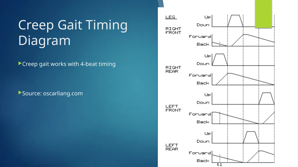
Creep Gait Timing Diagram Creep gait works with 4-beat timing
Source: oscarliang.com<br>
06
Code Overview<br>
07
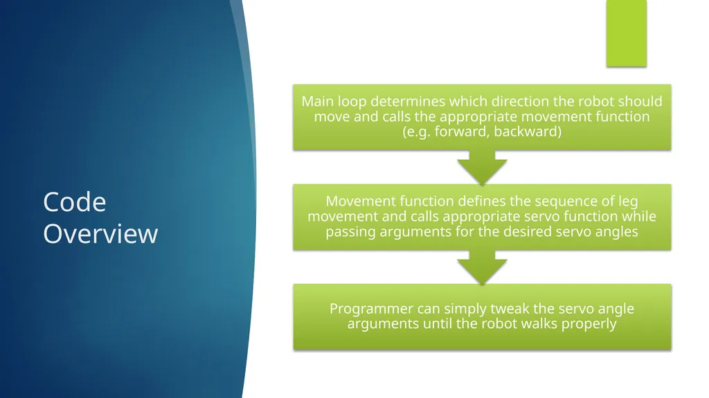
Challenges Each type of movement required a separate function to define the sequence of leg movement
Defining a new sequence and calibrating servo angles was time consuming and limited the number of movement types that could be programmed by the project deadline<br>
08
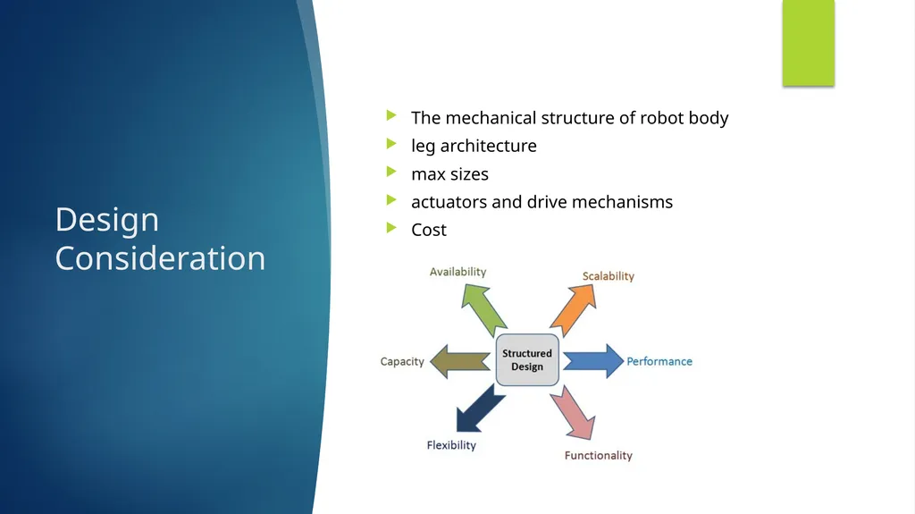
Design Consideration The mechanical structure of robot body
leg architecture
max sizes
actuators and drive mechanisms
Cost<br>
09
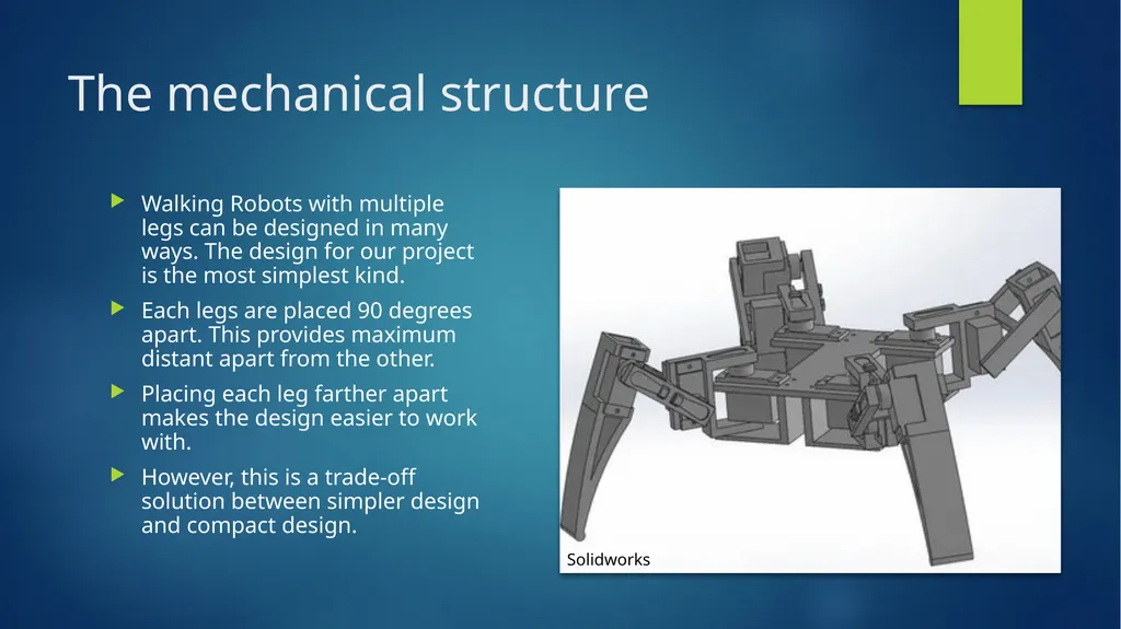
The mechanical structure Walking Robots with multiple legs can be designed in many ways. The design for our project is the most simplest kind.
Each legs are placed 90 degrees apart. This provides maximum distant apart from the other.
Placing each leg farther apart makes the design easier to work with.
However, this is a trade-off solution between simpler design and compact design. Solidworks<br>
10
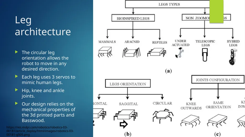
Leg architecture The circular leg orientation allows the robot to move in any desired direction.
Each leg uses 3 servos to mimic human legs.
Hip, knee and ankle joints.
Our design relies on the mechanical properties of the 3d printed parts and Basswood. https://res.mdpi.com/robotics/robotics-03-00181/article_deploy/html/images/robotics-03-00181-g005.png<br>
11
Robot body material Basswood and 3D printed parts were used for our project.
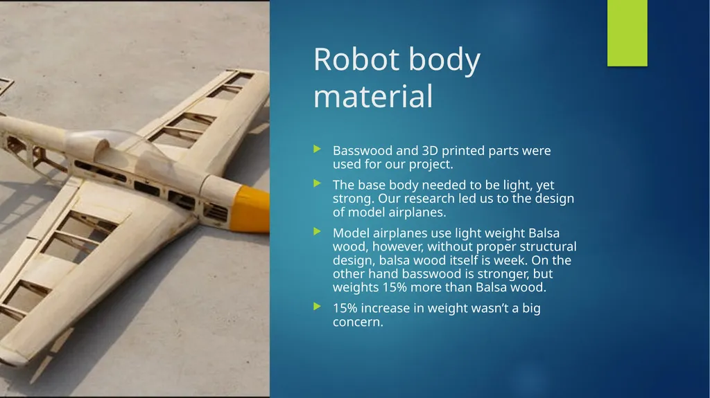
The base body needed to be light, yet strong. Our research led us to the design of model airplanes.
Model airplanes use light weight Balsa wood, however, without proper structural design, balsa wood itself is week. On the other hand basswood is stronger, but weights 15% more than Balsa wood.
15% increase in weight wasn’t a big concern.<br>
12
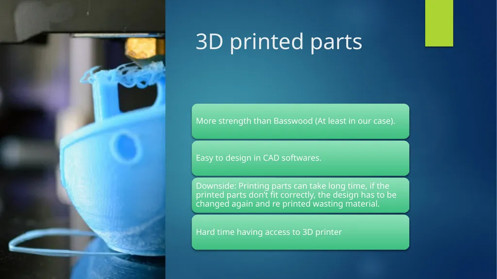
3D printed parts<br>
13
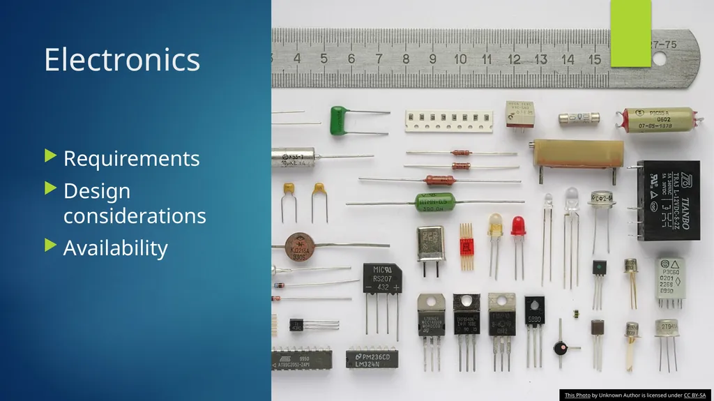
Electronics Requirements
Design considerations
Availability This Photo by Unknown Author is licensed under CC BY-SA<br>
14
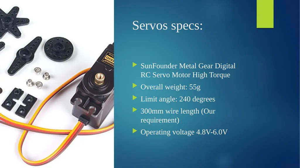
Servos specs: SunFounder Metal Gear Digital RC Servo Motor High Torque
Overall weight: 55g
Limit angle: 240 degrees
300mm wire length (Our requirement)
Operating voltage 4.8V-6.0V<br>
15
How to operate 12 servos at the same time? Driving 12+ servos with an Arduino is easy, however, this can consume our precious pins, not to mention processing power.
Our options:
Pololu Mini Maestro 12-Channel USB Servo Controller
Fully assembled 12-channel drive for a quadruped robot
This can make our life easy, very very easy. Comes preprogramed to control a quadruped using a IR sensor.
Though this would be cheating.
Our next option( eventually our choice)… This Photo by Unknown Author is licensed under CC BY-SA-NC<br>
16
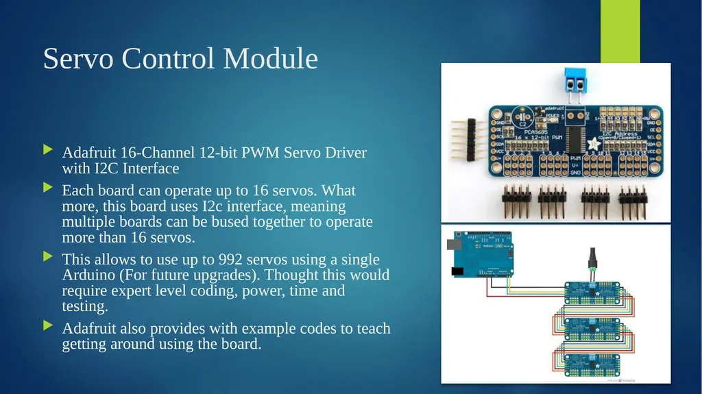
Servo Control Module Adafruit 16-Channel 12-bit PWM Servo Driver with I2C Interface
Each board can operate up to 16 servos. What more, this board uses I2c interface, meaning multiple boards can be bused together to operate more than 16 servos.
This allows to use up to 992 servos using a single Arduino (For future upgrades). Thought this would require expert level coding, power, time and testing.
Adafruit also provides with example codes to teach getting around using the board.<br>
17
Cost analysis This Photo by Unknown Author is licensed under CC BY-SA This Photo by Unknown Author is licensed under CC BY-SA-NC This Photo by Unknown Author is licensed under CC BY-NC-ND<br>
18
Final Verdict and our learning outcome To complete the project up to phase we brought it to, required us to use our knowledge and experienced not only learned in class but also from out of the class.
The project made us think and required good amount of effort
There were couple of challenges to physically create our project and to make it happen.
The major being to calculating the inverse kinematics for the robotic legs.
Our online research pointed us to PhD students work in inverse kinematics. Right at that point we realized how difficult this is going to be.
Yet we never looked back or change our project.<br>
19
This Photo by Unknown Author is licensed under CC BY-NC-ND<br>