
Presenters: Adriana Lysak, Max Buchholz, Anand
LD
Published · 69 slides · 0 views

1 / 1
Description
Presenters: Adriana Lysak, Max Buchholz, Anand Kappagantu, Angelo Hristopoulos, Weston Luke, Anthony Gregg Additional Team Members: Preston Tee, Eric Tate, Nathan Portman Advisor: Alexandra Le Moine Customer: U.S. Air Force Research
Related Topics
Share
Embed code
Download this presentation From Below
"Presenters: Adriana Lysak, Max Buchholz, Anand" is the property of its rightful owner. Permission is granted to download and print the materials on this website for personal, non-commercial use only, and to display it on your personal computer provided you do not modify the materials and that you retain all copyright notices contained in the materials. By downloading content from our website, you accept the terms of this agreement.
Presentation Transcript
01
Presenters: Adriana Lysak, Max Buchholz, Anand Kappagantu, Angelo Hristopoulos,
Weston Luke, Anthony Gregg
Additional Team Members: Preston Tee, Eric Tate, Nathan Portman
Advisor: Alexandra Le Moine
Customer: U.S. Air Force Research Laboratory FlOWeR Flow Optimization & Weight Reduction Project Preliminary Design Review FlOWeR<br>
Weston Luke, Anthony Gregg
Additional Team Members: Preston Tee, Eric Tate, Nathan Portman
Advisor: Alexandra Le Moine
Customer: U.S. Air Force Research Laboratory FlOWeR Flow Optimization & Weight Reduction Project Preliminary Design Review FlOWeR<br>
02
Project Description Baseline Design Baseline Feasibility Status and Strategy Project Description ‹#›<br>
03
Project Overview Objective:
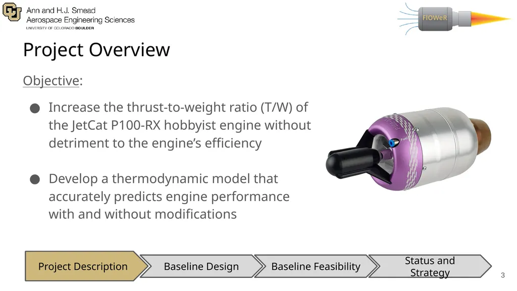
Increase the thrust-to-weight ratio (T/W) of the JetCat P100-RX hobbyist engine without detriment to the engine’s efficiency
Develop a thermodynamic model that accurately predicts engine performance with and without modifications ‹#› Baseline Design Baseline Feasibility Status and Strategy Project Description<br>
04
Motivation Performance:
Improvements may be applied to large-scale jet engines, applications to commercial, fighter aircraft
Increasing T/W = better rate of climb (RoC), maneuverability of the platform
Safety:
Thermodynamic model allows for study into engine modification with less personal, financial, and time risk ‹#› Baseline Design Baseline Feasibility Status and Strategy Project Description<br>
05
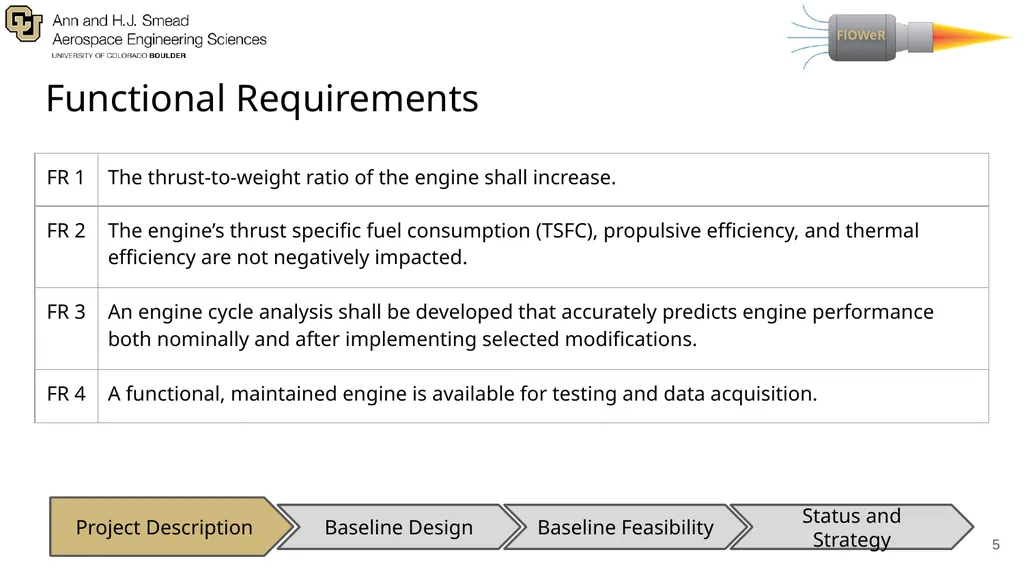
Functional Requirements ‹#› Baseline Design Baseline Feasibility Status and Strategy Project Description<br>
06
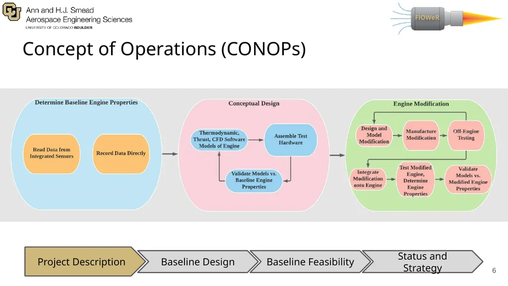
Concept of Operations (CONOPs) ‹#› Baseline Design Baseline Feasibility Status and Strategy Project Description<br>
07
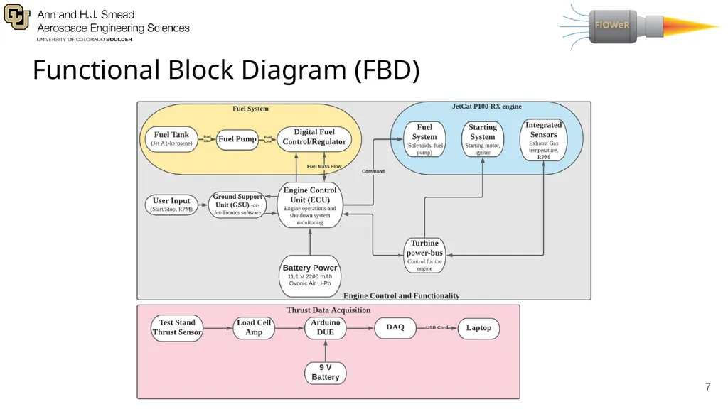
Functional Block Diagram (FBD) ‹#›<br>
08
Baseline Design Baseline Design Baseline Feasibility Status and Strategy Project Description ‹#›<br>
09
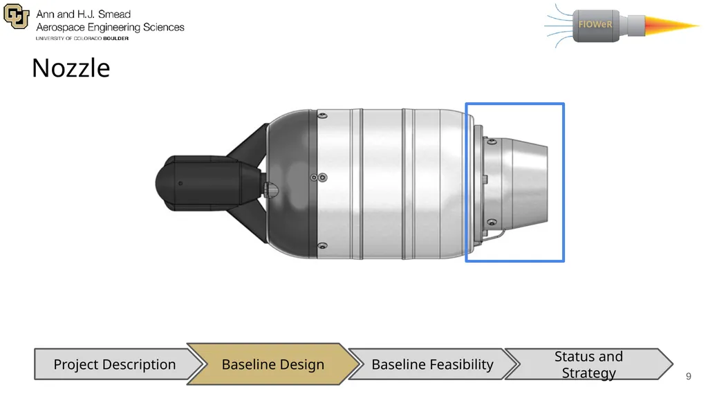
Nozzle ‹#› Baseline Design Baseline Feasibility Status and Strategy Project Description<br>
10
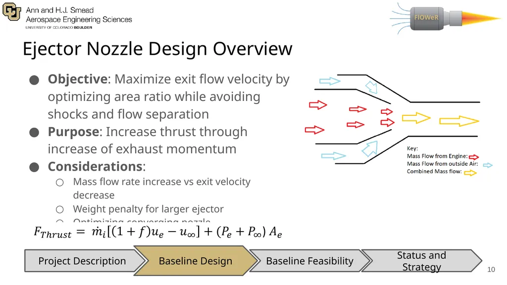
Ejector Nozzle Design Overview Objective: Maximize exit flow velocity by optimizing area ratio while avoiding shocks and flow separation
Purpose: Increase thrust through increase of exhaust momentum
Considerations:
Mass flow rate increase vs exit velocity decrease
Weight penalty for larger ejector
Optimizing converging nozzle ‹#› Baseline Design Baseline Feasibility Status and Strategy Project Description<br>
Purpose: Increase thrust through increase of exhaust momentum
Considerations:
Mass flow rate increase vs exit velocity decrease
Weight penalty for larger ejector
Optimizing converging nozzle ‹#› Baseline Design Baseline Feasibility Status and Strategy Project Description<br>
11
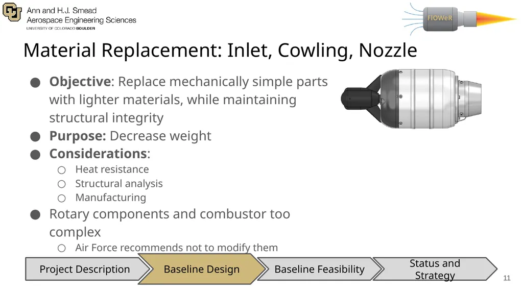
Material Replacement: Inlet, Cowling, Nozzle Objective: Replace mechanically simple parts with lighter materials, while maintaining structural integrity
Purpose: Decrease weight
Considerations:
Heat resistance
Structural analysis
Manufacturing
Rotary components and combustor too complex
Air Force recommends not to modify them ‹#› Baseline Design Baseline Feasibility Status and Strategy Project Description<br>
Purpose: Decrease weight
Considerations:
Heat resistance
Structural analysis
Manufacturing
Rotary components and combustor too complex
Air Force recommends not to modify them ‹#› Baseline Design Baseline Feasibility Status and Strategy Project Description<br>
12
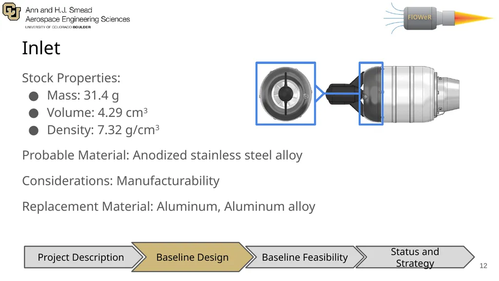
Inlet Stock Properties:
Mass: 31.4 g
Volume: 4.29 cm3
Density: 7.32 g/cm3
Probable Material: Anodized stainless steel alloy
Considerations: Manufacturability
Replacement Material: Aluminum, Aluminum alloy ‹#› Baseline Design Baseline Feasibility Status and Strategy Project Description<br>
Mass: 31.4 g
Volume: 4.29 cm3
Density: 7.32 g/cm3
Probable Material: Anodized stainless steel alloy
Considerations: Manufacturability
Replacement Material: Aluminum, Aluminum alloy ‹#› Baseline Design Baseline Feasibility Status and Strategy Project Description<br>
13
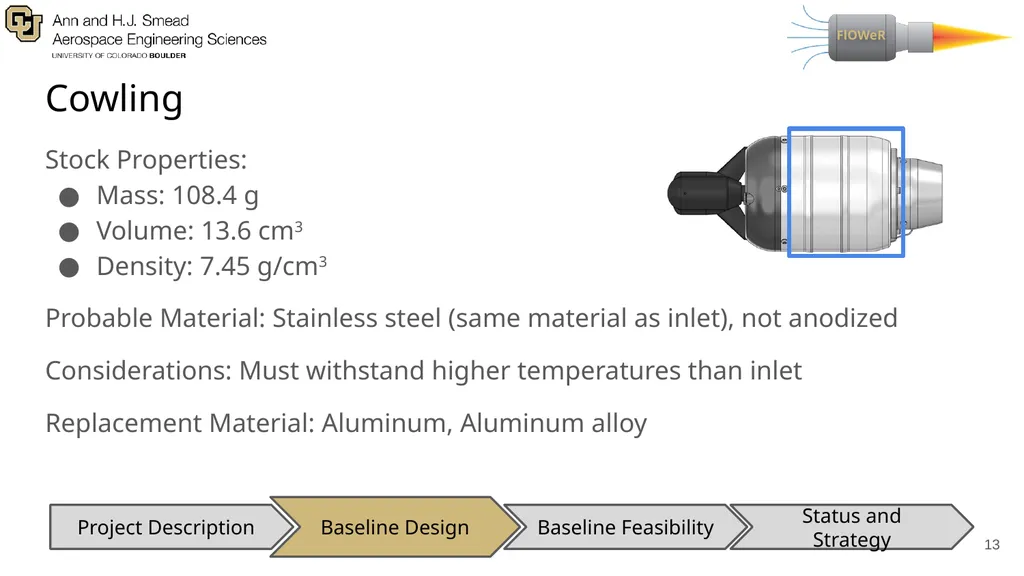
Cowling Stock Properties:
Mass: 108.4 g
Volume: 13.6 cm3
Density: 7.45 g/cm3
Probable Material: Stainless steel (same material as inlet), not anodized
Considerations: Must withstand higher temperatures than inlet
Replacement Material: Aluminum, Aluminum alloy ‹#› Baseline Design Baseline Feasibility Status and Strategy Project Description<br>
14
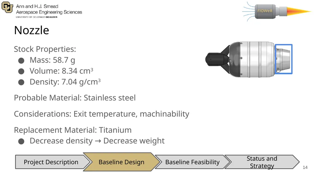
Nozzle Stock Properties:
Mass: 58.7 g
Volume: 8.34 cm3
Density: 7.04 g/cm3
Probable Material: Stainless steel
Considerations: Exit temperature, machinability
Replacement Material: Titanium
Decrease density → Decrease weight ‹#› Baseline Design Baseline Feasibility Status and Strategy Project Description<br>
Mass: 58.7 g
Volume: 8.34 cm3
Density: 7.04 g/cm3
Probable Material: Stainless steel
Considerations: Exit temperature, machinability
Replacement Material: Titanium
Decrease density → Decrease weight ‹#› Baseline Design Baseline Feasibility Status and Strategy Project Description<br>
15
Thermodynamic Model Purpose: Provide analytical reference for comparison between theoretical and experimental values of engine station properties
Inputs: Entrance and Exit Pressures and Temperatures, Exit Velocity, Compression Pressure Ratio
Outputs:Temperature and Pressure at each station
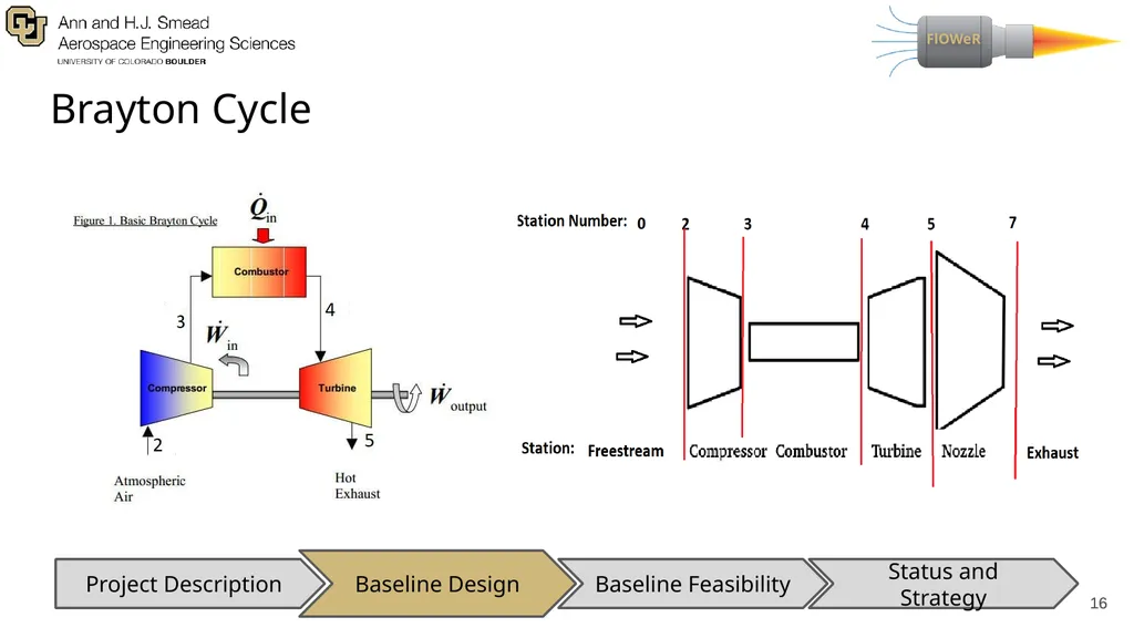
Brayton Cycle
Modeling Software
Matlab
EQL (Equilibrium Combustion of Ideal Gases) ‹#› Baseline Design Baseline Feasibility Status and Strategy Project Description Assumptions
Cp and 𝛾 are constant
Isentropic through nozzle, turbine, and compressor
Constant pressure through combustor
Adiabatic
Excluding combustor
100% thermal efficiency
Subsonic Engine assumption
Atmospheric properties at sea level<br>
16
‹#› Brayton Cycle ‹#› Baseline Design Baseline Feasibility Status and Strategy Project Description<br>
17
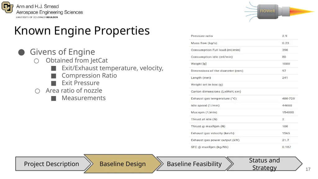
Known Engine Properties Givens of Engine
Obtained from JetCat
Exit/Exhaust temperature, velocity,
Compression Ratio
Exit Pressure
Area ratio of nozzle
Measurements ‹#› Baseline Design Baseline Feasibility Status and Strategy Project Description<br>
Obtained from JetCat
Exit/Exhaust temperature, velocity,
Compression Ratio
Exit Pressure
Area ratio of nozzle
Measurements ‹#› Baseline Design Baseline Feasibility Status and Strategy Project Description<br>
18
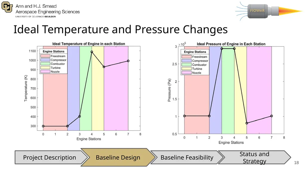
Ideal Temperature and Pressure Changes ‹#› Baseline Design Baseline Feasibility Status and Strategy Project Description<br>
19
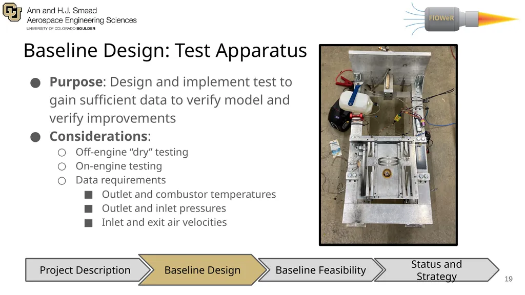
Baseline Design: Test Apparatus Purpose: Design and implement test to gain sufficient data to verify model and verify improvements
Considerations:
Off-engine “dry” testing
On-engine testing
Data requirements
Outlet and combustor temperatures
Outlet and inlet pressures
Inlet and exit air velocities ‹#› Baseline Design Baseline Feasibility Status and Strategy Project Description<br>
Considerations:
Off-engine “dry” testing
On-engine testing
Data requirements
Outlet and combustor temperatures
Outlet and inlet pressures
Inlet and exit air velocities ‹#› Baseline Design Baseline Feasibility Status and Strategy Project Description<br>
20
Baseline Feasibility Baseline Feasibility Baseline Design Status and Strategy Project Description ‹#›<br>
21
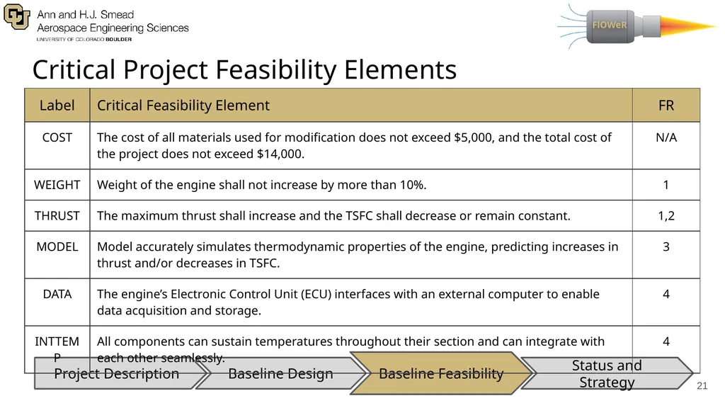
Critical Project Feasibility Elements ‹#› Baseline Feasibility Baseline Design Status and Strategy Project Description<br>
22
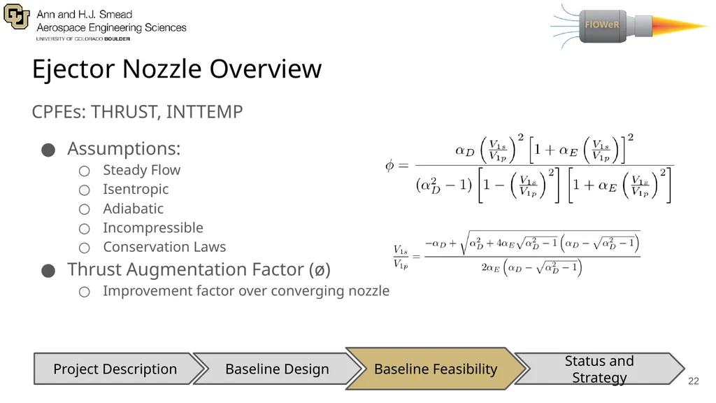
Ejector Nozzle Overview CPFEs: THRUST, INTTEMP
Assumptions:
Steady Flow
Isentropic
Adiabatic
Incompressible
Conservation Laws
Thrust Augmentation Factor (ø)
Improvement factor over converging nozzle ‹#› Baseline Feasibility Baseline Design Status and Strategy Project Description<br>
Assumptions:
Steady Flow
Isentropic
Adiabatic
Incompressible
Conservation Laws
Thrust Augmentation Factor (ø)
Improvement factor over converging nozzle ‹#› Baseline Feasibility Baseline Design Status and Strategy Project Description<br>
23
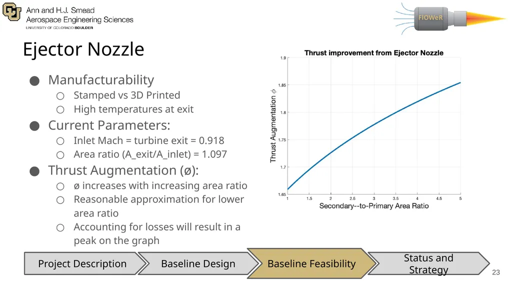
Ejector Nozzle Manufacturability
Stamped vs 3D Printed
High temperatures at exit
Current Parameters:
Inlet Mach = turbine exit = 0.918
Area ratio (A_exit/A_inlet) = 1.097
Thrust Augmentation (ø):
ø increases with increasing area ratio
Reasonable approximation for lower area ratio
Accounting for losses will result in a peak on the graph ‹#› Baseline Feasibility Baseline Design Status and Strategy Project Description<br>
24
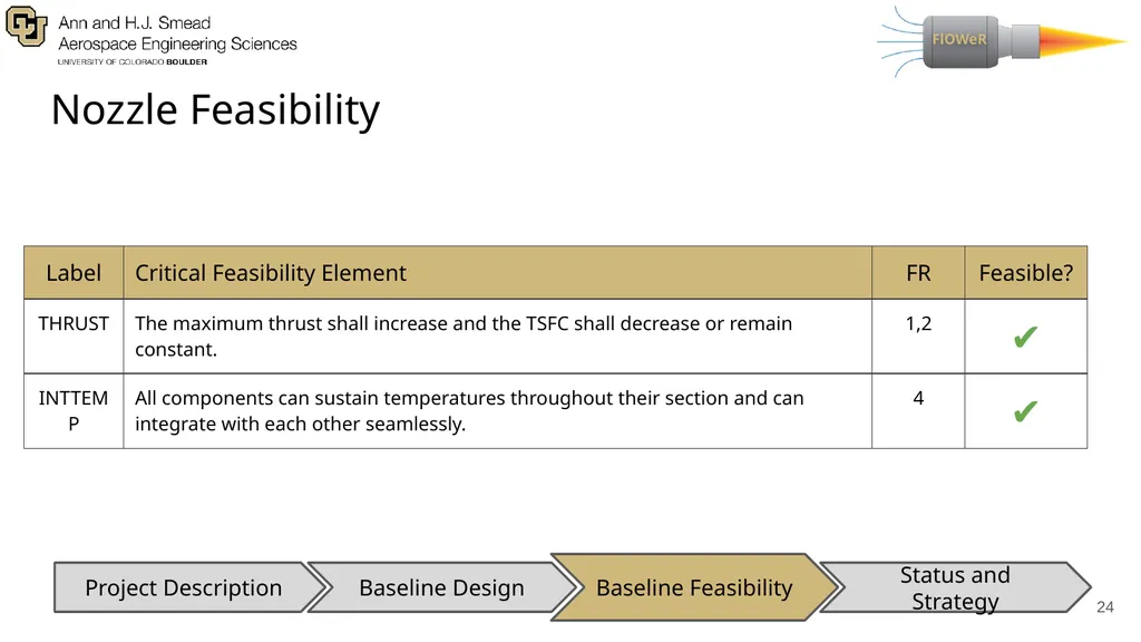
Nozzle Feasibility ‹#› Baseline Feasibility Baseline Design Status and Strategy Project Description<br>
25
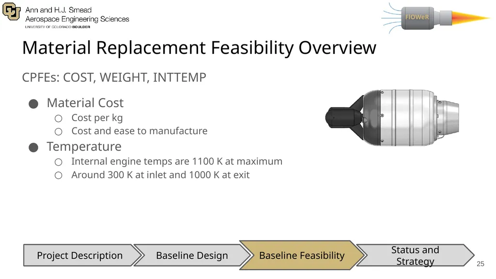
Material Replacement Feasibility Overview CPFEs: COST, WEIGHT, INTTEMP
Material Cost
Cost per kg
Cost and ease to manufacture
Temperature
Internal engine temps are 1100 K at maximum
Around 300 K at inlet and 1000 K at exit ‹#› Baseline Feasibility Baseline Design Status and Strategy Project Description<br>
Material Cost
Cost per kg
Cost and ease to manufacture
Temperature
Internal engine temps are 1100 K at maximum
Around 300 K at inlet and 1000 K at exit ‹#› Baseline Feasibility Baseline Design Status and Strategy Project Description<br>
26
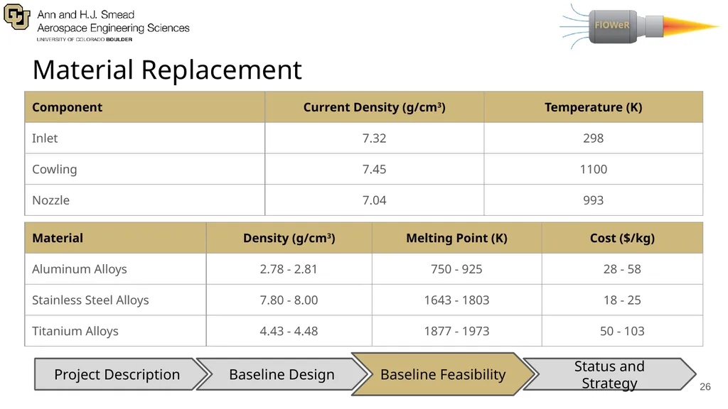
Material Replacement ‹#› Baseline Feasibility Baseline Design Status and Strategy Project Description<br>
27
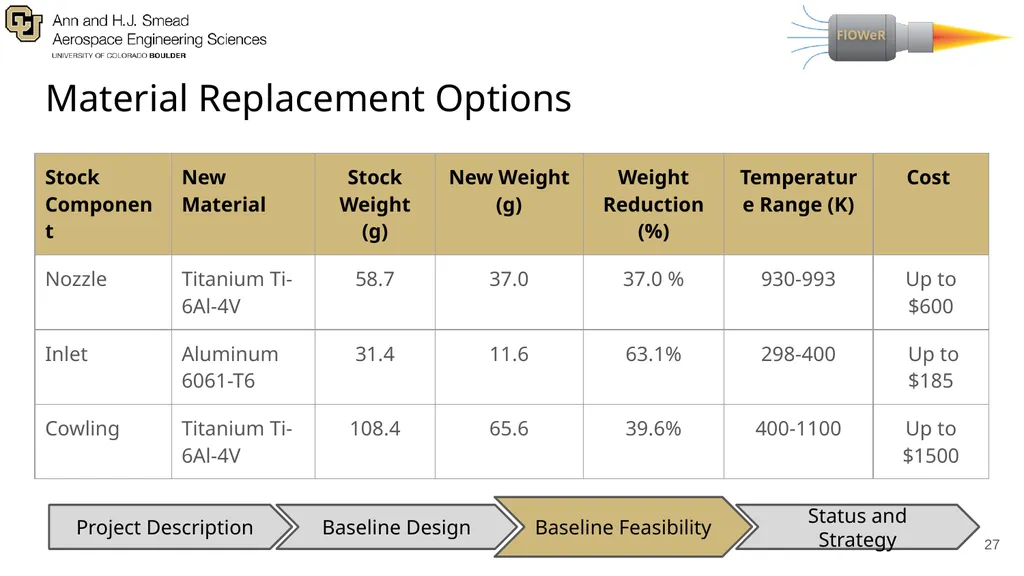
Material Replacement Options ‹#› Baseline Feasibility Baseline Design Status and Strategy Project Description<br>
28
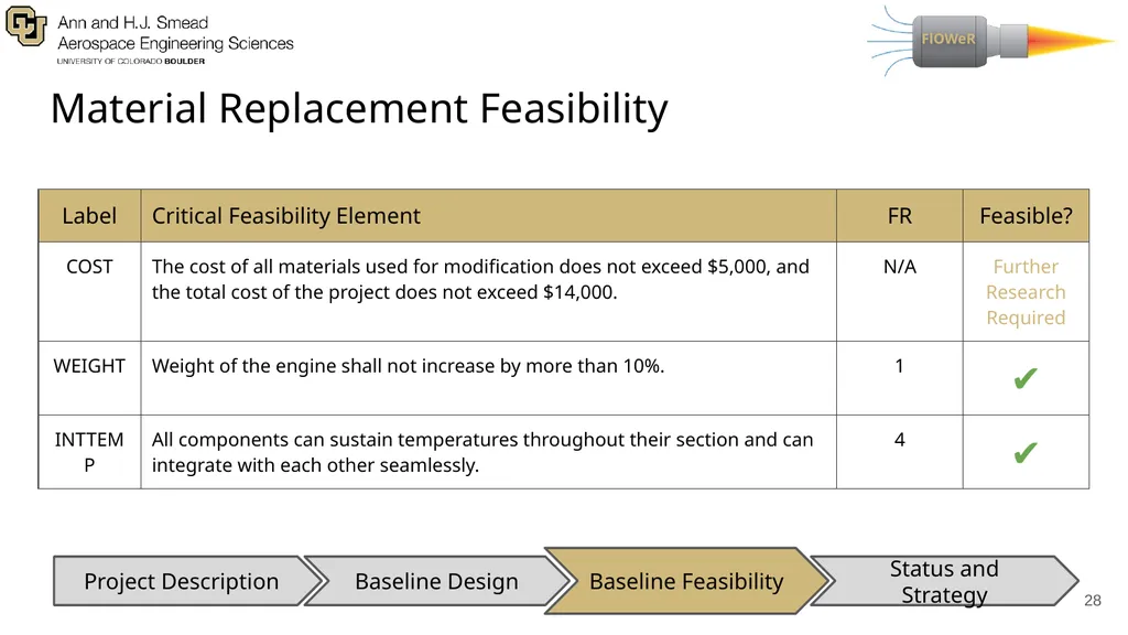
Material Replacement Feasibility ‹#› Baseline Feasibility Baseline Design Status and Strategy Project Description<br>
29
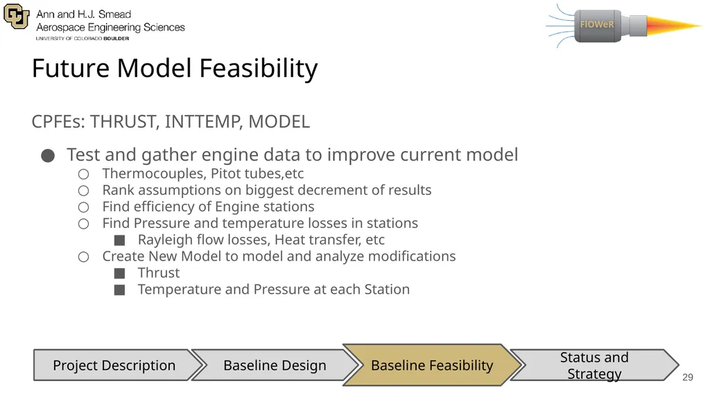
Future Model Feasibility ‹#› Baseline Feasibility Baseline Design Status and Strategy Project Description CPFEs: THRUST, INTTEMP, MODEL
Test and gather engine data to improve current model
Thermocouples, Pitot tubes,etc
Rank assumptions on biggest decrement of results
Find efficiency of Engine stations
Find Pressure and temperature losses in stations
Rayleigh flow losses, Heat transfer, etc
Create New Model to model and analyze modifications
Thrust
Temperature and Pressure at each Station<br>
30
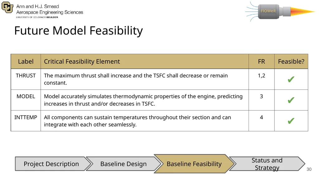
Future Model Feasibility ‹#› Baseline Feasibility Baseline Design Status and Strategy Project Description<br>
31
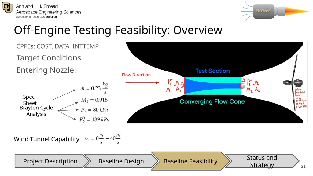
Off-Engine Testing Feasibility: Overview CPFEs: COST, DATA, INTTEMP
Target Conditions
Entering Nozzle: ‹#› Baseline Feasibility Baseline Design Status and Strategy Project Description Spec Sheet Brayton Cycle
Analysis Flow Direction Wind Tunnel Capability:<br>
Target Conditions
Entering Nozzle: ‹#› Baseline Feasibility Baseline Design Status and Strategy Project Description Spec Sheet Brayton Cycle
Analysis Flow Direction Wind Tunnel Capability:<br>
32
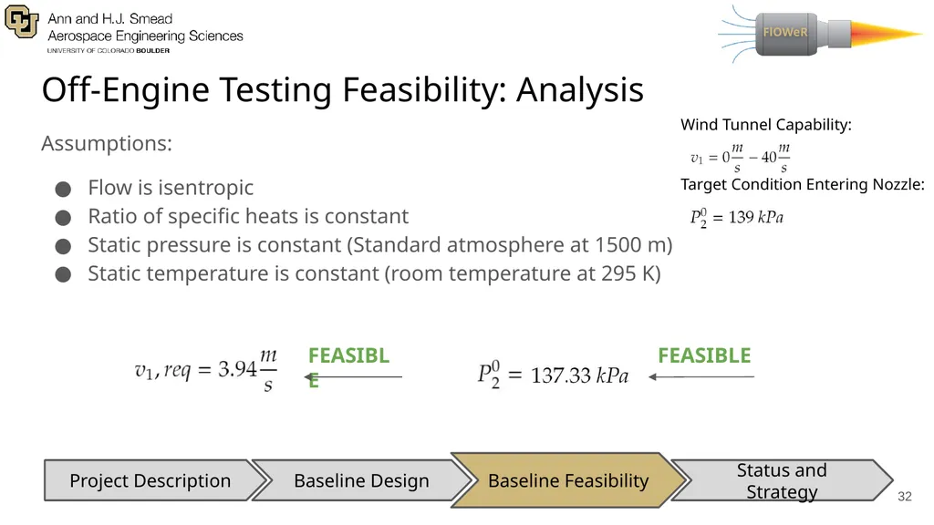
Off-Engine Testing Feasibility: Analysis Assumptions:
Flow is isentropic
Ratio of specific heats is constant
Static pressure is constant (Standard atmosphere at 1500 m)
Static temperature is constant (room temperature at 295 K) ‹#› Baseline Feasibility Baseline Design Status and Strategy Project Description FEASIBLE Wind Tunnel Capability: Target Condition Entering Nozzle: FEASIBLE<br>
33
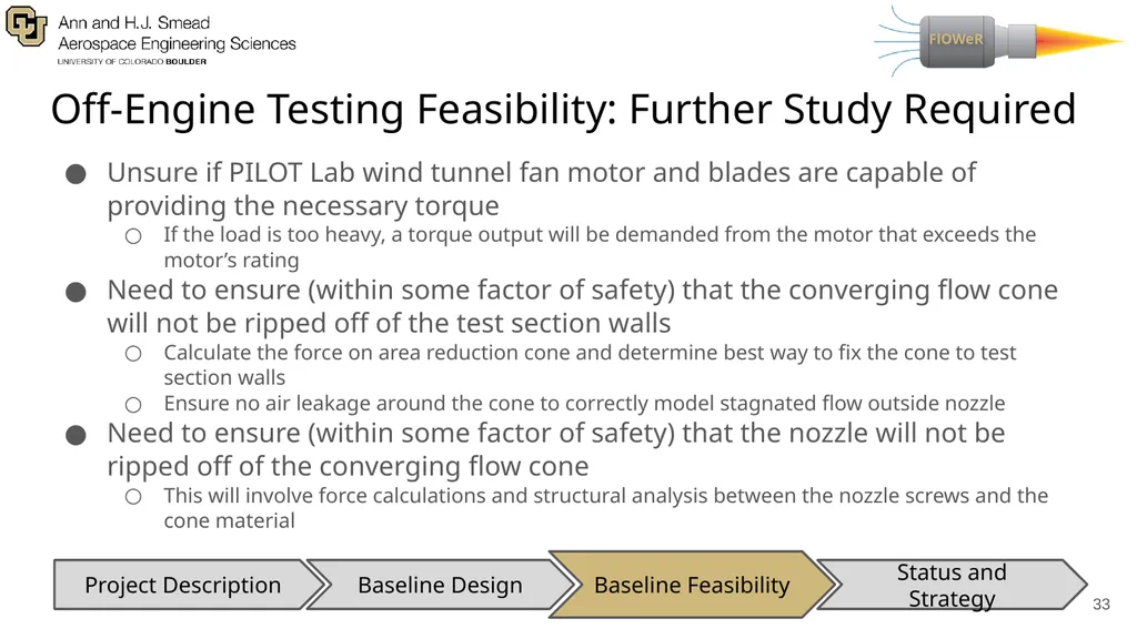
Off-Engine Testing Feasibility: Further Study Required Unsure if PILOT Lab wind tunnel fan motor and blades are capable of providing the necessary torque
If the load is too heavy, a torque output will be demanded from the motor that exceeds the motor’s rating
Need to ensure (within some factor of safety) that the converging flow cone will not be ripped off of the test section walls
Calculate the force on area reduction cone and determine best way to fix the cone to test section walls
Ensure no air leakage around the cone to correctly model stagnated flow outside nozzle
Need to ensure (within some factor of safety) that the nozzle will not be ripped off of the converging flow cone
This will involve force calculations and structural analysis between the nozzle screws and the cone material ‹#› Baseline Feasibility Baseline Design Status and Strategy Project Description<br>
34
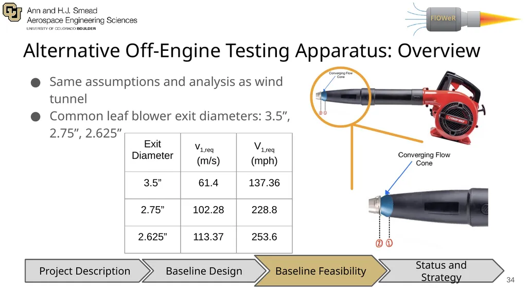
Alternative Off-Engine Testing Apparatus: Overview Same assumptions and analysis as wind tunnel
Common leaf blower exit diameters: 3.5”, 2.75”, 2.625” ‹#› Baseline Feasibility Baseline Design Status and Strategy Project Description<br>
Common leaf blower exit diameters: 3.5”, 2.75”, 2.625” ‹#› Baseline Feasibility Baseline Design Status and Strategy Project Description<br>
35
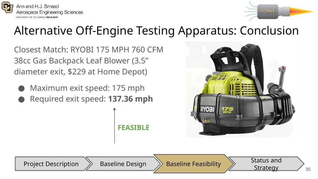
Alternative Off-Engine Testing Apparatus: Conclusion Closest Match: RYOBI 175 MPH 760 CFM 38cc Gas Backpack Leaf Blower (3.5” diameter exit, $229 at Home Depot)
Maximum exit speed: 175 mph
Required exit speed: 137.36 mph ‹#› FEASIBLE Baseline Feasibility Baseline Design Status and Strategy Project Description<br>
Maximum exit speed: 175 mph
Required exit speed: 137.36 mph ‹#› FEASIBLE Baseline Feasibility Baseline Design Status and Strategy Project Description<br>
36
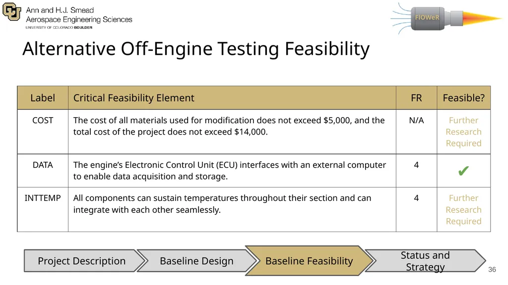
Alternative Off-Engine Testing Feasibility ‹#› Baseline Feasibility Baseline Design Status and Strategy Project Description<br>
37
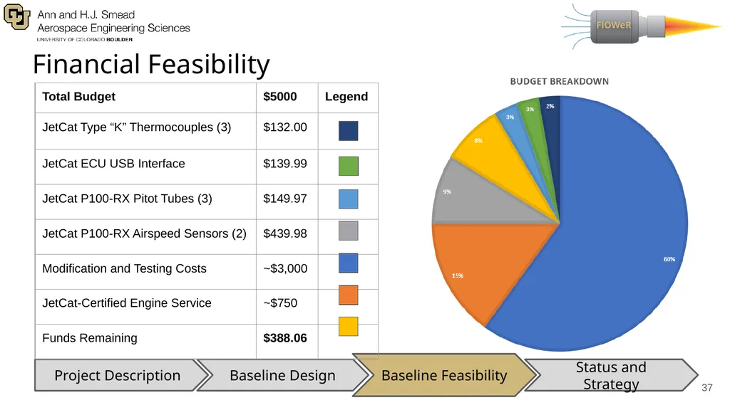
Financial Feasibility ‹#› Baseline Feasibility Baseline Design Status and Strategy Project Description<br>
38
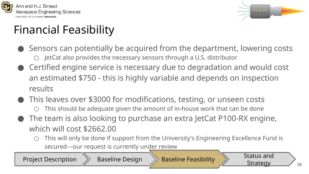
Financial Feasibility Sensors can potentially be acquired from the department, lowering costs
JetCat also provides the necessary sensors through a U.S. distributor
Certified engine service is necessary due to degradation and would cost an estimated $750 - this is highly variable and depends on inspection results
This leaves over $3000 for modifications, testing, or unseen costs
This should be adequate given the amount of in-house work that can be done
The team is also looking to purchase an extra JetCat P100-RX engine, which will cost $2662.00
This will only be done if support from the University's Engineering Excellence Fund is secured---our request is currently under review ‹#› Baseline Feasibility Baseline Design Status and Strategy Project Description<br>
39
Status and Strategy Status and Strategy Baseline Design Baseline Feasibility Project Description ‹#›<br>
40
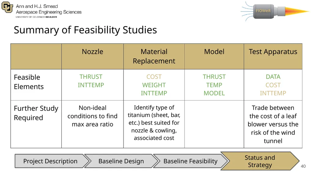
Summary of Feasibility Studies ‹#› Status and Strategy Baseline Design Baseline Feasibility Project Description<br>
41
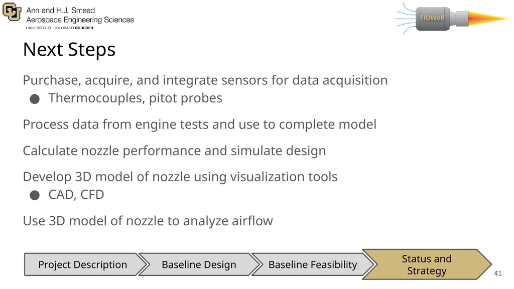
Next Steps ‹#› Status and Strategy Baseline Design Baseline Feasibility Project Description Purchase, acquire, and integrate sensors for data acquisition
Thermocouples, pitot probes
Process data from engine tests and use to complete model
Calculate nozzle performance and simulate design
Develop 3D model of nozzle using visualization tools
CAD, CFD
Use 3D model of nozzle to analyze airflow<br>
Thermocouples, pitot probes
Process data from engine tests and use to complete model
Calculate nozzle performance and simulate design
Develop 3D model of nozzle using visualization tools
CAD, CFD
Use 3D model of nozzle to analyze airflow<br>
42
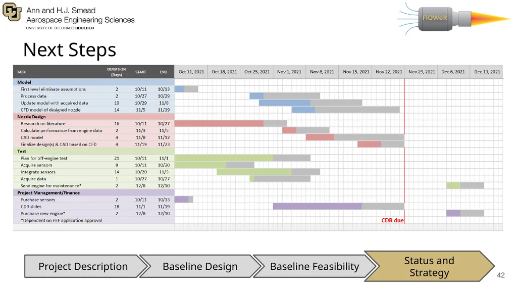
Next Steps ‹#› Status and Strategy Baseline Design Baseline Feasibility Project Description<br>
43
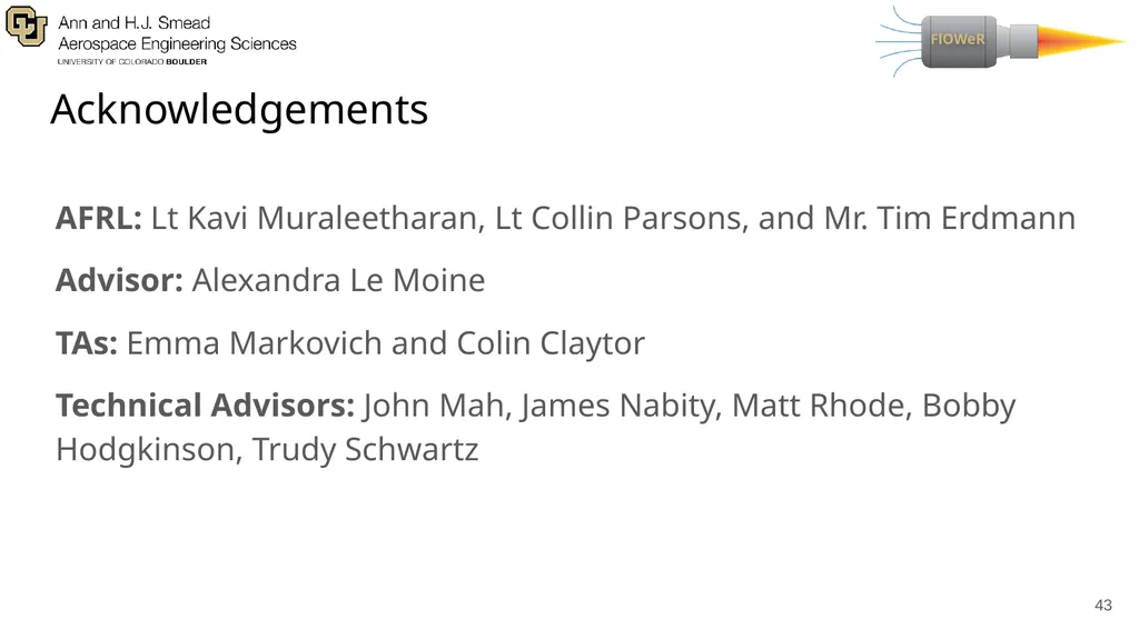
Acknowledgements AFRL: Lt Kavi Muraleetharan, Lt Collin Parsons, and Mr. Tim Erdmann
Advisor: Alexandra Le Moine
TAs: Emma Markovich and Colin Claytor
Technical Advisors: John Mah, James Nabity, Matt Rhode, Bobby Hodgkinson, Trudy Schwartz ‹#›<br>
Advisor: Alexandra Le Moine
TAs: Emma Markovich and Colin Claytor
Technical Advisors: John Mah, James Nabity, Matt Rhode, Bobby Hodgkinson, Trudy Schwartz ‹#›<br>
44
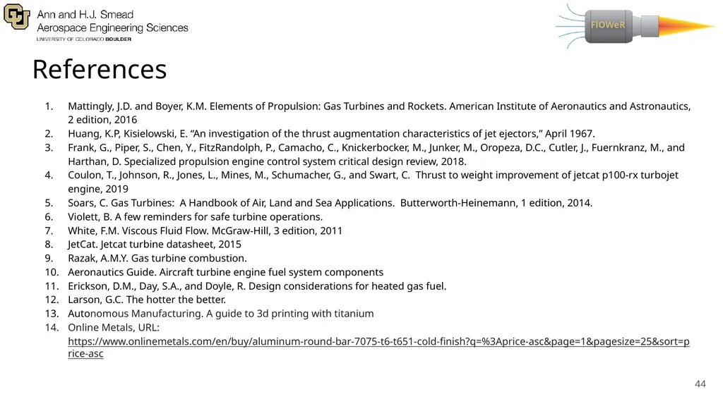
References Mattingly, J.D. and Boyer, K.M. Elements of Propulsion: Gas Turbines and Rockets. American Institute of Aeronautics and Astronautics, 2 edition, 2016
Huang, K.P, Kisielowski, E. “An investigation of the thrust augmentation characteristics of jet ejectors,” April 1967.
Frank, G., Piper, S., Chen, Y., FitzRandolph, P., Camacho, C., Knickerbocker, M., Junker, M., Oropeza, D.C., Cutler, J., Fuernkranz, M., and Harthan, D. Specialized propulsion engine control system critical design review, 2018.
Coulon, T., Johnson, R., Jones, L., Mines, M., Schumacher, G., and Swart, C. Thrust to weight improvement of jetcat p100-rx turbojet engine, 2019
Soars, C. Gas Turbines: A Handbook of Air, Land and Sea Applications. Butterworth-Heinemann, 1 edition, 2014.
Violett, B. A few reminders for safe turbine operations.
White, F.M. Viscous Fluid Flow. McGraw-Hill, 3 edition, 2011
JetCat. Jetcat turbine datasheet, 2015
Razak, A.M.Y. Gas turbine combustion.
Aeronautics Guide. Aircraft turbine engine fuel system components
Erickson, D.M., Day, S.A., and Doyle, R. Design considerations for heated gas fuel.
Larson, G.C. The hotter the better.
Autonomous Manufacturing. A guide to 3d printing with titanium
Online Metals, URL: https://www.onlinemetals.com/en/buy/aluminum-round-bar-7075-t6-t651-cold-finish?q=%3Aprice-asc&page=1&pagesize=25&sort=price-asc ‹#›<br>
45
Supplemental Material ‹#›<br>
46
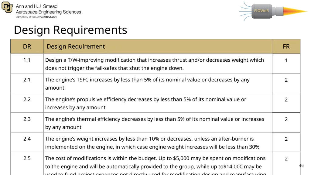
Design Requirements ‹#›<br>
47
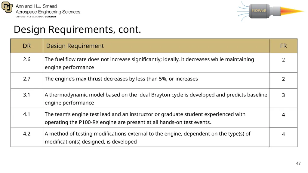
Design Requirements, cont. ‹#›<br>
48
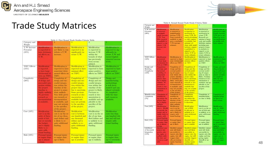
Trade Study Matrices ‹#›<br>
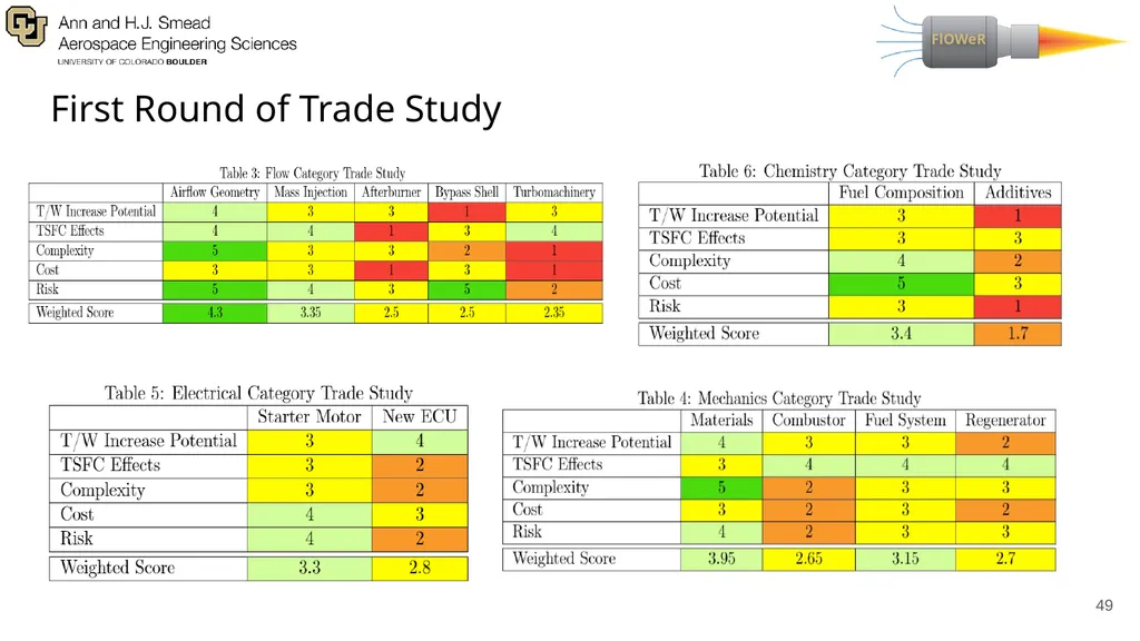
49
First Round of Trade Study ‹#›<br>
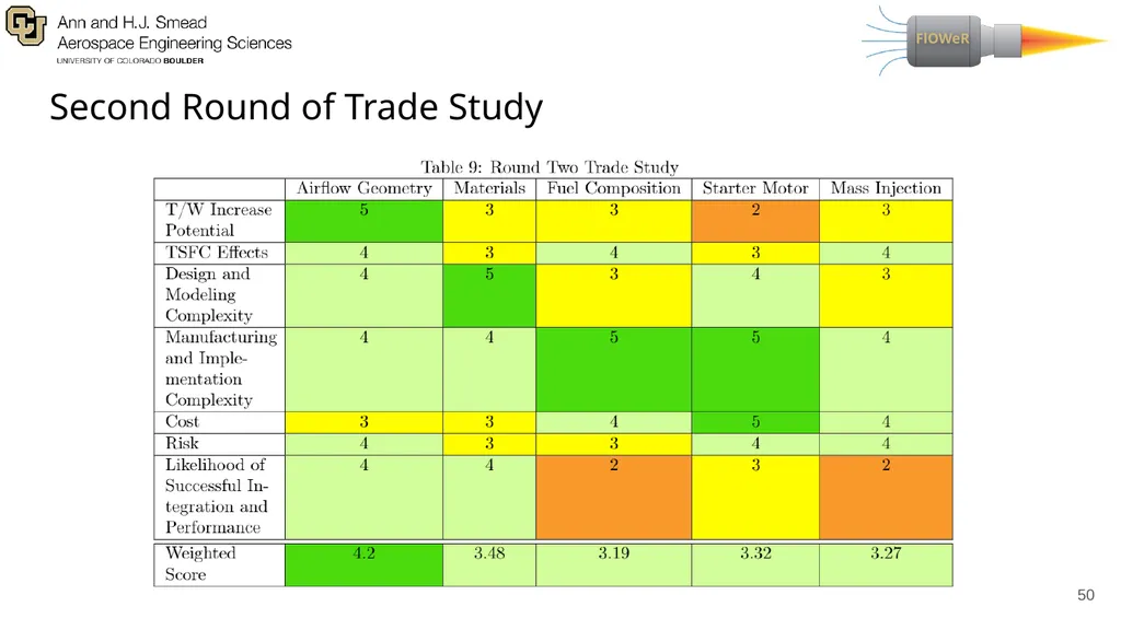
50
Second Round of Trade Study ‹#›<br>
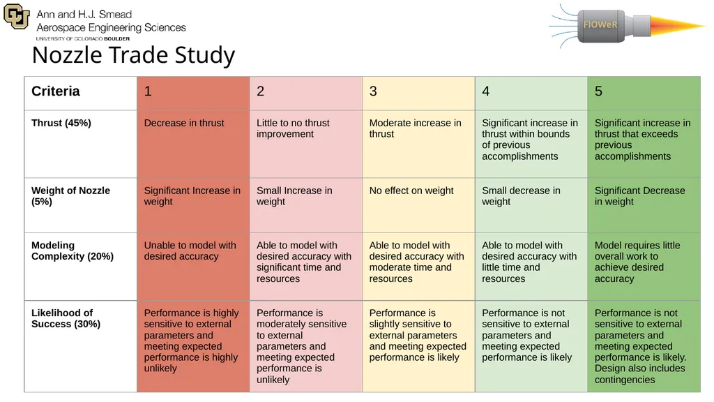
51
Nozzle Trade Study ‹#›<br>
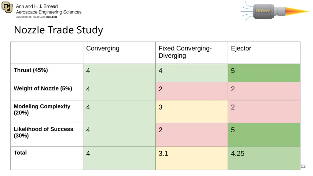
52
Nozzle Trade Study ‹#›<br>
53
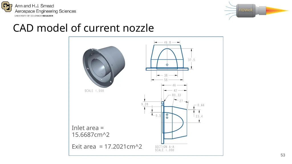
CAD model of current nozzle ‹#› Inlet area = 15.6687cm^2
Exit area = 17.2021cm^2<br>
Exit area = 17.2021cm^2<br>
54
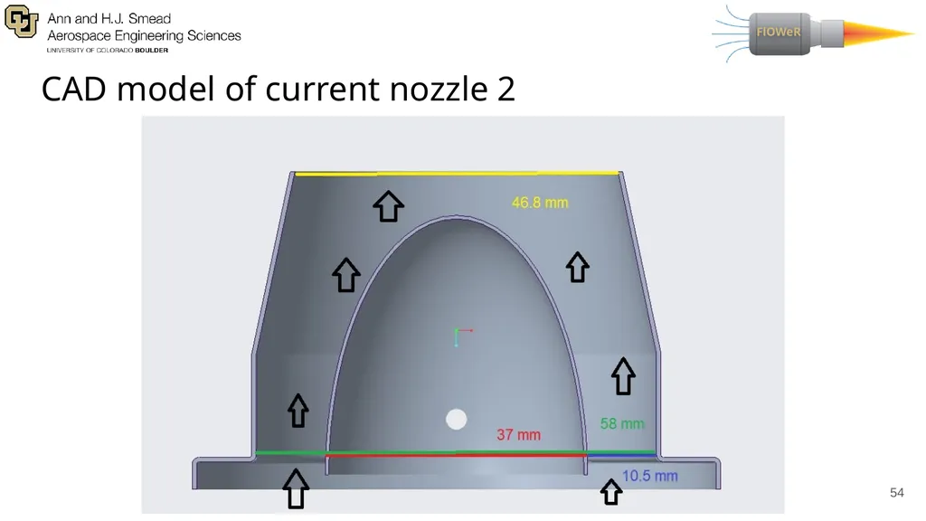
CAD model of current nozzle 2 ‹#› Inlet area = 15.6687cm^2
Exit area = 17.2021cm^2<br>
Exit area = 17.2021cm^2<br>
55
Material Replacement Thermal Stresses
Maximum temperature reached is approximately 1100 K in combustor
Tf = 1100K and Ti = 293K ‹#› 𝜎 = E𝛼(Tf - Ti )<br>
Maximum temperature reached is approximately 1100 K in combustor
Tf = 1100K and Ti = 293K ‹#› 𝜎 = E𝛼(Tf - Ti )<br>
56
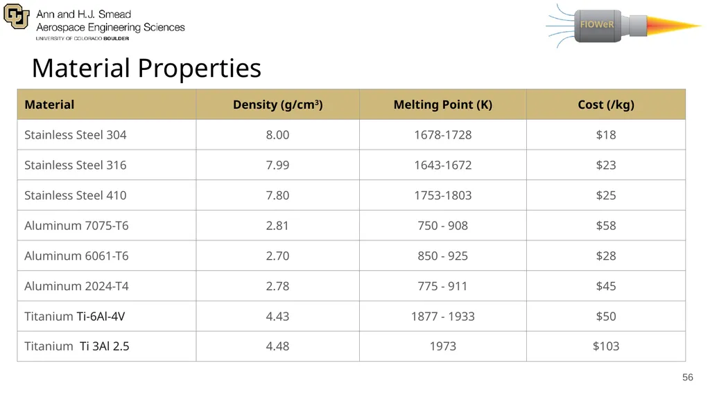
Material Properties ‹#›<br>
57
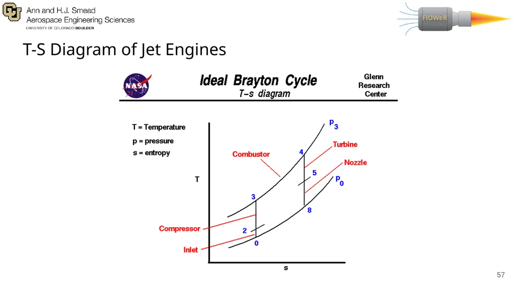
T-S Diagram of Jet Engines ‹#›<br>
58
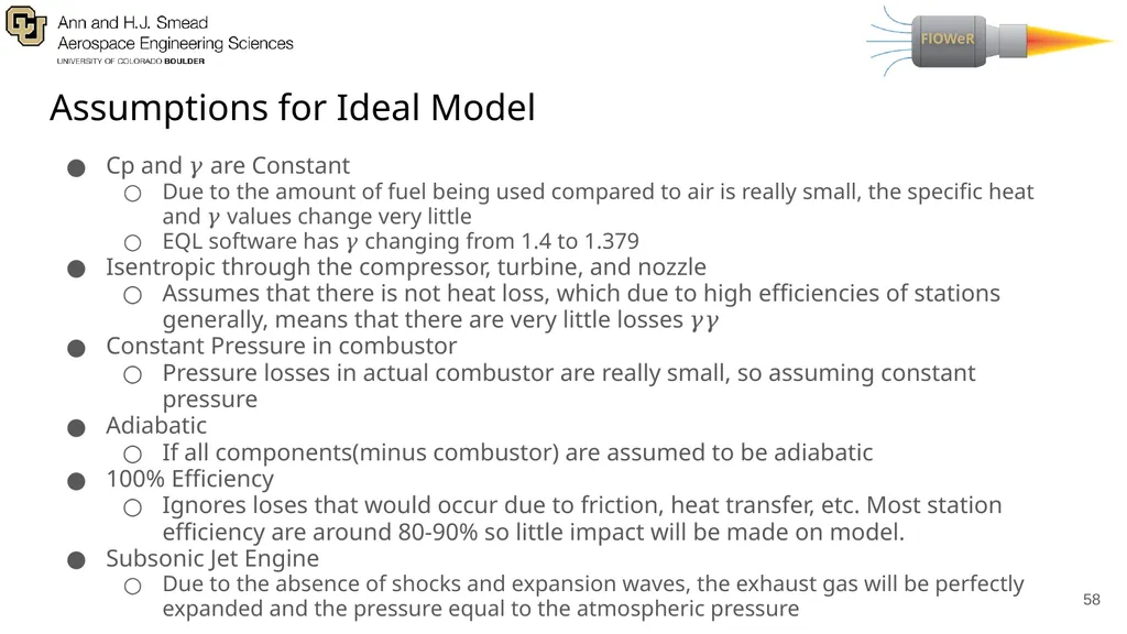
Assumptions for Ideal Model Cp and 𝛾 are Constant
Due to the amount of fuel being used compared to air is really small, the specific heat and 𝛾 values change very little
EQL software has 𝛾 changing from 1.4 to 1.379
Isentropic through the compressor, turbine, and nozzle
Assumes that there is not heat loss, which due to high efficiencies of stations generally, means that there are very little losses 𝛾𝛾
Constant Pressure in combustor
Pressure losses in actual combustor are really small, so assuming constant pressure
Adiabatic
If all components(minus combustor) are assumed to be adiabatic
100% Efficiency
Ignores loses that would occur due to friction, heat transfer, etc. Most station efficiency are around 80-90% so little impact will be made on model.
Subsonic Jet Engine
Due to the absence of shocks and expansion waves, the exhaust gas will be perfectly expanded and the pressure equal to the atmospheric pressure ‹#›<br>
59
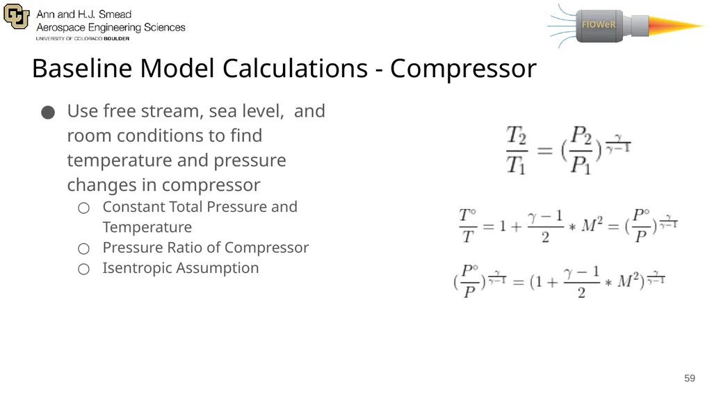
Baseline Model Calculations - Compressor Use free stream, sea level, and room conditions to find temperature and pressure changes in compressor
Constant Total Pressure and Temperature
Pressure Ratio of Compressor
Isentropic Assumption ‹#›<br>
Constant Total Pressure and Temperature
Pressure Ratio of Compressor
Isentropic Assumption ‹#›<br>
60
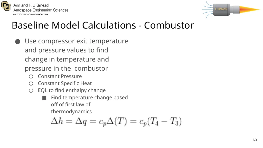
Baseline Model Calculations - Combustor Use compressor exit temperature and pressure values to find change in temperature and pressure in the combustor
Constant Pressure
Constant Specific Heat
EQL to find enthalpy change
Find temperature change based off of first law of thermodynamics ‹#›<br>
Constant Pressure
Constant Specific Heat
EQL to find enthalpy change
Find temperature change based off of first law of thermodynamics ‹#›<br>
61
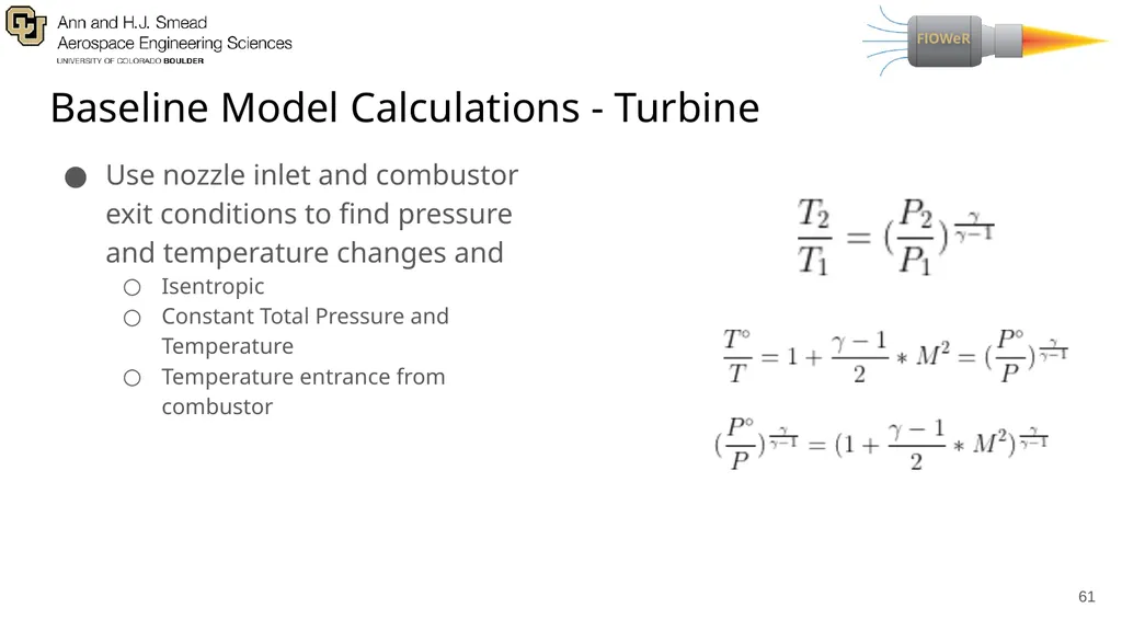
Baseline Model Calculations - Turbine Use nozzle inlet and combustor exit conditions to find pressure and temperature changes and
Isentropic
Constant Total Pressure and Temperature
Temperature entrance from combustor ‹#›<br>
Isentropic
Constant Total Pressure and Temperature
Temperature entrance from combustor ‹#›<br>
62
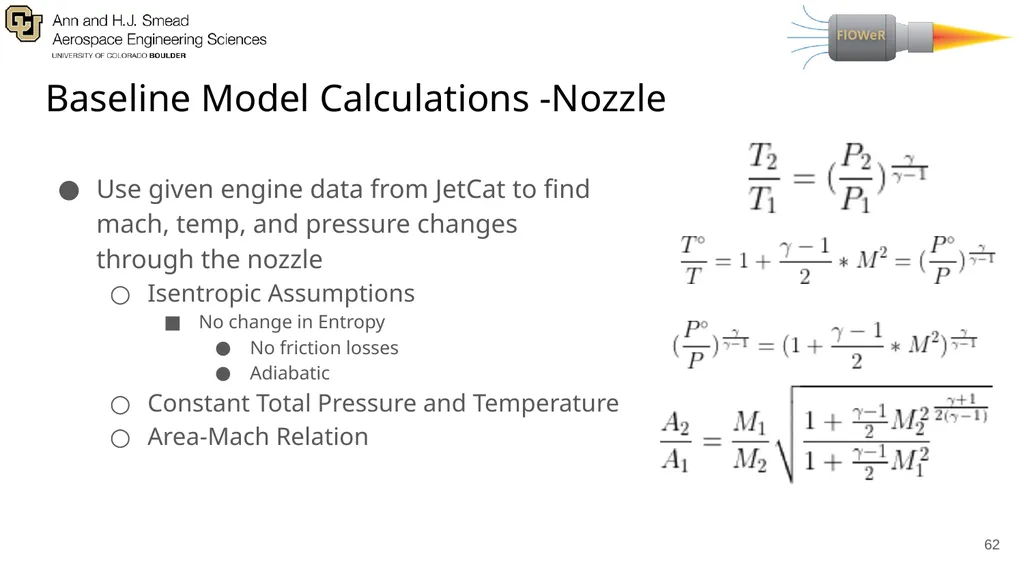
Baseline Model Calculations -Nozzle Use given engine data from JetCat to find mach, temp, and pressure changes through the nozzle
Isentropic Assumptions
No change in Entropy
No friction losses
Adiabatic
Constant Total Pressure and Temperature
Area-Mach Relation ‹#›<br>
Isentropic Assumptions
No change in Entropy
No friction losses
Adiabatic
Constant Total Pressure and Temperature
Area-Mach Relation ‹#›<br>
63
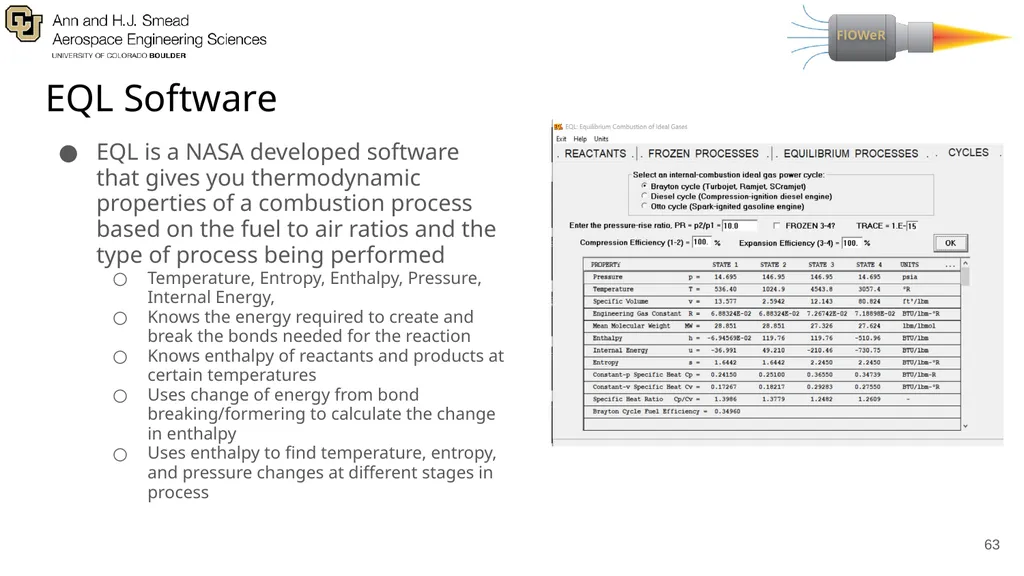
EQL Software EQL is a NASA developed software that gives you thermodynamic properties of a combustion process based on the fuel to air ratios and the type of process being performed
Temperature, Entropy, Enthalpy, Pressure, Internal Energy,
Knows the energy required to create and break the bonds needed for the reaction
Knows enthalpy of reactants and products at certain temperatures
Uses change of energy from bond breaking/formering to calculate the change in enthalpy
Uses enthalpy to find temperature, entropy, and pressure changes at different stages in process ‹#›<br>
64
Model Improvement Plan Steps to Improve current Model
Start to eliminate assumption
Acquire necessary sensors
Pitot tubes, thermocouples, IR Sensor/Camera
Attach sensors where measurements are needed
Pitot tube at the entrance and exit of engine,
Thermocouples before and after each station
IR sensor/Camera pointing at engine (Maybe)
Run engine and collect data
Verify that data makes sense compared to ideal model and follows similar trend
Rank assumptions based on biggest sources of errors
Remove assumptions that create significant errors
Use data obtained from engine, calculate total loses
Heat Transfer, Rayleigh flow losses, Efficiencies
Create new model
Design modifications based off of new model ‹#›<br>
65
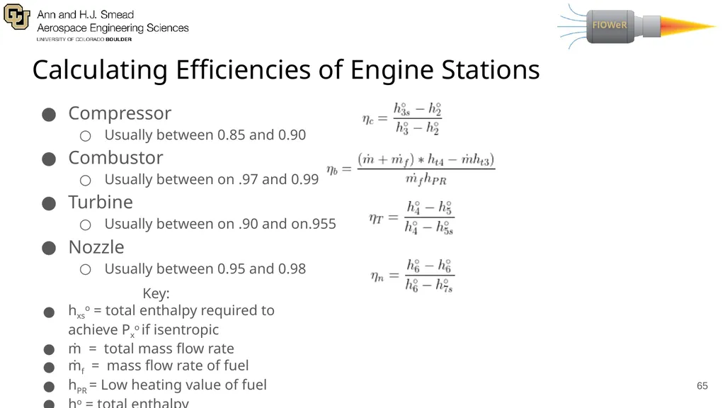
Calculating Efficiencies of Engine Stations Compressor
Usually between 0.85 and 0.90
Combustor
Usually between on .97 and 0.99
Turbine
Usually between on .90 and on.955
Nozzle
Usually between 0.95 and 0.98 ‹#› Key:
hxso = total enthalpy required to achieve Pxo if isentropic
ṁ = total mass flow rate
ṁf = mass flow rate of fuel
hPR = Low heating value of fuel
ho = total enthalpy<br>
66
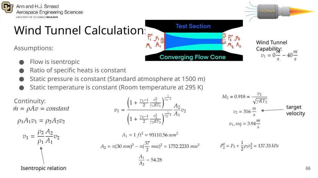
Wind Tunnel Calculations Assumptions:
Flow is isentropic
Ratio of specific heats is constant
Static pressure is constant (Standard atmosphere at 1500 m)
Static temperature is constant (Room temperature at 295 K)
Continuity: ‹#› Isentropic relation target
velocity Wind Tunnel Capability:<br>
Flow is isentropic
Ratio of specific heats is constant
Static pressure is constant (Standard atmosphere at 1500 m)
Static temperature is constant (Room temperature at 295 K)
Continuity: ‹#› Isentropic relation target
velocity Wind Tunnel Capability:<br>
67
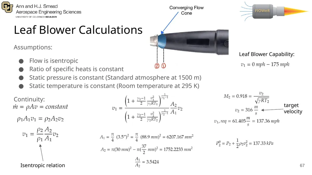
Leaf Blower Calculations ‹#› Assumptions:
Flow is isentropic
Ratio of specific heats is constant
Static pressure is constant (Standard atmosphere at 1500 m)
Static temperature is constant (Room temperature at 295 K)
Continuity: Isentropic relation target
velocity Leaf Blower Capability:<br>
Flow is isentropic
Ratio of specific heats is constant
Static pressure is constant (Standard atmosphere at 1500 m)
Static temperature is constant (Room temperature at 295 K)
Continuity: Isentropic relation target
velocity Leaf Blower Capability:<br>
68
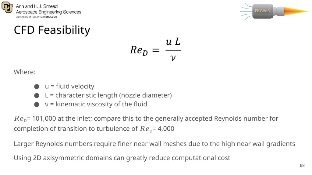
CFD Feasibility Where:
u = fluid velocity
L = characteristic length (nozzle diameter)
ν = kinematic viscosity of the fluid
𝑅𝑒D= 101,000 at the inlet; compare this to the generally accepted Reynolds number for completion of transition to turbulence of 𝑅𝑒D= 4,000
Larger Reynolds numbers require finer near wall meshes due to the high near wall gradients
Using 2D axisymmetric domains can greatly reduce computational cost ‹#›<br>
69
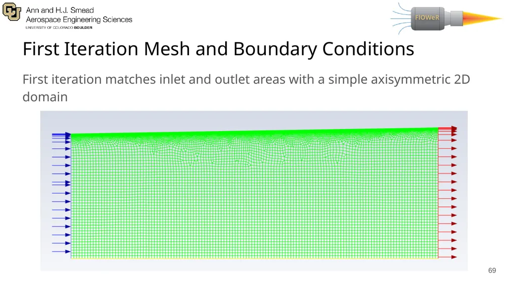
First Iteration Mesh and Boundary Conditions First iteration matches inlet and outlet areas with a simple axisymmetric 2D domain ‹#›<br>
70
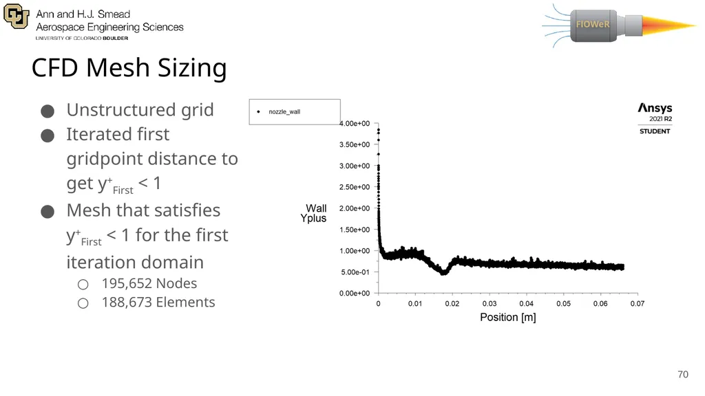
CFD Mesh Sizing Unstructured grid
Iterated first gridpoint distance to get y+First < 1
Mesh that satisfies y+First < 1 for the first iteration domain
195,652 Nodes
188,673 Elements ‹#›<br>
Iterated first gridpoint distance to get y+First < 1
Mesh that satisfies y+First < 1 for the first iteration domain
195,652 Nodes
188,673 Elements ‹#›<br>