
DLL 1 Syllabus Module II Data Link layer Design Issues Flow Control and ARQ techniques Data link Protocols HDLC DLL in Internet 2 Data Link Layer Design Issues Services Provided to the Network Layer ID: 999626
Download Presentation The PPT/PDF document "Module II The Data Link Layer" is the property of its rightful owner. Permission is granted to download and print the materials on this web site for personal, non-commercial use only, and to display it on your personal computer provided you do not modify the materials and that you retain all copyright notices contained in the materials. By downloading content from our website, you accept the terms of this agreement.


1. Module IIThe Data Link Layer(DLL)1
2. SyllabusModule II Data Link layer Design Issues – Flow Control and ARQ techniques. Data link Protocols – HDLC. DLL in Internet.2
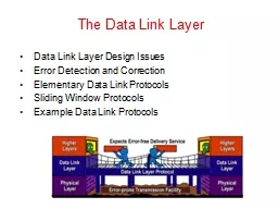
3. Data Link Layer Design IssuesServices Provided to the Network LayerFramingError ControlFlow Control3
4. Functions of the Data Link LayerProvide service interface to the network layerDealing with transmission errorsRegulating data flowSlow receivers not swamped by fast sendersDLL takes the packets it gets from the network layer and encapsulates them into frames for transmission. Each frame contains a frame header, a payload field for holding the packet, and a frame trailer. Frame management forms the heart of what the DLL do 4
5. Functions of the Data Link LayerRelationship between packets and frames.5
6. Services provided to the Network LayerTransfers data from the network layer on the source machine to the network layer on the destination machine(a) Virtual Communication.(b) Actual Communication.6
7. Services provided to the Network LayerDLL commonly provides 3 servicesUnacknowledged connectionless serviceAcknowledged connectionless serviceAcknowledged connection-oriented service7
8. Services provided to the Network LayerUnacknowledged connectionless serviceSource machine send independent frames to the destination machine without having the destination machine acknowledge them No logical connection is established If a frame is lost due to noise on the line, no attempt is made to detect the loss or recover from it This class of service is appropriate when the error rate is very low so that recovery is left to higher layers also appropriate for real-time traffic, such as voice, in which late data are worse than bad data Most LANs use unacknowledged connectionless service 8
9. Services provided to the Network LayerAcknowledged connectionless serviceno logical connections each frame sent is individually acknowledged sender knows whether a frame has arrived correctly If it has not arrived within a specified time interval, it can be sent again. This service is useful over unreliable channels, such as wireless systems If the average packet is broken up into, say, 10 frames, and 20 percent of all frames are lost, it may take a very long time for the packet to get through. If individual frames are acknowledged and retransmitted, entire packets get through much faster. 9
10. Services provided to the Network LayerAcknowledged connection-oriented serviceSource and destination machines establish a connection before any data are transferred. Each frame sent over the connection is numberedDLL guarantees that each frame sent is indeed received. it also guarantees that each frame is received exactly once and that all frames are received in the right order. With connectionless service, it is conceivable that a lost acknowledgement causes a packet to be sent several times and thus received several times 10
11. Services provided to the Network LayerAcknowledged connection-oriented serviceTransfer in 3 phasesPhase 1connection is established by having both sides initialize variables and counters needed to keep track of which frames have been received and which ones have not Phase 2one or more frames are actually transmitted Phase 3connection is released, freeing up the variables, buffers, and other resources used to maintain the connection 11
12. FramingDLL accepts bits from Physical layer and it detect and correct errors.DLL break the bit stream up into discrete frames and compute the checksum for each frameWhen a frame arrives at the destination, the checksum is recomputed. If the newly-computed checksum is different from the one contained in the frame, the DLL knows that an error has occurred and takes steps to deal with it e.g., discarding the bad frame and possibly also sending back an error report12
13. FramingBreaking the bit stream up into frames is more difficult than it appears One method is to insert time gaps between frames, much like the spaces between words in ordinary text.It is possible that these gaps might be squeezed out or other gaps might be inserted during transmission So, it is difficult to count on timing to mark the start and end of each frame Other methodsCharacter count. Flag bytes with byte stuffing. Starting and ending flags, with bit stuffing. Physical layer coding violations.13
14. Framing (Character count)Character countuses a field in the header to specify the number of characters in the frameWhen the DLL at the destination sees the character count, it knows how many characters follow and hence where the end of the frame is Eg: A character stream. (a) Without errors. (b) With one error.14
15. FramingCharacter countProblem with this algorithmcount can be garbled by a transmission error if the character count of 5 in the second frame becomes a 7, the destination will get out of synchronization destination will be unable to locate the start of the next frame even if the checksum is incorrectdestination does not know how many characters to skip over to get to the start of the retransmission So, character count method is rarely used 15
16. FramingFlag bytes with byte stuffingSolves the problem of resynchronization after an error by having each frame start and end with special bytesthe same byte, called a FLAG byte, as both the starting and ending delimiterif the receiver ever loses synchronization, it can just search for the flag byte to find the end of the current frame. Two consecutive flag bytes indicate the end of one frame and start of the next one16
17. Framing (Byte Stuffing)(a) A frame delimited by flag bytes.(b) Four examples of byte sequences before and after stuffing.17
18. FramingFlag bytes with byte stuffingProblem with this method:when binary data, such as object programs or floating-point numbers, are being transmitted. It may easily happen that the flag byte's bit pattern occurs in the dataSolution:is to have the sender's DLL insert a special escape byte (ESC) just before each ''accidental'' flag byte in the data. The DLL on the receiving end removes the escape byte before the data are given to the network layer. This technique is called byte stuffing or character stuffing. Thus, a framing flag byte can be distinguished from one in the data by the absence or presence of an escape byte before it18
19. FramingFlag bytes with byte stuffingIf an escape byte occurs in the middle of the data, it is also stuffed with an escape byte. Thus, any single escape byte is part of an escape sequence, whereas a doubled one indicates that a single escape occurred naturally in the data19
20. FramingStarting and ending flags, with bit stuffing a new technique developed to allow arbitrary sized charactersallows data frames to contain an arbitrary number of bits & allows character codes with an arbitrary number of bits per characterEach frame begins and ends with a special bit pattern, 01111110 (in fact, a flag byte). Whenever the sender's DLL encounters 5 consecutive 1s in the data, it automatically stuffs a 0 bit into the outgoing bit stream. 20
21. FramingStarting and ending flags, with bit stuffing When the receiver sees 5 consecutive incoming 1 bits, followed by a 0 bit, it automatically destuffs (i.e., deletes) the 0 bit. If the user data contain the flag pattern, 01111110, this flag is transmitted as 011111010 but stored in the receiver's memory as 01111110.21
22. Framing (Bit stuffing)Bit stuffing(a) The original data.(b) The data as they appear on the transmission line.(c) The data as they are stored in receiver’s memory after destuffing.22
23. Error ControlTo make sure all frames are eventually delivered to the network layer at the destination and in the proper order For reliable delivery, protocol calls for the receiver send back special control frames bearing positive or negative acknowledgements about the incoming frames Problem: hardware troubles may cause a frame to vanish completely (e.g., in a noise burst). Solution: by introducing timers into the DLL23
24. Error ControlUse of Timer in DLLWhen the sender transmits a frame, it generally also starts a timer. The timer is set to expire after an interval long enough for the frame to reach the destination, be processed there, and have the acknowledgement propagate back to the sender. acknowledgement will get back before the timer runs out in which case the timer will be canceled if either the frame or the acknowledgement is lost, the timer will go off, alerting the sender to a potential problem. The obvious solution is to just transmit the frame again Another Problem : receiving frames multiple timesSolution:to assign sequence numbers to outgoing frames, so that the receiver can distinguish retransmissions from originals24
25. Flow Controlhow to keep a fast sender from overloading a slow receiver with dataTwo approachesfeedback-based flow controlthe receiver sends back information to the sender giving it permission to send more data or at least telling the sender how the receiver is doingrate-based flow controlthe protocol has a built-in mechanism that limits the rate at which senders may transmit data, without using feedback from the receiverThe protocol contains well-defined rules about when a sender may transmit the next frame25
26. Error Detection and Correctionerrors on some media (e.g., radio) tend to come in bursts rather than singlyErrors in bursts has both advantages and disadvantages over isolated single-bit errors. Adv: computer data are always sent in blocks of bits. If the error rate is low, errors may occur in 1or 2 blocks only Disadv: they are much harder to correctError-Correcting Codes:Network designers have developed two basic strategies for dealing with errorsStrategy 1: uses error-correcting codesto include enough redundant information along with each block of data sent, to enable the receiver to deduce what the transmitted data must have been26
27. Error Detection and CorrectionError-Correcting Codes:Strategy 2: uses error-detecting codes to include only enough redundancy to allow the receiver to deduce that an error occurredhave to request a retransmission. The use of error-correcting codes is often referred to as forward error correction.Applications:On channels that are highly reliable, such as fiber, it is cheaper to use an error detecting code and just retransmit the occasional block found to be faulty. On channels such as wireless links that make many errors, it is better to use error correcting code rather than relying on a retransmission, which itself may be in error27
28. Error Detection and CorrectionTo understand how errors can be handled, it is necessary to look closely at what an error really isNormally, a frame consists of m data (i.e., message) bits and r redundant or check bits. Let the total length be n (i.e., n = m + r). An n-bit unit containing data and check bits is often referred to as an n-bit codewordGiven any two codewords, say, 10001001 and 10110001, it is possible to determine how many corresponding bits differ. In this case, 3 bits differ. To determine how many bits differ, just exclusive OR the two codewords and count the number of 1 bits in the result28
29. Error Detection and CorrectionThe number of bit positions in which two codewords differ is called the Hamming distanceif two codewords are a Hamming distance ‘d’ apart, it will require ‘d’ single-bit errors to convert one into the otherall 2m possible data messages are legal, but due to the way the check bits are computed, not all of the 2n possible codewords are usedGiven the algorithm for computing the check bits, it is possible to construct a complete list of the legal codewords, and from this list, find the two codewords whose Hamming distance is minimumerror-detecting and error-correcting properties of a code depend on its Hamming distance29
30. Error Detection and CorrectionTo detect d errors, We need a distance d + 1 code because with such a code there is no way that d single-bit errors can change a valid codeword into another valid codeword. When the receiver sees an invalid codeword, it can tell that a transmission error has occurred. To correct d errors, We need a distance 2d + 1 code because that way the legal codewords are so far apart that even with d changes, the original codeword is still closer than any other codeword, so it can be uniquely determined.30
31. Error DetectionEg for error detectionconsider a code in which a single parity bit is appended to the data. The parity bit is chosen so that the number of 1 bits in the codeword is even (or odd). For example, when 1011010 is sent in even parity, a bit is added to the end to make it 10110100. With odd parity 1011010 becomes 10110101. A code with a single parity bit has a distance 2, since any single-bit error produces a codeword with the wrong parity. Eg: In even Parity, if there is error in 3rd bit of 10110100 as 10010100, the distance is 2 1011010010010100 wrong parityIt can be used to detect single errors.31
32. Error CorrectionEg for error correctionconsider a code with only four valid codewords: 0000000000, 0000011111, 1111100000, and 1111111111 This code has a distance 5, which means that it can correct double (2 * 2 + 1 = 5) errors. If the codeword 0000000111 arrives, the receiver knows that the original must have been 0000011111. If, however, a triple (2 * 3 + 1 = 7) error changes 0000000000 into 0000000111, the error will not be corrected properly 32
33. Error CorrectionSingle bit Error Correction using Hamming codeCalculating the Hamming Code The key to the Hamming Code is the use of extra parity bits to allow the identification of a single error. Creating the code word is as follows: Mark all bit positions that are powers of two as parity bits. (positions 1, 2, 4, 8, 16, 32, 64, etc.) All other bit positions are for the data to be encoded. (positions 3, 5, 6, 7, 9, 10, 11, 12, 13, 14, 15, 17, etc.) Each parity bit calculates the parity for some of the bits in the code word. 33
34. Error CorrectionThe position of the parity bit determines the sequence of bits that it alternately checks and skips.Position 1: check 1 bit, skip 1 bit, check 1 bit, skip 1 bit, etc. (1,3,5,7,9,11,13,15,...)Position 2: check 2 bits, skip 2 bits, check 2 bits, skip 2 bits, etc. (2,3,6,7,10,11,14,15,...)Position 4: check 4 bits, skip 4 bits, check 4 bits, skip 4 bits, etc. (4,5,6,7,12,13,14,15,20,21,22,23,...)Position 8: check 8 bits, skip 8 bits, check 8 bits, skip 8 bits, etc. (8-15,24-31,40-47,...)Set a parity bit to 1 if the total number of ones in the positions it checks is odd. Set a parity bit to 0 if the total number of ones in the positions it checks is even. 34
35. Error CorrectionExample: A byte of data: 10011010Create the codeword, leaving spaces for the parity bits: _ _ 1 _ 0 0 1 _ 1 0 1 0Calculate the parity for each parity bit : Position 1 checks bits 1,3,5,7,9,11: ? _ 1 _ 0 0 1 _ 1 0 1 0. Even parity so set position 1 to a 0: 0 _ 1 _ 0 0 1 _ 1 0 1 0 Position 2 checks bits 2,3,6,7,10,11:0 ? 1 _ 0 0 1 _ 1 0 1 0. Odd parity so set position 2 to a 1: 0 1 1 _ 0 0 1 _ 1 0 1 0 Position 4 checks bits 4,5,6,7,12:0 1 1 ? 0 0 1 _ 1 0 1 0. Odd parity so set position 4 to a 1: 0 1 1 1 0 0 1 _ 1 0 1 0 35
36. Error CorrectionPosition 8 checks bits 8,9,10,11,12:0 1 1 1 0 0 1 ? 1 0 1 0. Even parity so set position 8 to a 0: 0 1 1 1 0 0 1 0 1 0 1 0 So the Code word is 011100101010. Finding and fixing a single bit error Suppose the word that was received was 011100101110 instead. Then the receiver could calculate which bit was wrong and correct it. The method is to verify each check bit. Write down all the incorrect parity bits. Doing so, we will discover which parity bits are incorrect.In general, check each parity bit and add the positions that are wrong, this will give you the location of the bad bit. 36
37. Error Correction0 1 1 1 0 0 1 0 1 1 1 0Position 1 checks bits 1,3,5,7,9,11: Even Parity so 0 in position 1 is correct0 1 1 1 0 0 1 0 1 1 1 0Position 2 checks bits 2,3,6,7,10,11: Even Parity so 0 must be added to position 2 & is incorrect0 1 1 1 0 0 1 0 1 1 1 0Position 4 checks bits 4,5,6,7,12:Odd Parity so 4 in position 4 is correct0 1 1 1 0 0 1 0 1 1 1 0Position 8 checks bits 8,9,10,11,12:Odd Parity so 1 must be added to position 8 & is incorrect Positions 2 & 8 are incorrect. Adding these, we get 10 & it is the position where the error occurred & it can be corrected37
38. Error-Correcting Codes38
39. Error CorrectionHamming codes can only correct single errors. However, there is a trick that can be used to permit Hamming codes to correct burst errors. A sequence of k consecutive codewords are arranged as a matrix, one codeword per row. Normally, the data would be transmitted one codeword at a time, from left to right. To correct burst errors, the data should be transmitted one column at a time, starting with the leftmost column. When all k bits have been sent, the second column is sent, and so on39
40. Error CorrectionWhen the frame arrives at the receiver, the matrix is reconstructed, one column at a time. If a burst error of length k occurs, at most 1 bit in each of the k codewords will have been affected, but the Hamming code can correct one error per codeword, so the entire block can be restored. This method uses kr check bits to make blocks of km data bits immune to a single burst error of length k or less.40
41. Error DetectionUsing copper wire or fiber, the error rate is much lowerso error detection and retransmission is usually more efficient for dealing with the occasional error consider a channel on which errors are isolated and the error rate is 10-6 per bit. Let the block size be 1000 bits. To provide error correction for 1000-bit blocks, 10 check bits are needed at 1,2,4,8,16,32,64,128,256,512 bit locations; a megabit of data would require 10,000 check bits. To merely detect a block with a single 1-bit error, one parity bit per block will be sufficient. Once every 1000 blocks, an extra block (1001 bits) will have to be transmitted. The total overhead for the error detection + retransmission method is only 2001 bits per megabit of data, versus 10,000 bits for a Hamming code. 41
42. Error DetectionIf a single parity bit is added to a block and the block is badly garbled by a long burst error, the probability that the error will be detected is only 0.5, which is hardly acceptable. The odds can be improved considerably if each block to be sent is regarded as a rectangular matrix n bits wide and k bits highA parity bit is computed separately for each column and affixed to the matrix as the last row. The matrix is then transmitted one row at a time. When the block arrives, the receiver checks all the parity bits. If any one of them is wrong, the receiver requests a retransmission of the block. Additional retransmissions are requested as needed until an entire block is received without any parity errors This method can detect a single burst of length n, since only 1 bit per column will be changed 42
43. Error DetectionIf the block is badly garbled by a long burst or by multiple shorter bursts, the probability that any of the n columns will have the correct parity, by accident, is 0.5so the probability of a bad block being accepted when it should not be is 2-nThis scheme is adequate (sufficient) in practiceAnother method is in widespread use: the polynomial code, also known as a CRC (Cyclic Redundancy Check) Polynomial codes are based upon treating bit strings as representations of polynomials with coefficients of 0 and 1 only A k-bit frame is regarded as the coefficient list for a polynomial with k terms, ranging from xk - 1 to x0 43
44. Error DetectionSuch a polynomial is said to be of degree k - 1. The high-order (leftmost) bit is the coefficient of xk - 1; the next bit is the coefficient of xk - 2, and so on. For example, 110001 has 6 bits and thus represents a six-term polynomial with coefficients 1, 1, 0, 0, 0, and 1: x5 + x4 + x0Polynomial arithmetic is done modulo 2, according to the rules of algebraic field theory. There are no carries for addition or borrows for subtraction. Both addition and subtraction are identical to exclusive OR. 44
45. Error DetectionWhen the polynomial code method is employed, the sender and receiver must agree upon a generator polynomial, G(x), in advance. Both the high- and low-order bits of the generator must be 1. To compute the checksum for some frame with m bits, corresponding to the polynomial M(x), the frame must be longer than the generator polynomial. The idea is to append a checksum to the end of the frame in such a way that the polynomial represented by the checksummed frame is divisible by G(x). When the receiver gets the checksummed frame, it tries dividing it by G(x). If there is a remainder, there has been a transmission error. 45
46. Error DetectionThe algorithm for computing the checksum is as follows: 1. Let r be the degree of G(x). Append r zero bits to the low-order end of the frame so it now contains m + r bits and corresponds to the polynomial xMr(x). 2. Divide the bit string corresponding to G(x) into the bit string corresponding to xMr(x), using modulo 2 division. 3. Subtract the remainder (which is always r or fewer bits) from the bit string corresponding to xMr(x) using modulo 2 subtraction. The result is the checksummed frame to be transmitted. Call its polynomial T(x). 46
47. Error-Detecting CodesFig: Illustrates the calculation for a frame 1101011011 using the generator G(x) = x4 + x + 147
48. Error-Detecting CodesFig: Illustrates the calculation for a frame 1101011011 using the generator G(x) = x4 + x + 1 1 1 0 0 0 0 1 0 1 0 1 0 0 1 1 1 1 0 1 0 1 1 0 1 1 1 1 1 0 1 0 0 1 1 1 0 0 1 1 1 0 0 1 1 0 0 0 0 1 0 0 0 0 0 0 0 0 1 0 0 0 0 0 0 0 0 1 0 1 0 0 0 0 0 0 1 0 1 1 0 0 0 0 0 1 0 1 1 1 1 0 0 1 1 0 1 0 0 1 0 0 0 0 0 1 0 0 1 1 1 0 0 1 1 0 0 0 0 0 0 0 0 0 0 0 0 0 0Remainder is 0, so no errors 48
49. Elementary Data Link ProtocolsAn Unrestricted Simplex ProtocolA Simplex Stop-and-Wait ProtocolA Simplex Protocol for a Noisy Channel49
50. Elementary Data Link ProtocolsAn Unrestricted Simplex Protocolconsider a protocol that is as simple as it can beSimplex - Data are transmitted in one direction only. Both the transmitting and receiving network layers are always ready. Processing time can be ignored. Infinite buffer space is available. Communication channel between the data link layers never damages or loses frames. This is thoroughly an unrealistic protocol, so it is nicknamed as “utopia” 50
51. Elementary Data Link ProtocolsAn Unrestricted Simplex ProtocolThe protocol consists of two distinct procedures, a sender and a receiverThe sender runs in DLL of the source machine and the receiver run in the DLL of the destination machineNo sequence numbers or ACKs are used.The only event possible is frame-arrival51
52. Protocol DefinitionsSome definitions needed in the protocols .These are located in the file protocol.h52
53. Elementary Data Link ProtocolsAn Unrestricted Simplex Protocolvoid sender1(void) { frame s; //buffer for an outbound frame packet buffer; //buffer for an outbound packet while(true) { from_network_layer(&buffer); //get something to send s.info=buffer; //copy it to ‘s.info’ to_physical_layer(&s); //sent it } }53
54. Elementary Data Link ProtocolsAn Unrestricted Simplex Protocolvoid receiver 1(void) { frame r; event_type event; while(true) { wait_for_event(&event); //only possibility is frame arrival from_physical_layer(&r); //get the inbound frame to_network_layer(&r.info); //pass the data to the N/W layer } }54
55. Elementary Data Link ProtocolsA Simplex Stop-and-Wait Protocol Better solution:-Feedback (Dummy Frame) to the senderProtocols in which the sender sends one frame and then waits for an acknowledgment before proceeding are called Stop-and-Wait Protocol55
56. Elementary Data Link ProtocolsA Simplex Stop-and-Wait Protocol void sender2(void){ frame s; //buffer for an outbound frame Packet buffer; //buffer for an outbound packet Event-type event; //frame-arrival While(true) { from-network-layer(&buffer); s.info=buffer; to-physical-layer(&s); wait-for-event(&event); //wait for dummy frame }}56
57. Elementary Data Link ProtocolsA Simplex Stop-and-Wait Protocol void receiver2(void){ frame s ,r; //buffer for frames event-type event; //frame-arrival while(true) { wait-for-event(&event); from-physical-layer(&r); to-network-layer(&r.info); to-physical-layer(&s); //send a dummy Frame }}57
58. Elementary Data Link ProtocolsA Simplex Protocol for a Noisy Channel Consider the normal situation of a communication channel that makes errors Frames may be either damaged or lost completelywe assume that if a frame is damaged in transit, the receiver hardware will detect this when it computes the checksum Discarded damaged frame can be made available by resending the frame when a timer times out. But this will not assure the network layer about the packet lost or duplicatedata link layer must guarantee that no combination of transmission errors can cause a duplicate packet to be delivered to a network layer 58
59. Elementary Data Link ProtocolsA Simplex Protocol for a Noisy Channel to distinguish a frame that it is seeing for the first time from a retransmission By having the sender put a sequence number in the header of each frame it sends. the receiver can check the sequence number of each arriving frame to see if it is a new frame or a duplicate to be discarded What is the minimum number of bits needed for the sequence number? only uncertainty in this protocol is between a frame, m, and its direct successor, m + 1 The event that triggers the sender to start sending frame m + 2 is the arrival of an acknowledgement for frame m + 1.This implies that m has been correctly received 59
60. Elementary Data Link ProtocolsA Simplex Protocol for a Noisy Channel Protocols in which the sender waits for a positive acknowledgement before advancing to the next data item are often called PAR (Positive Acknowledgement with Retransmission) or ARQ (Automatic Repeat reQuest). The sender remembers the sequence number of the next frame to send in next_frame_to_send; the receiver remembers the sequence number of the next frame expected in frame_expected. 60
61. Elementary Data Link ProtocolsA Simplex Protocol for a Noisy Channel Sender protocol: After transmitting a frame and starting the timer, the sender waits for something to happen. Only three possibilities exist: an acknowledgement frame arrives undamaged, a damaged acknowledgement frame staggers in, or the timer expires. If a valid acknowledgement comes in, the sender fetches the next packet from its network layer and puts it in the buffer, overwriting the previous packet. It also advances the sequence number. If a damaged frame arrives or no frame at all arrives, neither the buffer nor the sequence number is changed so that a duplicate can be sent. 61
62. Elementary Data Link ProtocolsA Simplex Protocol for a Noisy Channel Receiver Protocol:When a valid frame arrives at the receiver, its sequence number is checked to see if it is a duplicate. If not, it is accepted, passed to the network layer, and an acknowledgement is generated. Duplicates and damaged frames are not passed to the network layer 62
63. A Simplex Protocol for a Noisy ChannelPAR or ARQ Protocol63
64. A Simplex Protocol for a Noisy Channel64
65. Sliding Window ProtocolsIn the previous protocols, data frames were transmitted in one direction only. In most practical situations, there is a need for transmitting data in both directions. One way of achieving full-duplex data transmission is to have two separate communication channels and use each one for simplex data traffic (in different directions). If this is done, we have two separate physical circuits, each with a ''forward'' channel (for data) and a ''reverse'' channel (for acknowledgements). In which cases, the bandwidth of the reverse channel is almost entirely wasted. In effect, the user is paying for two circuits but using only the capacity of one A better idea is to use the same circuit for data in both directions. 65
66. Sliding Window ProtocolsData frames from A to B are intermixed with the acknowledgement frames from A to B. By looking at the kind field in the header of an incoming frame, the receiver can tell whether the frame is data or acknowledgement Another improvement is possible: When a data frame arrives, instead of immediately sending a separate control frame, the receiver restrains itself and waits until the network layer passes it the next packet. The acknowledgement is attached to the outgoing data frame (using the ack field in the frame header). In effect, the acknowledgement gets a free ride on the next outgoing data frame. The technique of temporarily delaying outgoing acknowledgements so that they can be hooked onto the next outgoing data frame is known as piggybacking66
67. Sliding Window ProtocolsThe principal advantage of using piggybacking over having distinct acknowledgement frames better use of the available channel bandwidth. The ack field in the frame header costs only a few bits, whereas a separate frame would need a header, the acknowledgement, and a checksum. Other advantages:In addition, fewer frames sent means fewer ''frame arrival'' interrupts, fewer buffers required in the receiver, depending on how the receiver's software is organized. 67
68. Sliding Window ProtocolsPiggybacking introduces a complication not present with separate acknowledgements. How long should the data link layer wait for a packet onto which to piggyback the acknowledgement? If the data link layer waits longer than the sender's timeout period, the frame will be retransmitted, defeating the whole purpose of having acknowledgements. Of course, the data link layer cannot foretell the futureSo it must take an option to use a scheme, such as waiting a fixed number of milliseconds. If a new packet arrives quickly, the acknowledgement is piggybacked onto it; otherwise, if no new packet has arrived by the end of this time period, the data link layer just sends a separate acknowledgement frame 68
69. Sliding Window ProtocolsIn all sliding window protocols, each outbound frame contains a sequence number, ranging from 0 up to some maximum Maximum is usually 2n - 1 so the sequence number fits exactly in an n-bit field. The stop-and-wait sliding window protocol uses n = 1, restricting the sequence numbers to 0 and 1 Essence of all sliding window protocols at any instant of time, the sender maintains a set of sequence numbers corresponding to frames it is permitted to send. These frames are said to fall within the sending window. Similarly, the receiver also maintains a receiving window corresponding to the set of frames it is permitted to accept. 69
70. Sliding Window ProtocolsA sliding window of size 1, with a 3-bit sequence number.(a) Initially.(b) After the first frame has been sent.(c) After the first frame has been received.(d) After the first acknowledgement has been received.70
71. Sliding Window ProtocolsThe sender's window and the receiver's window need not have the same lower and upper limits or even have the same size. In some protocols they are fixed in size, but in others they can grow or shrink over the course of time as frames are sent and received The sequence numbers within the sender's window represent frames that have been sent or can be sent but are as yet not acknowledged. Whenever a new packet arrives from the network layer, it is given the next highest sequence number, and the upper edge of the window is advanced by one. When an acknowledgement comes in, the lower edge is advanced by one. In this way the window continuously maintains a list of unacknowledged frames. Since frames currently within the sender's window may ultimately be lost or damaged in transit, the sender must keep all these frames in its memory for possible retransmission.71
72. Sliding Window Protocols Thus, if the maximum window size is n, the sender needs n buffers to hold the unacknowledged frames. If the window ever grows to its maximum size, the sending data link layer must forcibly shut off the network layer until another buffer becomes free The receiver window corresponds to the frames it may accept. Any frame falling outside the window is discarded without comment. When a frame whose sequence number is equal to the lower edge of the window is received, it is passed to the network layer, an acknowledgement is generated, and the window is rotated by one. Unlike the sender's window, the receiver's window always remains at its initial size. Note that a window size of 1 means that the data link layer only accepts frames in order, but for larger windows this is not so. 72
73. Sliding Window ProtocolsBidirectional ProtocolsA One-Bit Sliding Window ProtocolA Protocol Using Go Back NA Protocol Using Selective RepeatThree protocols differ among themselves in terms of efficiency, complexity, and buffer requirements 73
74. A One-Bit Sliding Window ProtocolA sliding window protocol with a maximum window size of 1. Such a protocol uses stop-and-wait since the sender transmits a frame and waits for its acknowledgement before sending the next one starting machine fetches the first packet from its network layer, builds a frame from it, and sends it. When this frame arrives, the receiving data link layer checks to see if it is a duplicate If the frame is the one expected, it is passed to the network layer and the receiver's window is slid up 74
75. A One-Bit Sliding Window ProtocolThe acknowledgement field contains the number of the last frame received without error.If this number agrees with the sequence number of the frame the sender is trying to send, the sender knows it is done with the frame stored in buffer and can fetch the next packet from its network layer. If the sequence number disagrees, it must continue trying to send the same frame. 75
76. A One-Bit Sliding Window ProtocolScenario (a) Normal case. The notation is (seq, ack, packet number). An asterisk indicates where a network layer accepts a packet.76
77. A One-Bit Sliding Window ProtocolScenario (b) Abnormal case . The notation is (seq, ack, packet number). An asterisk indicates where a network layer accepts a packet.77
78. Until now we have made the assumption that the transmission time required for a frame to arrive at the receiver plus the transmission time for the acknowledgement to come back is negligible. Sometimes this assumption is clearly false. In these situations the long round-trip time can have important implications for the efficiency of the bandwidth utilization. The need for a large window on the sending side occurs whenever the product of bandwidth x round-trip-delay is large. The product of these two factors basically tells what the capacity of the pipe is, and the sender needs the ability to fill it without stopping in order to operate at peak efficiency This technique is known as pipelining.Sliding Window Protocol Using Go Back N78
79. Pipelining frames over an unreliable communication channel raises some serious issues. First, what happens if a frame in the middle of a long stream is damaged or lost? Large numbers of succeeding frames will arrive at the receiver before the sender even finds out that anything is wrong. When a damaged frame arrives at the receiver, it obviously should be discarded, but what should the receiver do with all the correct frames following it? Remember that the receiving DLL is required to hand packets to the network layer in sequence.Sliding Window Protocol Using Go Back N79
80. Two basic approaches are available for dealing with errors in the presence of pipelining. One way, called go back n, is for the receiver simply to discard all subsequent frames, sending no acknowledgements for the discarded frames. This strategy corresponds to a receive window of size 1. In other words, the DLL refuses to accept any frame except the next one it must give to the network layer. If the sender's window fills up before the timer runs out, the pipeline will begin to empty. Eventually, the sender will time out and retransmit all unacknowledged frames in order, starting with the damaged or lost one. This approach can waste a lot of bandwidth if the error rate is high.Sliding Window Protocol Using Go Back N80
81. Pipelining and error recovery. Effect on an error when receiver’s window size is 1 Frames 0 and 1 are correctly received and acknowledged. Frame 2, however, is damaged or lost. The sender, unaware of this problem, continues to send frames until the timer for frame 2 expires. Then it backs up to frame 2 and starts all over with it, sending 2, 3, 4, etc. all over againSliding Window Protocol Using Go Back N81
82. Other general strategy for handling errors when frames are pipelined is called selective repeat. When it is used, a bad frame that is received is discarded, but good frames received after it are buffered. When the sender times out, only the oldest unacknowledged frame is retransmitted. If that frame arrives correctly, the receiver can deliver to the network layer, in sequence, all the frames it has buffered. Selective repeat is often combined with having the receiver send a negative acknowledgement (NAK) when it detects an error, for example, when it receives a checksum error or a frame out of sequence. NAKs stimulate retransmission before the corresponding timer expires and thus improve performanceSliding Window Protocol Using Selective Repeat82
83. Pipelining and error recovery. Effect on an error when receiver’s window size is large. Selective repeat corresponds to a receiver window larger than 1 require large amounts of data link layer memory if the window is large83452Sliding Window Protocol Using Selective Repeat
84. Frames 0 and 1 are again correctly received and acknowledged and frame 2 is lost. When frame 3 arrives at the receiver, the DLL notices that is has missed a frame So it sends back a NAK for 2 but buffers 3. When frames 4 and 5 arrive, they, too, are buffered by the DLL instead of being passed to the network layer. Eventually, the NAK 2 gets back to the sender, which immediately resends frame 2. When that arrives, the DLL now has 2, 3, 4, and 5 and can pass all of them to the network layer in the correct order. It can also acknowledge all frames up to and including 5 If the NAK should get lost, eventually the sender will time out for frame 2 and send it, but that may be a quite a while later 84Sliding Window Protocol Using Selective Repeat
85. Multiple outstanding frames logically needs multiple timers, one per outstanding frame. Each frame times out independently of all the other ones. All of these timers can easily be simulated in software, using a single hardware clock that causes interrupts periodically. The pending timeouts form a linked list, with each node of the list contains the number of clock ticks until the timer expires, the frame being timed, and a pointer to the next node85Sliding Window Protocol Using Selective Repeat
86. Illustration of how the timers could be implemented Assume that the clock ticks once every 100 msec. Initially, the real time is 10:00:00.0; 3 timeouts are pending, at 10:00:00.5, 10:00:01.3, and 10:00:01.9. Every time the hardware clock ticks, the real time is updated and the tick counter at the head of the list is decremented. When the tick counter becomes zero, a timeout is caused and the node is removed from the list, as shown in Fig. 86Sliding Window Protocol Using Selective Repeat
87. Simulation of multiple timers in software.87Sliding Window Protocol Using Selective Repeat
88. Sliding Window Protocol Using Selective Repeat Go back n Protocol works well if errors are rare But if the line is poor, it wastes a lot of bandwidth on retransmitted frames. An alternative strategy for handling errors is to allow the receiver to accept and buffer the frames following a damaged or lost one. Such a protocol does not discard frames merely because an earlier frame was damaged or lost. In this protocol, both sender and receiver maintain a window of acceptable sequence numbers. The sender's window size starts out at 0 and grows to some predefined maximum, MAX_SEQ. The receiver's window is always fixed in size and equal to MAX_SEQ. The receiver has a buffer reserved for each sequence number within its fixed window. 88
89. A Sliding Window Protocol Using Selective Repeat(a) Initial situation with a window size seven.(b) After seven frames sent and received, but not acknowledged.(c) Initial situation with a window size of four.(d) After four frames sent and received, but not acknowledged.Non-sequential receive introduces certain problems89
90. Sliding Window Protocol Using Selective Repeat Non-sequential receive introduces certain problems. Example: Suppose that we have a 3-bit sequence number, so that the sender is permitted to transmit up to seven frames before being required to wait for an acknowledgement. Initially, the sender's and receiver's windows are as shown in Fig. (a). The sender now transmits frames 0 through 6. The receiver's window allows it to accept any frame with sequence number between 0 and 6 inclusive. All seven frames arrive correctly, so the receiver acknowledges them and advances its window to allow receipt of 7, 0, 1, 2, 3, 4, or 5, as shown in Fig. (b). All seven buffers are marked empty 90
91. Sliding Window Protocol Using Selective Repeat Assume that disaster strikes in the form of a lightning bolt hitting the telephone pole & wiping out all the acknowledgements The sender eventually times out and retransmits frame 0. When this frame arrives at the receiver, a check is made to see if it falls within the receiver's window. Unfortunately, in Fig. (b) frame 0 is within the new window, so it will be accepted. The receiver sends a piggybacked acknowledgement for frame 6, since 0 through 6 have been received The sender is happy to learn that all its transmitted frames did actually arrive correctly, so it advances its window and immediately sends frames 7, 0, 1, 2, 3, 4, and 5. 91
92. Sliding Window Protocol Using Selective Repeat Frame 7 will be accepted by the receiver and its packet will be passed directly to the network layer. Immediately thereafter, the receiving DLL checks to see if it has a valid frame 0 already, discovers that it does, and passes the embedded packet to the network layer. Consequently, the network layer gets an incorrect packet, and the protocol fails Essence of the problem: after the receiver advanced its window, the new range of valid sequence numbers overlapped the old one. Consequently, the following batch of frames might be either duplicates (if all the acknowledgements were lost) or new ones (if all the acknowledgements were received). The receiver has no way of distinguishing these two cases 92
93. Sliding Window Protocol Using Selective Repeat Solution: To make sure that after the receiver has advanced its window, there is no overlap with the original window For that, the maximum window size should be at most half the range of the sequence numbers (MAX_SEQ + 1)/2), as shown in Fig. (c) and Fig. (d)For example, if 4 bits are used for sequence numbers, these will range from 0 to 15. Only eight unacknowledged frames should be outstanding at any instant. That way, if the receiver has just accepted frames 0 through 7 and advanced its window to permit acceptance of frames 8 through 15 it can unambiguously tell if subsequent frames are retransmissions (0 through 7) or new ones (8 through 15)93
94. Sliding Window Protocol Using Selective Repeat Other issues: How many buffers must the receiver have? For a 4-bit sequence number, eight buffers, numbered 0 through 7, are needed When frame i arrives, it is put in buffer i mod 8 How many timers needed? the number of timers needed is equal to the number of buffers A timer is associated with each buffer When the timer runs out, the contents of the buffer are retransmitted94
95. Example Data Link ProtocolsTwo widely-used data link protocolsHDLC – High-Level Data Link ControlHDLC is a classical bit-oriented protocol whose variants have been in use for decades in many applicationsData Link Layer in the Internet PPP (Point-to-Point Protocol) is the data link protocol used to connect home computers to the Internet95
96. HDLC History of HDLC: derived from the data link protocol first used in the IBM mainframe world: SDLC (Synchronous Data Link Control) protocol. After developing SDLC, IBM submitted it to ANSI and ISO for acceptance as U.S. and international standards, respectively. ANSI modified it to become ADCCP (Advanced Data Communication Control Procedure) ISO modified it to become HDLC (High-level Data Link Control). CCITT (Consultative Committee for International Telephony and Telegraphy) then adopted and modified HDLC for its LAP (Link Access Procedure) as part of the X.25 network interface standard but later modified it again to LAPB, to make it more compatible with a later version of HDLC96
97. HDLC These protocols are based on the same principles All are bit oriented All use bit stuffing for data transparency All the bit-oriented protocols use the frame structure shown below Control field is used for sequence numbers, acknowledgements, and other purposes Data field may contain any information. It may be arbitrarily long Checksum field is a cyclic redundancy code (CRC) Frame is delimited with another flag sequence (01111110)Frame format for bit-oriented protocols.97
98. HDLCOn idle point-to-point lines, flag sequences are transmitted continuously minimum frame contains three fields and totals 32 bits, excluding the flags on either end Three kinds of frames: Information frame, Supervisory frame, and Unnumbered frame Contents of the Control field for these three kinds are shown98
99. HDLC Protocol uses a sliding window, with a 3-bit sequence number. Up to seven unacknowledged frames may be outstanding at any instant. The Seq. field in Fig. (a) is the frame sequence number. The Next field is a piggybacked acknowledgement. The choice of using the last frame received or the next frame expected is arbitrary (subjective) P/F bit stands for Poll / Final It is used when a computer is polling a group of terminals. When used as P, the computer is inviting the terminal to send data. All the frames sent by the terminal, except the final one, have the P/F bit set to P. The final one is set to F. P/F bit is used to force the other machine to send a Supervisory frame immediately rather than waiting for reverse traffic onto which to piggyback the window information.99
100. HDLC Various kinds of Supervisory frames are distinguished by the Type field. Type 0 an acknowledgement frame (officially called RECEIVE READY) used to indicate the next frame expected. This frame is used when there is no reverse traffic to use for piggybacking Type 1 a negative acknowledgement frame (officially called REJECT). It is used to indicate that a transmission error has been detected. The Next field indicates the first frame in sequence not received correctly (i.e., the frame to be retransmitted). The sender is required to retransmit all outstanding frames starting at Next. This strategy is similar to Go back n100
101. HDLC Type 2 RECEIVE NOT READY. It acknowledges all frames up to without including Nextit tells the sender to stop sending. RECEIVE NOT READY is intended to signal certain temporary problems with the receiver, such as a shortage of buffers When the condition has been repaired, the receiver sends a RECEIVE READY, REJECT, or certain control frames Type 3 SELECTIVE REJECT. It calls for retransmission of only the frame specified. Similar to selective repeat protocol most useful when the sender's window size is half the sequence space size, or less. HDLC and ADCCP allow this frame type, but SDLC and LAPB do not allow it and type 3 frames are undefined101
102. HDLC Unnumbered frame sometimes used for control purposes but can also carry data when unreliable connectionless service is called for All the protocols provide commands like, DISC (DISConnect), that allows a machine to announce that it is going down (e.g., for preventive maintenance). SNRM (Set Normal Response Mode), that allows a machine that has just come back on-line to announce its presence and force all the sequence numbers back to zero. SABM (Set Asynchronous Balanced Mode), which resets the line and declares both parties to be equals. They also have commands SABME and SNRME, except that they enable an extended frame format that uses 7-bit sequence numbers instead of 3-bit sequence numbers 102
103. HDLCFRMR (FRaMe Reject) : used to indicate that a frame with a correct checksum but impossible semantics arrived Examples of impossible semantics type 3 Supervisory frame in LAPB, a frame shorter than 32 bits, an illegal control frame, and an acknowledgement of a frame that was outside the window FRMR frames contain a 24-bit data field which tells what was wrong with the frame. data include the control field of the bad frame, the window parameters, and a collection of bits used to signal specific errors 103
104. HDLC Control frames can be lost or damaged, just like data frames So they must be acknowledged too. A special control frame, called UA (Unnumbered Acknowledgement) is provided for this purpose. The remaining control frames deal with initialization, polling, and status reporting. There is also a control frame that may contain arbitrary information, UI (Unnumbered Information). These data are not passed to the network layer but are for the receiving data link layer itself.104
105. The Data Link Layer in the InternetA home personal computer acting as an internet host.105
106. PPP Internet needs a point-to-point protocol for a variety of purposes, including router-to-router traffic and home user-to-ISP traffic PPP handles framing error detection supports multiple protocols allows IP addresses to be negotiated at connection time permits authentication, etc106
107. PPP PPP provides three features: 1)A framing method that unambiguously define the end of one frame and the start of the next one. The frame format also handles error detection.2) A protocol for bringing lines up, testing them, negotiating options, and bringing them down again gracefully when they are no longer needed. This protocol is called LCP (Link Control Protocol). It supports synchronous and asynchronous circuits and byte-oriented and bit-oriented encodings. 3) A way to negotiate network-layer options in a way that is independent of the network layer protocol to be used. The method chosen is to have a different NCP (Network Control Protocol) for each network layer supported. 107
108. PPP Consider the typical scenario of a home user calling up an Internet service provider to make a home PC a temporary Internet host. The PC first calls the provider's router via a modem. After the router's modem has answered the call and established a physical connection, the PC sends the router a series of LCP packets in the payload field of one or more PPP frames. These packets and their responses select the PPP parameters to be used Once the parameters have been agreed upon, a series of NCP packets are sent to configure the network layer. 108
109. PPPTypically, the PC wants to run a TCP/IP protocol stack, so it needs an IP address. There are not enough IP addresses to go around So normally each Internet provider gets a block of them and then dynamically assigns one to each newly attached PC for the duration of its login session. If a provider owns n IP addresses, it can have up to n machines logged in simultaneously The NCP for IP assigns the IP address109
110. PPP At this point, the PC is now an Internet host and can send and receive IP packets, just as hardwired hosts can. When the user is finished, NCP tears down the network layer connection and frees up the IP address. Then LCP shuts down the data link layer connection. Finally, the computer tells the modem to hang up the phone, releasing the physical layer connection110
111. PPP Major difference between PPP and HDLC: PPPHDLCcharacter orientedbit orientedbyte stuffingbit stuffingPossible to send a frame as integral number of bytes only possible to send a frame consisting of 30.25 bytesTransmission through dial-up telephone lines, SONET (Sync Optical Network) & true bit-oriented HDLC linesTransmission only through true bit-oriented HDLC lines Eg: home PC to router connections & router-router connections Eg: router-router connections 111
112. PPPThe PPP full frame format for unnumbered mode operation. PPP frame format was chosen to closely resemble the HDLC frame format All PPP frames begin with the standard HDLC flag byte (01111110), which is byte stuffed if it occurs within the payload field. Address field is always set to the binary value 11111111 to indicate that all stations are to accept the frame. Using this value avoids the issue of having to assign data link addresses Control field, the default value is 00000011 which indicates an unnumbered frame 112
113. PPP PPP does not provide reliable transmission using sequence numbers and acknowledgements as the default In noisy environments, such as wireless networks, reliable transmission using numbered mode can be used (rarely used) Since the Address and Control fields are always constant in the default configuration, LCP provides the necessary mechanism for the two parties to negotiate an option to just omit them altogether and save 2 bytes per frame113
114. PPP Protocol field : tells what kind of packet is in the Payload field Codes are defined for LCP, NCP, IP, IPX, AppleTalk, and other protocols Protocols starting with a 0 bit are network layer protocols such as IP, IPX (Internetwork Packet Exchange), OSI CLNP (Connectionless Network Protocol), XNS (Xerox Network Systems) Protocols starting with a 1 bit are used to negotiate other protocols like LCP and a different NCP for each network layer protocol supported Default size of the Protocol field is 2 bytes, but it can be negotiated down to 1 byte using LCP114
115. PPP Payload field : variable length, up to some negotiated maximum If the length is not negotiated using LCP during line setup, a default length of 1500 bytes is used. Padding may follow the payload if needed. Checksum field : normally 2 bytes, but a 4-byte checksum can be negotiated Summary about PPP multiprotocol framing mechanism suitable for use over modems, HDLC bit-serial lines, SONET, and other physical layers. supports error detection, option negotiation, header compression, and, optionally, reliable transmission using an HDLC-type frame format 115
116. PPP A simplified phase diagram for bring a line up and down.116
117. PPP Protocol starts with the line in the DEAD state, which means that no physical layer carrier is present and no physical layer connection exists. After physical connection is established, the line moves to ESTABLISH. At that point LCP option negotiation begins if successful, leads to AUTHENTICATE. Now the two parties can check on each other's identities if desired. 117
118. PPPWhen the NETWORK phase is entered, the appropriate NCP protocol is invoked to configure the network layer. If the configuration is successful, OPEN is reached and data transport can take place. When data transport is finished, the line moves into the TERMINATE phase, and from there, back to DEAD when the carrier is dropped118
119. PPP 11 LCP frame types.119
120. PPP 11 types of LCP frames are defined Configure - types allow the initiator (I) to propose option values and the responder (R) to accept or reject them Terminate - codes shut a line down when it is no longer needed Code-reject and Protocol-reject codes indicate that the responder got something that it does not understand. Means that undetected transmission error has occurred eg: the initiator and responder are running different versions of the LCP protocol. Echo - types used to test the line quality120
121. PPP Discard-request helps debugging. If either end is having trouble getting bits onto the wire, the programmer can use this type for testing. If it manages to get through, the receiver just throws it awayOptions that can be negotiated include setting the maximum payload size for data frames, enabling authentication choosing a protocol to use enabling line-quality monitoring during normal operation selecting various header compression options 121
122. Module IIMAC Sub layerMAC Sub layer – IEEE 802 FOR LANs & MANs, IEEE 802.3, 802.4, 802.5. Bridges - Switches – High Speed LANs - Gigabit Ethernet. Wireless LANs - 802.11 a/b/g/n, 802.15.122
123. IntroductionMAC (Medium Access Control) Sub layer deals with broadcast networks and their protocols.In any broadcast network, the key issue is how to determine who gets to use the channel when there is competition for it.broadcast channels are sometimes referred to as multiaccess channels or random access channelsprotocols used to determine who goes next on a multiaccess channel belong to a sublayer of the data link layer called the MAC (Medium Access Control) sublayer123
124. IntroductionTwo schemes:static and dynamic schemesStatic Channel Allocation in LANs and MANs traditional way of allocating a single channel, such as a telephone trunk, among multiple competing users is Frequency Division Multiplexing (FDM). If there are N users, the bandwidth is divided into N equal-sized portions, each user being assigned one portion. Since each user has a private frequency band, there is no interference between users. When there is only a small and constant number of users, each of which has a heavy (buffered) load of traffic, FDM is a simple and efficient allocation mechanism 124
125. IntroductionProblem with FDM:when the number of senders is large and continuously varying or the traffic is bursty, FDM presents some problems. If the spectrum is cut up into N regions and fewer than N users are currently interested in communicating, a large piece of valuable spectrum will be wasted. If more than N users want to communicate, some of them will be denied permission for lack of bandwidth, even if some of the users who have been assigned a frequency band hardly ever transmit or receive anythingSame problem apply to time division multiplexing (TDM). Where each user is statically allocated every Nth time slot. If a user does not use the allocated slot, it just lies idle. 125
126. ALOHADynamic Channel Allocation in LANs and MANsMultiple Access ProtocolsMany algorithms for allocating a multiple access channelALOHAbasic idea is applicable to any system in which uncoordinated users are competing for the use of a single shared channel used ground-based radio broadcasting two versions of ALOHA : pure and slotted. They differ with respect to whether time is divided into discrete slots into which all frames must fit. Pure ALOHA does not require global time synchronization; slotted ALOHA does.126
127. Pure ALOHAPure ALOHAbasic idea of an ALOHA system is simplelet users transmit whenever they have data to be sent. There will be collisions and the colliding frames will be damaged. due to the feedback property of broadcasting, a sender can always find out whether its frame was destroyed by listening to the channel127
128. Pure ALOHAIf the frame was destroyed, the sender just waits a random amount of time and sends it again. The waiting time must be random or the same frames will collide over and overSystems in which multiple users share a common channel in a way that can lead to conflicts are widely known as contention systemsWhenever two frames try to occupy the channel at the same time, there will be a collision and both will be garbled Collisions can be detected by looking at the power or pulse width of the received signal and comparing it to the transmitted signal 128
129. Pure ALOHAIn pure ALOHA, frames are transmitted at completely arbitrary times.129
130. Pure ALOHAFig: Vulnerable period for the shaded frame.130
131. Slotted ALOHASlotted ALOHAmethod for doubling the capacity of an ALOHA system divide time into discrete intervals, each interval corresponding to one frame. This approach requires the users to agree on slot boundaries. One way to achieve synchronization would be to have one special station to start of each interval, like a clock a computer is not permitted to send whenever a carriage return is typed. Instead, it is required to wait for the beginning of the next slot 131
132. CSMACarrier Sense Multiple Access (CSMA) Protocols Protocols in which stations listen for a carrier (i.e., a transmission) and act accordingly are called carrier sense protocols Persistent and Nonpersistent CSMA1-persistent CSMA When a station has data to send, it first listens to the channel to see if anyone else is transmitting at that moment. If the channel is busy, the station waits until it becomes idle. When the station detects an idle channel, it transmits a frame. The protocol is called 1-persistent because the station transmits with a probability of 1 when it finds the channel idle. 132
133. CSMAIf a collision occurs, the station waits a random amount of time and starts all over again.propagation delay has an important effect on the performance of the protocolIf the first station's signal has not yet reached the second one, the latter will sense an idle channel and will also begin sending, resulting in a collision.Nonpersistent CSMABefore sending, a station senses the channel. If no one else is sending, the station begins sending. However, if the channel is already in use, the station does not continually sense it for the purpose of seizing it immediately upon detecting the end of the previous transmission. 133
134. CSMAInstead, it waits a random period of time and then repeats the algorithm. Consequently, this algorithm leads to better channel utilization but longer delays than 1-persistent CSMA.p-persistent CSMA When a station becomes ready to send, it senses the channel. If it is idle, it transmits with a probability p. With a probability q = 1 - p, it defers until the next slot. If that slot is also idle, it either transmits or defers again, with probabilities p and q. This process is repeated until either the frame has been transmitted or another station has begun transmitting If the station initially senses the channel busy, it waits until the next slot and applies the above algorithm
135. CSMA/CDCSMA with Collision Detection (CSMA/CD)Persistent and nonpersistent CSMA protocols ensure that no station begins to transmit when it senses the channel busyAnother improvement is for stations to abort their transmissions as soon as they detect a collision if two stations sense the channel to be idle and begin transmitting simultaneously, they will both detect the collision almost immediately. Rather than finish transmitting their frames, they should stop transmitting as soon as the collision is detected Advs: saves time and bandwidthwidely used on LANs in the MAC sublayer 135
136. CSMA/CDFig: CSMA/CD can be in one of three states: contention, transmission, or idle.idle periods occurs when all stations are quiet 136
137. Collision-Free ProtocolsCollision-Free Protocols Even with CSMA/CD, collision can occur during the contention period especially when the cable is long and the frames are shortSo collision free Protocols are requiredBit-Map Protocol & Binary CountdownA Bit-Map Protocol each contention period consists of exactly N slots. If station 0 has a frame to send, it transmits a 1 bit during the zeroth slot. No other station is allowed to transmit during this slot. Regardless of what station 0 does, station 1 gets the opportunity to transmit a 1 during slot 1, but only if it has a frame queued.
138. Collision-Free ProtocolsIn general, station j may announce that it has a frame to send by inserting a 1 bit into slot j. After all N slots have passed by, each station has complete knowledge of which stations wish to transmit. At that point, they begin transmitting in numerical orderSince everyone agrees on who goes next, there will never be any collisions Protocols in which the desire to transmit is broadcast before the actual transmission are called reservation protocols Fig: The basic bit-map protocol.138
139. Collision-Free ProtocolsBinary Countdownproblem with the basic bit-map protocol overhead is 1 bit per station,so it does not scale well to networks with thousands of stationsBetter option is using binary station addresses station that needs to use the channel broadcasts its address as a binary bit string, starting with the high-order bit. All addresses are assumed to be the same length. The bits in each address position from different stations are BOOLEAN ORed together So it is called binary countdown 139
140. Collision-Free ProtocolsTo avoid conflicts, an arbitration rule must be applied: as soon as a station sees that a high-order bit position that is 0 in its address has been overwritten with a 1, it gives up. For eg, if stations 0010, 0100, 1001, and 1010 are all trying to get the channel, in the first bit time the stations transmit 0, 0, 1, and 1, respectively These are ORed together to form a 1. Stations 0010 and 0100 see the 1 and know that a higher-numbered station is competing for the channel, so they give up for the current round. Stations 1001 and 1010 continue.next bit is 0, and both stations continue. next bit is 1, so station 1001 gives up. winner is station 1010 because it has the highest address. 140
141. Collision-Free ProtocolsAfter winning the bidding, it may now transmit a frame, after which another bidding cycle starts.Fig: The binary countdown protocol. A dash indicates silence.141
142. Collision-Free Protocolsvariation of binary countdown using virtual station numberswith the virtual station numbers from 0 up to and including the successful station being circularly permuted after each transmission, in order to give higher priority to stations that have been silent unusually long. For example, if stations C, H, D, A, G, B, E, F have priorities 7, 6, 5, 4, 3, 2, 1, and 0, respectively, then a successful transmission by D puts it at the end of the list, giving a priority order of C, H, A, G, B, E, F, D. Thus, C remains virtual station 7, but A moves up from 4 to 5 and D drops from 5 to 0. Station D will now only be able to acquire the channel if no other station wants it. 142
143. Collision Avoidance ProtocolMACA (Multiple Access with Collision Avoidance) basic idea (early protocol for wireless LAN)Sender is to stimulate by sending RTS (Request To Send) to the receiver into outputting a short frame, CTS (Clear To Send)so stations nearby can detect this transmission and avoid transmitting for the duration of the upcoming (large) data frame143
144. EthernetIEEE has standardized a number of local area networks and metropolitan area networks under the name of IEEE 802802.3 (Ethernet)802.4 (Token bus) 802.5 (Token ring) 802.11 (wireless LAN)802.15 (Bluetooth) 802.16 (wireless MAN)IEEE 802.3 (Ethernet)Ethernet Cabling “Ethernet” refers to the cable (the ether) Four types of cabling are commonly used144
145. Ethernet10Base5 cablingpopularly called thick Ethernetresembles a yellow garden hoseConnections to it are generally made using vampire tapsa pin is very carefully forced halfway into the coaxial cable's core. 10Base5 means that it operates at 10 Mbps, uses baseband signaling, and can support segments of up to 500 meters. Fig: most common kinds of Ethernet cabling 145
146. Ethernet10Base2, or thin Ethernet bends easily Connections to it are made using industry-standard BNC connectors to form T junctions Adv: BNC connectors are easier to use and more reliable.Thin Ethernet is much cheaper and easier to installLimitation: it can run for only 185 meters per segment, each of which can handle only 30 machines.Major problem with 10Base5 & 10Base2Detecting cable breaks, excessive length, bad taps, or loose connectors is difficult 146
147. EthernetTechnique to solve the Problem:a pulse of known shape is injected into the cable. If the pulse hits an obstacle or the end of the cable, an echo will be generated and sent back. By carefully timing the interval between sending the pulse and receiving the echo, it is possible to localize the origin of the echo. This technique is called time domain reflectometry10Base-Tproblems associated with finding cable breaks introduced different kind of wiring pattern, in which all stations have a cable running to a central hub where they are all connected electricallythese wires are telephone company twisted pairs 147
148. EthernetThree kinds of Ethernet cabling. (a) 10Base5, (b) 10Base2, (c) 10Base-T.148
149. Ethernettransceiver contains the electronics that handle carrier detection and collision detection. When a collision is detected, the transceiver also puts a special invalid signal on the cable to ensure that all other transceivers also realize that a collision has occurred.Disadvantage of 10Base-T maximum cable run from the hub is only 100 meters, or 200 metersAdvantages of 10Base-T use of existing wiring and the ease of maintenance149
150. Ethernet10Base-F which uses fiber opticsLimitation:expensive due to the cost of the connectors and terminators, advantages:it has excellent noise immunity method of choice when running between buildings or widely-separated hubs. Runs of up to kms are allowed. It also offers good security since wiretapping fiber is much more difficult than wiretapping copper wire 150
151. EthernetCable topologies. (a) Linear, (b) Spine, (c) Tree, (d) Segmented.151
152. EthernetManchester Encoding - introductionNone of the versions of Ethernet uses straight binary encoding with 0 volts for a 0 bit and 5 volts for a 1 bit because it leads to ambiguities (uncertainty). If one station sends the bit string 0001000, others might falsely interpret it as 10000000 or 01000000 because they cannot tell the difference between an idle sender (0 volts) and a 0 bit (0 volts). This problem can be solved by using +1 volts for a 1 & -1 volts for a 0, but there is still the problem of a receiver sampling the signal at a slightly different frequency than the sender used to generate it. 152
153. EthernetA way is needed for receivers to unambiguously determine the start, end, or middle of each bit without reference to an external clock. Two such approaches Manchester encoding differential Manchester encoding. Manchester encoding each bit period is divided into two equal intervals. A binary 1 bit is sent by having the voltage set high during the first interval and low in the second one. A binary 0 is just the reverse: first low and then high. This scheme ensures that every bit period has a transition in the middle, making it easy for the receiver to synchronize with the sender. 153
154. EthernetA disadvantage of Manchester encoding it requires twice as much bandwidth as straight binary encoding because the pulses are half the width. For example, to send data at 10 Mbps, the signal has to change 20 million times/sec. Manchester encoding is shown below154
155. EthernetDifferential Manchester encodingA variation of basic Manchester encoding. A 1 bit is indicated by the absence of a transition at the start of the interval. A 0 bit is indicated by the presence of a transition at the start of the interval. In both cases, there is a transition in the middle as well. Disadv: requires more complex equipment Adv: offers better noise immunity. All Ethernet systems use Manchester encoding due to its simplicity. The high signal is + 0.85 volts and the low signal is - 0.85 volts, giving a DC value of 0 volts. Ethernet does not use differential Manchester encodingbut other LANs (e.g., the 802.5 token ring) do use it.155
156. EthernetEach frame starts with a Preamble of 8 byteseach containing the bit pattern 10101010. Manchester encoding of this pattern produces a 10-MHz square wave for 6.4 μsec to allow the receiver's clock to stay synchronize with the sender's. Fig: Frame formats. (a) DIX (DEC, Intel, Xerox) Ethernet, (b) IEEE 802.3156
157. Ethernetframe contains two addresses, one for the destination and one for the source. The high-order bit of the destination address is a 0 for ordinary addresses and 1 for group addresses Sending to a group of stations is called multicast. The address consisting of all 1 bits is reserved for broadcast.use of bit 46 of 48 bits is to distinguish local from global addresses. Local addresses are assigned by each network administrator Global addresses are assigned centrally by IEEE to ensure that no two stations anywhere in the world have the same global address. 157
158. EthernetType field, which tells the receiver what to do with the frame. The Type field specifies which process to give the frame toData fieldMaximum up to 1500 bytesMinimum frame length is requiredTo make it easier to distinguish valid frames from garbage, Ethernet requires that valid frames must be at least 64 bytes long, from destination address to checksum158
159. EthernetPad fieldIf the data portion of a frame is less than 46 bytes, the Pad field is used to fill out the frame to the minimum size. Checksum field: It is effectively a 32-bit hash code of the data. If some data bits are erroneously received (due to noise on the cable), the checksum will almost certainly be wrong and the error will be detected. The checksum algorithm is a cyclic redundancy check (CRC) It just does error detection159
160. EthernetWhen IEEE standardized Ethernet, the committee made two changes to the DIX formatto reduce the preamble to 7 bytes and use the last byte for a Start of Frame (SOF) delimiter, for compatibility with 802.4 and 802.5.to change the Type field into a Length fieldBinary Exponential Backoff Algorithmhow randomization is done when a collision occursAfter a collision, time is divided into discrete slots whose length is equal to the worst-case round-trip propagation time on the ether (2τ). To accommodate the longest path allowed by Ethernet, the slot time has been set to 512 bit times, or 51.2 μsec160
161. EthernetAfter the first collision, each station waits either 0 or 1 slot times before trying again.If two stations collide and each one picks the same random number, they will collide again. After the second collision, each one picks either 0, 1, 2, or 3 at random and waits that number of slot times. If a third collision occurs, then the next time the number of slots to wait is chosen at random from the interval 0 to 23 - 1.In general, after i collisions, a random number between 0 and 2i - 1 is chosen, and that number of slots is skipped. However, after ten collisions have been reached, the randomization interval is frozen at a maximum of 1023 slots.After 16 collisions, the controller reports failure back to the computer. Further recovery is up to higher layers 161
162. EthernetAdvantage: If the randomization interval for all collisions was 1023, the chance of two stations colliding for a second time would be negligible, but the average wait after a collision would be hundreds of slot times, introducing significant delayBy having the randomization interval grow exponentially as more and more consecutive collisions occurthe algorithm ensures a low delay when only a few stations collide but also ensures that the collision is resolved in a reasonable interval when many stations collide.162
163. Switched EthernetSwitched EthernetAs more and more stations are added to an Ethernet, the traffic will go up additional way to deal with increased load is switched Ethernet Fig: A simple example of switched Ethernet.163
164. Switched Ethernetheart of this system is a switch containing a high-speed backplane and room for typically 4 to 32 plug-in line cards, each containing one to eight connectors. Most often, each connector has a 10Base-T twisted pair connection to a single host computer.When a station wants to transmit an Ethernet frame, it outputs a standard frame to the switch. The plug-in card getting the frame may check to see if it is destined for one of the other stations connected to the same card. If so, the frame is copied there. If not, the frame is sent over the high-speed backplane to the destination station's card. The backplane typically runs at many Gbps, using a proprietary protocol164
165. High Speed LANs - Fast EthernetFast Ethernet (802.3u)To pump up the speed, various industry groups proposed two new ring-based optical LANsFDDI (Fiber Distributed Data Interface)Fibre Channelbasic idea behind fast Ethernet was simple: keep all the old frame formats, interfaces, and procedural rules, but just reduce the bit time from 100 nsec to 10 nsecall fast Ethernet systems use hubs and switchesvampire taps or BNC connectors are not permitted.
166. High Speed LANs - Gigabit EthernetGigabit Ethernet (802.3z) Goals: make Ethernet go 10 times faster yet remain backward compatible with all existing Ethernet standardsgigabit Ethernet had to offer unacknowledged datagram service with both unicast and multicast, use the same 48-bit addressing scheme already in use, and maintain the same frame format, including the minimum and maximum frame sizes All configurations are point-to-point rather than multidroptwo different modes of operation: full-duplex (normal) mode and half-duplex mode Gigabit Ethernet supports both copper and fiber cabling166
167. High Speed LANs - Gigabit EthernetFig: (a) A two-station Ethernet. (b) A multistation Ethernet.In both configurations each individual Ethernet cable has exactly two devices on it, no more and no fewer 167
168. High Speed LANs - Gigabit EthernetFeatures:carrier extension tells the hardware to add its own padding after the normal frame to extend the frame to 512 bytes frame bursting, allows a sender to transmit a concatenated sequence of multiple frames in a single transmissionFig: Gigabit Ethernet cabling.168
169. LLCIEEE 802.2: Logical Link Control (LLC)LLC hides the differences between the various kinds of 802 networks by providing a single format and interface to the network layer. This format, interface, and protocol are all closely based on the HDLC protocolLLC forms the upper half of the data link layer, with the MAC sublayer below it Fig:Position of LLC (b) Protocol formats
170. IEEE 802.4 -Token BusIEEE 802.4 (Token Bus)Computer network station must possess a token before it can transmit on the computer network. Physically, the token bus is a linear or tree-shape cable to which the stations are attachedLogically, the stations are organized into a ring. These workstations branch from hubs in a star configuration, so the network has both a bus and star topology. Token bus topology is well suited to groups of users that are separated by some distance. 170
171. IEEE 802.4 -Token Bustoken bus networks are constructed with 75-ohm coaxial cable using a bus topology. The broadband characteristics of the 802.4 standard support transmission over several different channels simultaneously. When the logical ring is initialized, the highest numbered station may send the first frame. The token and frames of data are passed from one station to another following the numeric sequence of the station addresses. Thus, the token follows a logical ring rather than a physical ring. The last station in numeric order passes the token back to the first station. 171
172. IEEE 802.4 -Token BusThe token does not follow the physical ordering of workstation attachment to the cable. Station 1 might be at one end of the cable and station 2 might be at the other, with station 3 in the middle. 172
173. IEEE 802.4 -Token BusIn such a case, there is no collision as only one station possesses a token at any given time. In token bus, each station receives each frame; the station whose address is specified in the frame processes it and the other stations discard the frame. Working: When the ring is initialized, stations are inserted into it in order of station address, from highest to lowest. Token passing is done from high to low address. Whenever a station acquires the token, it can transmit frames for a specific amount of time. If a station has no data, it passes the token immediately upon receiving it. 173
174. IEEE 802.4 -Token Bus1. Preamble: This. Field is at least 1 byte long. It is used for bit synchronization. 2. Start Delimiter: This one byte field marks the beginning of frame. 3. Frame Control: This one byte field specifies the type of frame. It distinguishes data frame from control frames. 4. Destination address: It specifies 2 to 6 bytes destination address. 5. Source address: It specifies 2 to 6 bytes source address. 6. Data: This field may be up to 8182 bytes long when 2 bytes addresses are used & up to 8174 bytes long when 6 bytes address is used. 7. Checksum: This 4 byte field detects transmission errors. 8. End Delimiter: This one byte field marks the end of frame174
175. IEEE 802.4 -Token BusVarious control frames used in token bus 175
176. IEEE 802.5 -Token RingIEEE 802.5 (Token Ring)A ring consists of a collection of ring interfaces connected by point-to-point lines i.e. ring interface of one station is connected to the ring interfaces of its left station as well as right station. Internally, signals travel around the Communication network from one station to the next in a ring.These point-to-point links can be created with twisted pair, coaxial cable or fiber optics. Each bit arriving at an interface is copied into a 1-bit buffer. In this buffer the bit is checked and may be modified and is then copied out to the ring again. This copying of bit in the buffer introduces a 1-bit delay at each interface.176
177. IEEE 802.5 -Token Ringall stations are connected in a ring and each station can directly hear transmissions only from its immediate neighbor. Permission to transmit is granted by a message (token) that circulates around the ring. A token is a special bit pattern (3 bytes long). There is only one token in the network177
178. IEEE 802.5 -Token RingToken-passing networks move a small frame, called a token, around the network. Possession of the token grants the right to transmit. in order to transmit data, node seizes the token, alters 1 bit of the token (which turns the token into a start-of-frame sequence), appends the information that it wants to transmit, and sends this information to the next station on the ring. Since only one station can possess the token and transmit data at any given time, there are no collisionstwo operating modes of ring interfaces. listen and transmit. 178
179. IEEE 802.5 -Token RingIn listen mode, the input bits are simply copied to output with a delay of 1- bit time. In transmit mode, the connection between input and output is broken by the interface so that is can insert its own data. The station comes in transmit mode when it captures the tokenThe frames are acknowledged by the destinationThe sender sends frames to receiver with ACK bit 0. The receiver on receiving frames, copies data into its buffer, verifies the checksum and set the ACK bit to 1. The verified frames come back to sender, where they are removed from the ring179
180. IEEE 802.5 -Token RingThe information frame circulates the ring until it reaches the intended destination station, which copies the information for further processing. The information frame continues to circle the ring and is finally removed when it reaches the sending station. The sending station can check the returning frame to see whether the frame was seen and subsequently copied by the destinationA station can hold a token for a specific duration of time. During this time, it has to complete its transmission and regenerates the token in ring. Whenever a station finishes its transmissions, the other station grabs the token and starts its own transmission180
181. Differentiate 802.3, 802.4 & 802.5Sl. No.Parameter of comparison802.3 Ethernet802.4 Token Bus802.5 Token Ring1Physical topologyLinearLinearRing2Logical topologyNoneRingRing3ContentionRandom chanceBy tokenBy token4Adding stationsA new station can be added almost anywhere on the cable at any time.Distributed algorithms are needed to add new stations.Must be added between two specified stations.181
182. Differentiate 802.3, 802.4 & 802.5Sl. No.Parameter of comparison802.3 Ethernet802.4 Token Bus802.5 Token Ring5PerformanceStations often transmit immediately under light loads, but heavy traffic can reduce the effective data to nearly 0.Stations must wait for the token even if no other station is transmitting. Under heavy load, token passing provides fair access to all stations.Stations must wait for the token even if no other station is transmitting. Under heavy loads, token passing provides fair access to all stations. 182
183. Differentiate 802.3, 802.4 & 802.5Sl. No.Parameter of comparison802.3 Ethernet802.4 Token Bus802.5 Token Ring6Maximum delay before transmitting None Bounded, depending on distance spanned and number of stations.Bounded, depending on distance spanned and number of stations. However, if priorities are used, a low priority station may have no maximum delay.183
184. Differentiate 802.3, 802.4 & 802.5Sl. No.Parameter of comparison802.3 Ethernet802.4 Token Bus802.5 Token Ring7MaintenanceNo central maintenanceDistributed algorithm provide maintenanceA designated monitor station performs maintenance.8Cable usedTwisted pair, co-axial fiber opticCo-axialTwisted pair and fiber optic.9Cable length50 to 2000 m200 to 500 m50 to 2000 m10Framel0Mbps to 100 Mbps10Mbps4 to l00Mbps11Structure1500 bytes8191 bytes 5000 bytes184
185. Wireless LANsWireless LANs operate in one of two configurationswith a base station and without a base station802.11 protocol stack185
186. Wireless LANsInfrared option uses diffused (not line of sight) transmission Two speeds are permitted: 1 Mbps and 2 MbpsInfrared signals cannot penetrate wallsFHSS (Frequency Hopping Spread Spectrum)method of transmitting radio signals by rapidly switching a carrier among many frequency channels, using a pseudorandom sequence known to both transmitter and receiver.186
187. Wireless LANsFHSS (Frequency Hopping Spread Spectrum)uses 79 channels, each 1-MHz wide, starting at the low end of the 2.4-GHz ISM bandA pseudo random number generator is used to produce the sequence of frequencies hopped to. As long as all stations use the same seed to the pseudorandom number generator and stay synchronized in time, they will hop to the same frequencies simultaneously.main disadvantage is its low bandwidth187
188. Wireless LANsDSSS (Direct Sequence Spread Spectrum) spread spectrum technique whereby the original data signal is multiplied with a pseudo random noise spreading code. also restricted to 1 or 2 MbpsIt uses phase shift modulation at 1 Mbaud, transmitting 1 bit per baud when operating at 1 Mbps and 2 bits per baud when operating at 2 Mbps188
189. Wireless LANs802.11a uses OFDM (Orthogonal Frequency Division Multiplexing)to deliver up to 54 Mbps in the wider 5-GHz ISM bandSince transmissions are present on multiple frequencies at the same time, this technique is considered a form of spread spectrumAdvs: good spectrum efficiency in terms of bits/Hz and good immunity to multipath fading189
190. Wireless LANsHR-DSSS (High Rate Direct Sequence Spread Spectrum)achieve 11 Mbps in the 2.4-GHz band. It is called 802.11b Data rates supported are 1, 2, 5.5, and 11 Mbps. Limitation: 802.11b is slower than 802.11a Adv: its range is about 7 times greater802.11g :enhanced version of 802.11buses the OFDM modulation method of 802.11a but operates in the narrow 2.4-GHz ISM band along with 802.11b it can operate at up to 54 Mbps802.11n, is a wireless networking standard that uses multiple antennas to increase data rates190
191. Wireless LANs802.11 data frame Frame Control fieldProtocol version, which allows two versions of the protocol to operate at the same time in the same cellType (data, control, or management) and Subtype fields (e.g., RTS or CTS)To DS and From DS bits indicate the frame is going to or coming from the distribution system (e.g., Ethernet).191
192. Wireless LANsMF bit means that more fragments will followRetry bit marks a retransmission of a frame sent earlierPower management bit is used by the base station to put the receiver into sleep state or take it out of sleep state. More bit indicates that the sender has additional frames for the receiver. The W bit specifies that the frame body has been encrypted using the WEP (Wired Equivalent Privacy) algorithm. O bit tells the receiver that a sequence of frames with this bit on must be processed strictly in order.192
193. Wireless LANsDuration field, tells how long the frame and its acknowledgement will occupy the channelSequence field allows fragments to be numbered. Of the 16 bits available, 12 identify the frame and 4 identify the fragment. Data field contains the payload, up to 2312 bytes, followed by the usual Checksum193
194. BluetoothWireless personal area networks - Bluetooth (802.15)wireless standard for interconnecting computing and communication devices and accessories using short-range, low-power, inexpensive wireless radios. Bluetooth Architecturebasic unit of a Bluetooth system is a piconet, which consists of a master node and up to seven active slave nodes within a distance of 10 meters. Multiple piconets can exist in the same (large) room and can even be connected via a bridge node, as shown in Fig.. An interconnected collection of piconets is called a scatternet194
195. BluetoothFig: Two piconets can be connected to form a scatternet.195
196. BluetoothIn addition to the seven active slave nodes in a piconet, there can be up to 255 parked nodes in the net. These are devices that the master has switched to a low-power state to reduce the drain on their batteries. In parked state, a device cannot do anything except respond to an activation or beacon signal from the master. There are also two intermediate power states, hold and sniff a piconet is a centralized TDM system, with the master controlling the clock and determining which device gets to communicate in which time slot. All communication is between the master and a slave; direct slave-slave communication is not possible 196
197. BluetoothFig: 802.15 version of the Bluetooth protocol architecture.logical link control adaptation protocol (often called L2CAP)197The output of an analog microphone is baseband.
198. BluetoothFig: Bluetooth data frame structure198
199. Bluetoothaccess code that usually identifies the master so that slaves within radio range of two masters can tell which traffic is for them. 54-bit header containing typical MAC sublayer fieldsdata field, up to 2744 bits (for a five-slot transmission). For a single time slot, the format is the same except that the data field is 240 bitsHeader:Address field identifies which of the eight active devices the frame is intended for. Type field identifies the frame type (ACL - Asynchronous Connection-Less , SCO - Synchronous Connection Oriented , poll, or null), the type of error correction used in the data field, and how many slots long the frame is. 199
200. BluetoothFlow (F) bit is asserted by a slave when its buffer is full and cannot receive any more data. This is a primitive form of flow control. Acknowledgement (A) bit is used to piggyback an ACK onto a frame. Sequence (S) bit is used to number the frames to detect retransmissions. The protocol is stop-and-wait, so 1 bit is enough. Then comes the 8-bit header Checksum. The entire 18-bit header is repeated three times to form the 54-bit headerOn the receiving side, a simple circuit examines all three copies of each bit. If all three are the same, the bit is accepted. If not, the majority opinion wins.200