

Dr Md Mostafizur Rahman Professor Department of Electronics and Communication Engineering ECE Khulna University of Engineering amp Technology KUET Antenna Theory Micro Strip In spacecraft or aircraft applications where size weight cost performance ease of installation and a ID: 1017876
Download Presentation The PPT/PDF document "Microstrip Patch Antenna" is the property of its rightful owner. Permission is granted to download and print the materials on this web site for personal, non-commercial use only, and to display it on your personal computer provided you do not modify the materials and that you retain all copyright notices contained in the materials. By downloading content from our website, you accept the terms of this agreement.


1. Microstrip Patch AntennaDr. Md. Mostafizur RahmanProfessorDepartment of Electronics and Communication Engineering (ECE)Khulna University of Engineering & Technology (KUET)
2. Antenna Theory - Micro StripIn spacecraft or aircraft applications, where size, weight, cost, performance, ease of installation and aerodynamic profile are constraints, low profile antennas are required. Micro strip antennas are low-profile antennas. A metal patch mounted at a ground level with a di-electric material in-between constitutes a Micro strip or Patch Antenna. These are very low size antennas having low radiation.Frequency RangeThe patch antennas are popular for low profile applications at frequencies above 100MHz.Construction & Working of Micro strip AntennasMicro strip antenna consists of a very thin metallic strip (t<<λ) placed on a small height of ground plane (h<< λ) with a di-electric material in-between. The radiating element and feed lines are placed by the process of photo-etching on the di-electric material. Usually, the patch or micro-strip is chosen to be square, circular or rectangular in shape for the ease of analysis and fabrication. The following image shows a micro-strip or patch antenna.
3. The length of the metal patch is λ/2. When the antenna is excited, the waves generated within the di-electric undergo reflections and the energy is radiated from the edges of the metal patch , which is very low.
4.
5. The patch antenna acts as a resonant λ/2 parallel plate microstrip transmission line with characteristic impedance equal to the reciprocal of the number n of parallel field cell transmission lines. Each field transmission line has a characteristic impedance Zo equal to the intrinsic impedance of the medium, i.e
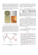
6. Radiation PatternThe radiation pattern of microstrip or patch antenna is broad. It has low radiation power and narrow frequency bandwidth.The radiation pattern of a microstrip or patch antenna is shown above. It has lesser directivity. To have a greater directivity, an array can be formed by using these patch antennas.
7. AdvantagesThe following are the advantages of Micro strip antenna − Small SizeLightweightLow costEase of installationDisadvantagesThe following are the disadvantages of Micro strip antenna −Inefficient radiationNarrow frequency bandwidth
8. ApplicationsThe following are the applications of Micro strip antenna −Used in Space craft applicationsUsed in Air craft applicationsUsed in Low profile antenna applications The bandwidth can be increased By increasing the thickness h of the parallel plate transmission line.By use of high dielectric constant ε substrate so that the physical dimensions of the parallel plate line are decreased.By increasing the inductance of the micrpstrip by cutting holes or slot in it.By adding the reactive component to reduce the VSWR.In order to increase the directivity of the antenna, multiple microstrip radiators are used in cascade to form an array.
9. Horn Antenna
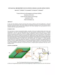
10. Antenna Theory - HornTo improve the radiation efficiency and directivity of the beam, the wave guide should be provided with an extended aperture to make the abrupt discontinuity of the wave into a gradual transformation. So that all the energy in the forward direction gets radiated. This can be termed as Flaring. Now, this can be done using a horn antenna.Frequency RangeThe operational frequency range of a horn antenna is around 300MHz to 30GHz. This antenna works in UHF and SHF frequency ranges.Construction & Working of Horn AntennaThe energy of the beam when slowly transform into radiation, the losses are reduced and the focusing of the beam improves. A Horn antenna may be considered as a flared out wave guide, by which the directivity is improved and the diffraction is reduced.
11. The above image shows the model of a horn antenna. The flaring of the horn is clearly shown. There are several horn configurations out of which, three configurations are most commonly used.
12. Sectoral hornThis type of horn antenna, flares out in only one direction. Flaring in the direction of Electric vector produces the sectorial E-plane horn. Similarly, flaring in the direction of Magnetic vector, produces the sectorial H-plane horn.Pyramidal hornThis type of horn antenna has flaring on both sides. If flaring is done on both the E & H walls of a rectangular waveguide, then pyramidal horn antenna is produced. This antenna has the shape of a truncated pyramid.Conical hornWhen the walls of a circular wave guide are flared, it is known as a conical horn. This is a logical termination of a circular wave guide.
13. The above figures show the types of horn configurations, which were discussed earlier.Flaring helps to match the antenna impedance with the free space impedance for better radiation. It avoids standing wave ratio and provides greater directivity and narrower beam width. The flared wave guide can be technically termed as Electromagnetic Horn Radiator.
14. Flare angle, Φ of the horn antenna is an important factor to be considered. If this is too small, then the resulting wave will be spherical instead of plane and the radiated beam will not be directive. Hence, the flare angle should have an optimum value and is closely related to its length.CombinationsHorn antennas, may also be combined with parabolic reflector antennas to form special type of horn antennas. These are −Cass-horn antennaHog-horn or triply folded horn reflectorIn Cass-horn antenna, radio waves are collected by the large bottom surface, which is parabolically curved and reflected upward at 45° angle. After hitting top surface, they are reflected to the focal point. The gain and beam width of these are just like parabolic reflectors.
15. In hog-horn antenna, a parabolic cylinder is joined to pyramidal horn, where the beam reaches apex of the horn. It forms a low-noise microwave antenna. The main advantage of hog-horn antenna is that its receiving point does not move, though the antenna is rotated about its axis.Radiation PatternThe radiation pattern of a horn antenna is a Spherical Wave front. The following figure shows the radiation pattern of horn antenna. The wave radiates from the aperture, minimizing the diffraction of waves. The flaring keeps the beam focussed. The radiated beam has high directivity.
16.
17. AdvantagesThe following are the advantages of Horn antenna −Small minor lobes are formedImpedance matching is goodGreater directivityNarrower beam widthStanding waves are avoidedDisadvantagesThe following are the disadvantages of Horn antenna −Designing of flare angle, decides the directivityFlare angle and length of the flare should not be very smallApplicationsThe following are the applications of Horn antenna −Used for astronomical studiesUsed in microwave applications
18.
19.
20. θLLδh/2
21. ReferencesAntenna Theory by Constantine A BalaniAntenna & Wave Propagation by K D PrasadAntenna Theory (Tutorials Point) https://www.tutorialspoint.com/antenna_theory/antenna_theory_broad_side_array.htm
22.