/
02 Route Location Reference 02 Route Location Reference

02 Route Location Reference - PowerPoint Presentation

brianna
brianna . @brianna
Follow
65 views
Uploaded On 2023-10-27

02 Route Location Reference - PPT Presentation

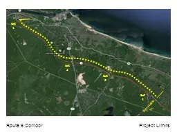
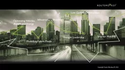
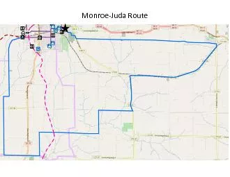
JG Schoon GEOMETRIC DESIGN PROJECTS FOR HIGHWAYS Second Edition Factors Affecting Selection of the Highway Route EXAMINATION OF NATURAL AND MANMADE FEATURES Selection of a possible route for a proposed highway is ID: 1025235

route design costs highway design route highway costs features topographic maps photographs selection construction information cost project aerial environmental

Share:

Link:

Embed:

Download Presentation from below link

Download Presentation The PPT/PDF document "02 Route Location Reference" is the property of its rightful owner. Permission is granted to download and print the materials on this web site for personal, non-commercial use only, and to display it on your personal computer provided you do not modify the materials and that you retain all copyright notices contained in the materials. By downloading content from our website, you accept the terms of this agreement.


Presentation Transcript

1. 02Route LocationReference:J.G. Schoon, GEOMETRIC DESIGN PROJECTS FOR HIGHWAYS, Second Edition

2. Factors Affecting Selection of the HighwayRouteEXAMINATION OF NATURAL AND MAN-MADE FEATURESSelection of a possible route for a proposed highway is determined largely by relating topographic features, human habitation, and environmental features of the area under consideration to geometric design controls.Therefore, before starting the route selection process, a review of the area's major topographic and other features likely to affect the route selection is needed. Several sources of information are available to assist the review. They include:

3. 1. Topographic Maps. Usually the maps of the United States Geological Survey (USGS)at a scale of 1:25,000 and a contour interval of 3 m provide the minimum required detailfor preliminary route selection. Larger scale maps may also be used if available.2. Aerial Photographs. The two main types of aerial photographs employed in routedesign are stereographic and oblique. Stereographic photographs, usually at the samescale as the topographic maps, may assist in determining important geological, ecological,and cultural information. Also, with the assistance of appropriate measuring devices, theyform the basis for automated route selection and design, including the use of computeraided methods. Oblique aerial photographs may be used to supplement the stereophotographs.3. Geological and Soil Maps. These are available through the USGS, the U.S. SoilConservation Service, or through state agencies, and may provide useful information,particularly concerning pavement design, although more detailed information is usuallynecessary for preliminary design.4. Ground Surveys. Reconnaissance or more detailed surveys should be made of thearea, especially if the terrain is rugged or if additional details are required. As early aspossible in the process, the design engineer should "walk the route," but practicalities maypreclude this procedure early in the project.The items used and the major steps in the review may typically include the following:

4. Topographic Maps ~ Examine the terrain in general between the start and endpoints of the proposed route and make note of the following information, usually availablefrom a topographic and geological maps. Typical kinds of information shown on mosttopographic maps are illustrated in the Appendices. An inspection of the maps shouldinclude the following steps:1. Identify unsuitable ground conditions such as wetlands, rock outcrops, areas subject toflash floods or avalanche, and other features of an obviously difficult terrain forhighway construction.2. Examine the contour lines to obtain an initial estimate of the gradients that exist onundulating or mountainous parts of the potential route. The steepness of the terrainmay be approximately determined by observing the number of contour lines and theirvertical interval along a horizontal distance located at right angles to them. Slopessteeper than, say, approximately 10%, may be delineated on the map.3. Define streams, rivers, ravines, or other topographic features that indicate the possibleneed for bridges or other extensive ancillary works to the highway itself.4. List typical types of subsurface and soil conditions that may be expected, as indicatedby the topographic features found on the topographic and geological map.5. Summarize the findings of the examination of the above items on maps or overlays inorder to guide the next steps in the route selection. Items 1 through 4 are describedgraphically in Figures 1-1 through 1-3 where, as an example, the route of a highwayconnecting points A and B is being considered.

5.

6.

7.

8. Aerial Photography ~ The next step is to examine available aerial and other photography, when available, to confirm or modify the information on the map. The following procedure is usually appropriate: Examine the stereoscopic aerial photographs to determine whether topographic andcultural features are different from those shown on the map. Document any changes on anoverlay so this may be recorded on the map. The type of features found might includehuman activity, swamp or marsh areas that no longer exist, or areas that may be sensitivedue to presence of wildlife or other ecological factors. In addition, conditions potentiallyhazardous to a highway such as avalanches, mudslides, or flooding may be evident. Aerialphotography can provide excellent indications of anticipated ground conditions. Examplesof the stereoscopic photographs are presented in Figure 1-4.Examine the oblique photographs to obtain a sense of the developmental and estheticfeatures of the area and a general idea of the grades and other topographic characteristics.These, of course, should be cross-checked with those on the map to ensurecorrespondence. Figure 1-5 provides several oblique photographs of the project area.Note in particular the presence of trees that may make identification of the groundsurface features difficult on the aerial photographs.In addition to the above considerations, make note of local features which may beenvironmentally sensitive to the presence of a proposed highway. Guidelines foridentifying these features and mitigating the effects of potential highways on theenvironment are described in several documents listed in the bibliography.

9. FIGURE 1-4EXAMPLES OF STEREOGRAPHICAERIAL PHOTOGRAPHSFIGURE 1-5EXAMPLES OF OBLIQUEAERIAL PHOTOGRAPHS

10. IDENTIFICATION OF TECHNICALLY FEASIBLE ROUTESThe guiding principle in designing a possible route is to improve the transportationbetween specified points. Within the economic and social framework that typicallyapplies, the term "improve" may be broadly interpreted as "to make less expensive andsafer for the public in general as well as for the highway's users, while at the same timemaintaining or contributing to the improvement of environmental quality." Furthermore,the route should be "technically feasible" in that no excessive construction or maintenanceproblems are envisaged, and such that the design controls and policy on geometric designof the highway agency having jurisdiction are adhered to. In this book, the policies of theAmerican Association of State Highway and Transportation Officials (AASHTO) aregenerally used.A highway improvement may be an upgraded existing highway or a completely newroute and should always be considered as a component of the overall transportationsystem.

11. OBJECTIVES IN IDENTIFYING ACCEPTABLE ROUTESIn defining a broadly acceptable route, therefore, the approach typically involvescompromising between the user costs and construction costs while seeking the route andphysical conditions that result in the least adverse environmental impact.How is a balance struck between user costs and construction costs? A rather extremeexample may be used to illustrate this problem: suppose the objective is to define a routebetween two points on existing highways separated by mountainous terrain. The least costroute for vehicle users on a "per vehicle kilometer" basis would clearly be a horizontal andvertical alignment permitting a high design speed (long sight distances, large radiuscurves, etc.) route with bridges and tunnels and extensive cuts and fills to overcome therugged terrain. At the other extreme, a winding road following the contours of the terrain,with little or no cut and fill sections, few bridges, and no tunnels, would result in higheruser costs due to sharp curves, resultant reductions in speed, and greater likelihood ofaccidents. However, such a road would undoubtedly cost less to build, even if it weresomewhat longer than the first, because of the reduced amount of expensive excavationand filling and construction of bridges and tunnels.In a more formalized way, as developed by the World Bank, the Highway Designand Maintenance Model states that (in selecting a particular highway) " .. .the basic task isto predict total life-cycle costs - construction, maintenance, and road user costs - as afunction of the road design, maintenance standards and other policy options which may be considered", and adds that a broader definition of societal costs would include suchexamples as air pollution as it affects non-road-users.

12. For any given volume of traffic, the relationship between the user cost, constructioncost, and total cost can be shown conceptually, as in Figure 1-6. The lower the designstandards, the lower the construction costs (because of the reduced need for cut, fill,bridges, and tunnels). Conversely, the travel cost to users increases due to the reducedspeed and increased travel time, and the increased likelihood of accidents due to the lowergeometric design standards. Examples of higher and lower geometric design standardsapplied to highways are shown in Figure 1-7. It must be emphasized that both of thesehighways satisfy specified criteria in terms of their function and role within the overallsystem, and the terms "higher" and "lower" should not be construed as meaning "better"and "worse" designs.The preferred route can only be determined by comparing the total costs for usersand the construction and maintenance costs incurred by the implementing agency, for eachtechnically feasible alternative, and selecting that alternative with the least monetary costand acceptable non-quantifiable impacts.The economic analysis involved in this process is described in several publications.See the bibliography for these. In the examples provided in this book, however, we areconcerned primarily with establishing the technical feasibility of each alternative, and itscapital cost. In the worked example in Chapter 4 we also include approximatemaintenance costs and approximate vehicle operating cost as an aid to indicating therelative merits of the alternatives.

13. FIGURE 1-6COST AND DESIGN LEVELRELATIONSHIPSFIGURE 1-7EXAMPLES OF HIGHWAYS BUILT TODIFFERENT DESIGN STANDARDS

14. ROUTE SELECTION AND THE DESIGN PROCESSPreliminary Design Related to Total Design Process -As indicated inthe Preface, the material discussed in this book involves only a part of the full highwaydesign process, and each organization will have its own guidelines and procedures to beadhered to.An example process is that for a state highway design in Massachusetts, as shown inTable 1-1. A total of 55 steps are required; Nos. 16 through 22 typify the activities of thehighway designer as described in this book. The next step, No. 23, enables the 25%project review to be conducted. In this step the preliminary design and cost estimates arereviewed by federal and state officials. This ensures that any problems in the project canbe adequately identified and addressed and that the project is sufficiently advanced toproceed with public hearings and the subsequent permitting, detailed design, and approvalprocess.

15. Environmental Reporting Requirements -- The level of detail of thepreliminary route selection and design is also consistent with Class III actions inaccordance with the Federal Highway Administrations1 level of documentation asdescribed in the appropriate code of Federal Regulations, Title 23 Part 771. A Class IIIaction is an action in which the significance of the impact is not clearly established. Theseactions require the preparation of an Environmental Assessment describing theenvironmental impacts of the proposed works and its alternatives. This assessment assistsin deciding the nature of further environmental analysis and needed documentation. If theFederal Highway Administration determines that a proposed project will not have asignificant impact on the environment, a statement to that effect may be prepared. Thelevel of detail of the project described in this book would in many respects be appropriatefor guiding the preparation of such an environmental assessment document.