
Flow chart of combed yarn Mixing and blending of cotton fiber in blow room Mixing If different grade of same fibers are kept together then it is called mixing Types of Mixing 1 volume mixing ID: 1018994
Download Presentation The PPT/PDF document "Flow chart of carded yarn:" is the property of its rightful owner. Permission is granted to download and print the materials on this web site for personal, non-commercial use only, and to display it on your personal computer provided you do not modify the materials and that you retain all copyright notices contained in the materials. By downloading content from our website, you accept the terms of this agreement.


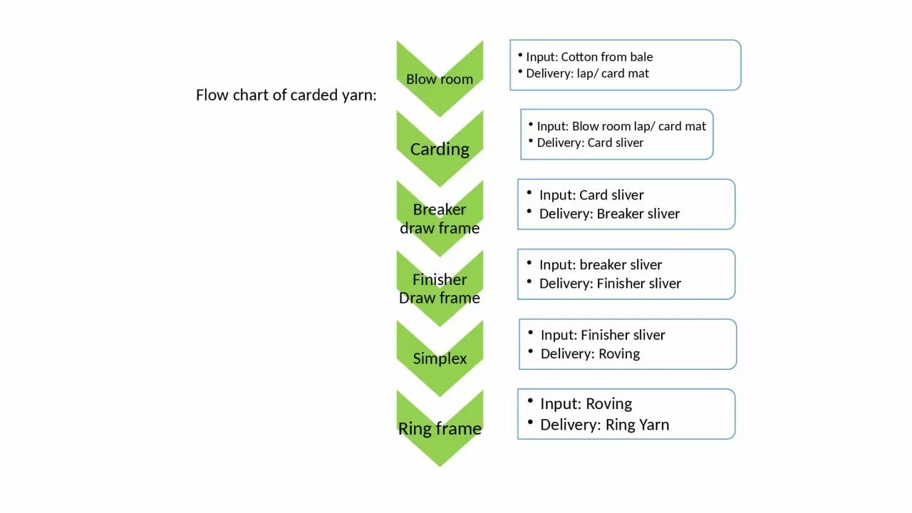
1. Flow chart of carded yarn:
2. Flow chart of combed yarn:
3. Mixing and blending of cotton fiber in blow roomMixing:If different grade of same fibers are kept together, then it is called mixing.Types of Mixing:1. volume mixing2. weight mixing3. hand stock mixing4. bin mixing5. mixing by hopper6. lap mixing7. card mixing8. sliver mixingBlending:When different fibers of same or different grades are kept together, then it is called blending.Types of Blending:1. hand stock blending2. bin blending3. lap blending4. card blending5. draw frame blending
4. BLOW ROOM
5. Blow room: Cotton fibre is compressed in a bale of 200 to 250 kg. This highly compressed cotton firbe need to be open at first as a part of yarn manufacturing. And there are 1.5% to 7% trash in cotton bale which is also needed to be removed before further processing. This process of opening & cleaning is knows as blow room process. Blow room consists of a number of m/c used in succession to open & clean the cotton fibre to the required degree. 40% to 70% of total trash is removed in this section.Number of opening machines Type of beater Type of beating Beater speed Setting between feed roller and beater Production rate of individual machine Production rate of the entire line Thickness of the feed web Density of the feed web Fibre micronaire Size of the flocks in the feed Type of clothing of the beater Point density of clothing Type of grid and grid settings Air flow through the grid Position of the machine in the sequence Amount of trash in the material Type of trash in the material Temp and relative humidity in the blow room department Process parameter in the blow room:
6. Objects of blow room process:To open the compressed layer of bale of cotton or any staple fibres with minimum damage to the fibres.To remove the impurities like sand, seed, bits, neps & short fibres present in the cotton with minimum loss of lint by opening & blending.To effect a through blending with minimum neps formation.To convert the mass of cotton fibres into a uniform thick sheet of cotton both longitudinally & transversely & fed as it in the case of chute feed system or wound in the form of a compactly built lap with minimum lap rejection.Intensive de-dusting of cotton fibres to extract micro- dust in order to improve the working of opened spinning m/c.Fibre recovery from the waste produced by the various processes during the conversion of fibre to yarn in order to reduce the consumption of raw material.
7. Technological performance of a blow room line and influencing factors
8. Opening: The first operation required in the blowroom line is opening. Tuft weight can be reduced to about 0,1 mg in the blowroom. The figure indicate that the degree of opening changes along a blowroom line. This line is a theoretical layout for study purposes only. The flattening of the curve toward the end shows that the line is far too long. It should end somewhere at machine No. 3 or (at least) No. 4. The small improvements by each of the subsequent machines are obtained only by considerable additional effort, stressing of the material, unnecessary fiber loss and a striking increase in neppiness. Openness of the fiber material after the various blowroom machine stages; axis A: Degree of opening (specific volume); axis B: Blowroom stagesBasic operation in blow room:
9. Cleaning: A blowroom installation removes approximately 40 - 70% of the impurities. The result is dependent on the raw material, the machines and the environmental conditions. The diagram by illustrates the dependence of cleaning on raw material type, in this case on the level of impurities.Figure: Degree of cleaning (A) as a function of the trash content (B) of the raw material in % The cleaning effect is a matter of adjustment. It is shown in bottom figure that, increasing the degree of cleaning also increases the negative effect on cotton when trying to improve cleaning by intensifying the operation, and this occurs mostly exponentially. Therefore each machine in the line has an optimum range of treatment. It is essential to know this range and to operate within it. Figure: Operational efficiency and side effects Normally, fibers represent about 40 - 60% of blowroom waste. Since the proportion of fibers in waste differs from one machine to another, and can be strongly influenced, the fiber loss at each machine should be known. It can be expressed as a percentage of good fiber loss in relation to total material eliminated, i.e. in cleaning efficiency (CE): AT = total waste (%); AF = good fibers eliminated (%). For example, if AT = 2.1% and AF = 0.65%:
10. Almost all manufacturers of blowroom machinery now offer dust-removing machines or equipment in addition to opening and cleaning machines. Dust removal is not an easy operation, since the dust particles are completely enclosed within the flocks and hence are held back during suction. It is mainly the suction units that remove dust (in this example 64%), dust removal will be more intensive the smaller the tufts. It follows that dust elimination takes place at all stages of the spinning process as shown in figure.Dust Removal:Fig. 5 – Dust removal as a percentage of the dust content of the raw cotton (A) at the various processing stages (B): 1 - 5, blowroom machines; 6, card; 7, draw frames; (a) filter deposit; (b) licker-in deposit; I, dust in the waste; II, dust in the exhaust air.
11. Blending:intensive blending in a suitable blending machine must be carried out after separate tuft extraction from individual bales of the layout. This blending operation must collect the bunches of fibers arriving sequentially from individual bales and mix them thoroughly. Multi mixer is the machine of blow room where the uniform blending is carried out. Figure – Sandwich blending of raw material componentsIn conventional machineries, lap blending was the most significant one. doubling scutcher is required in this case; this has a conveyor lattice on which four to six laps (L) could be laid and jointly rolled-off. Lap blending produces very good transverse blends and also a good longitudinal blend, Figure – Lap blending on an old scutcher
12. Even feed of material of the card: Finally the blow room must ensure that raw material is evenly delivered to the cards. Previously, this was carried out by means of precisely weighed laps from the scutcher, but automatic flock feeding installations are increasingly being used. While in the introductory phase such installations were subject to problem regarding evenness of flock deliver, today they generally operate well or at least adequately.
13. Introduction of blow room line:Figure – Rieter blowroom line; 1. Bale opener UNIfloc A11; 2. Pre-cleaner UNIclean B 12; 3. Homogenous mixer UNImix B 75; 4. Storage and feeding machine UNIstore A 78; 5. Condenser A 21; 6. Card C 60; 7. Sliver Coiler CBA 4
14. Components of the blow room machine:Feeding Apparatus:Feed to a beater with two clamping rollers Feed with an upper roller and a bottom table Feed with a roller and pedals Operating with two clamping cylinders gives the best forward motion, but unfortunately also the greatest clamping distance (a) between the cylinders and the beating elements. In a device with a feed roller and table the clamping distance (a) can be very small. This results in intensive opening. Where pedals are used (Fig. 12), the table is divided into many sections, each of which individually presses the web against the roller, e.g. via spring pressure. This provides secure clamping with a small clamping distance (a).
15. Opening devices:Opening units can be classified as: endless pathgripping devices rotating assemblies Depending on their design, construction, adjustment, etc., these assemblies exert enormous influence on the whole process.1. End less path device:Spiked lattices is known as endless path device. It serves as forwarding and opening devices in bale openers and hopper feeders. They consist of circulating, endless lattices or belts with transverse bars at short intervals. The bars are of wood or aluminum; steel spikes are set into the bars at an angle and at greater or lesser spacing. The intensity of the opening action is dependent upon:the distance between the devices; the speed ratios; the total working surface;the number of points.
16. 2. Gripping elements (plucking spring):Some manufacturers, for example former Schubert & Salzer and Trützschler, have used plucking springs for opening. Two spring systems, facing each other like the jaws of a pair of tongs, are parted and dropped into the feed material and are then closed before being lifted clear. They grasp the material like fingers. This type of gripping is the most gentle of all methods of opening, but it produces mostly large to very large clumps of uneven size. This type of opening device is therefore no longer used.
17. 3. Rotating Devices (Roller with teeth, blades or spikes):Flat, oval or round bars are welded, riveted or screwed to closed cylinders. The rollers are therefore called spiked rollers. Various spacing of the striker elements are used. These devices are incorporated mainly in modern horizontal cleaners, chute feeds, mixing bale openers, step cleaners, etc., which are located from the start to the middle of the blowroom line. At the start of the line, the spacing of the striker elements on the roller is greater; finer spacing are used in the middle (to the end) of the line. The rollers rotate at speeds in the range of 600 - 1 000 rpm.