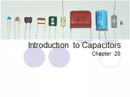
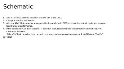
By Vishnu Engineer RD A capacitor is a passive electronic component It forms the basic building block of an electronic circuit Without capacitor electronic circuits cannot be designed I ID: 833327
Download Pdf The PPT/PDF document "DEKI CAPACITOR SOLUTIONS" is the property of its rightful owner. Permission is granted to download and print the materials on this web site for personal, non-commercial use only, and to display it on your personal computer provided you do not modify the materials and that you retain all copyright notices contained in the materials. By downloading content from our website, you accept the terms of this agreement.
DEKI CAPACITOR SOLUTIONSByVishnu â
DEKI CAPACITOR SOLUTIONSByVishnu âEngineer R&DA capacitoris a passive electronic component. It forms the basic building block of an electronic circuit. Without capacitor electronic circuits cannot be designedïIt is a device for storing electric charge.ïconsisting of
a pair of conductorsseparated by a d
a pair of conductorsseparated by a dielectric.ïfor blocking direct currentwhile allowing alternating currentto passïC = Q/V Farads2CAPACITORâ¦DEKI ELECTRONICS LTD3CAPACITORâ¦DEKI ELECTRONICS LTDCONSTRUCTIONSYMBOLTheory of Operationï¯When the supply is
given to the conducting plates.ï¯Th
given to the conducting plates.ï¯The dielectric between the conducting plates will polarize and arrange themselves in a regular fashion.ï¯An electron flow occurs from negatively charged plate to the positively charged plate due to polarizationï¯Thus current flow from
positively charged plate to the negativ
positively charged plate to the negative plateï¯The energy stored in the capacitor is given by E=CV2/24DEKI ELECTRONICS LTDParametersA capacitor has four important parameters. ïRated Capacitance ïRated VoltageïInsulation ResistanceïIt is the measure of r
esistivity in dc. Under a stationary dc
esistivity in dc. Under a stationary dc voltage, a leakage current flows through the dielectric and over the capacitance surfaces.ïRins =V (applied voltage)/I (Leakage current)ïLoss Factor or dissipation Factor(Tanδ)5DEKI ELECTRONICS LTD6ï¯With a perfect dielectric ca
pacitor, current will lead the applied v
pacitor, current will lead the applied voltage by 90º. When dealing with less than perfect dielectric materials, current in a capacitor will lead the applied voltage by less than 90°. This can be visualized in the current-voltage phase relation of a dielectric visualized inThe
loss angle is usually expressed as the
loss angle is usually expressed as the tangent of delta, or just tan delta(dissipation factor)Dissipation Factorâ¦DEKI ELECTRONICS LTD7The ESR is the resistive part of the equivalent series circuit and is temperature and frequency dependent. The ESR can be calculated from the
dissipation factor (tan δ) as follows
dissipation factor (tan δ) as follows:ESR = tan δ / ÏCThe power dissipated by a capacitor is a function of the voltage across or the current (I) through the equivalent series resistance ESR.P = w ×C ×tan δ ×U2P = 2 ×Ï ×f ×C ×tan δ ×U2where f = frequenc
y, tan δ = maximum value specified, U
y, tan δ = maximum value specified, U =rated voltageESR & Power dissipationâ¦DEKI ELECTRONICS LTDTypes of capacitorsDepending upon the dielectric used, there are several types of capacitorsï¯Ceramic Capacitorsï¯Paper capacitorsï¯Glass capacitorsï¯Electrolytic capac
itorsï¯Film capacitorsï®Polyester
itorsï¯Film capacitorsï®Polyester film dielectricï®Polypropylene film dielectricï®Polyethylene Naphthalate dielectricï®Polyphenylene sulphide dielectric9INDUCTIVE (MYLAR)NON-INDUCTIVE1 ) PP (POLYPROPYLENE)2) PET (POLYESTER)3) PEP (POLYPROPYLENE + POLYESTER)4)
PES5) PSH1 )MPP2) MPET3) PP-NI,PE
PES5) PSH1 )MPP2) MPET3) PP-NI,PET-NI4) PP-MPPDEKI ELECTRONICS LTDDEKI Film CAPACITORSâ¦10INDUCTIVE (MYLAR)ïHigh Dv/dt ïHigh IRïGood Current carrying capability.ïBetter capacitance stabilityDEKI ELECTRONICS LTD11NON-INDUCTIVEFor voltage 250 VAC
For voltage 500 VACFor voltage 750 V
For voltage 500 VACFor voltage 750 VACDEKI ELECTRONICS LTDïSmaller size.ïHigh ReliabilityïSelf Healing12Self Healingâ¦ï¯For capacitors made with metalized film, self-healing or "clearing" removes a fault or short circuit in the dielectric film by vaporizin
g the metallization near the defectï¯
g the metallization near the defectï¯The vaporized metal oxidizes over time, aiding in the isolation of a fault area. ï¯The self-healing feature of the metallized capacitor offers a distinct advantage over the non-metallized unit. DEKI ELECTRONICS LTDIf the maximum op
erating temperatureï105oC -PP
erating temperatureï105oC -PP filmï120oC -PET filmï150oC -PEN filmï150oC -PPS film (upto to 170oC)For PP film, â¢Tanδ<0.0008 at 1 kHz,â¢Tanδ<0.001 at 10 kHz,â¢Tanδ<0.003 at 100 kHz.ïIn cost, PPSPENPP&
#x0000;PET film13Selection of filmsDE
#x0000;PET film13Selection of filmsDEKI ELECTRONICS LTDFor PET film,â¢Tanδ0.008 at 1 kHz,â¢Tanδ0.015 at 10 kHz,â¢Tanδ0.030 at 100 kHz.Properties of Films14For PET film:For PP film:Dielectric constant Vs TemperatureDEKI ELECTRONICS LTDC = εoεrA/D15Pro
perties of FilmsFor PP film:For PET fi
perties of FilmsFor PP film:For PET film:Tanδ Vs TemperatureDEKI ELECTRONICS LTDESR = tan δ / 2fC16Properties of FilmsInsulation resistance Vs TemperatureFor PET film:For PP film:DEKI ELECTRONICS LTD17Comparison of filmsDEKI ELECTRONICS LTDïDC ApplicationVr
0000; DC voltage of the signalIR shoul
0000; DC voltage of the signalIR should be very highïAC Applicationtanδ is very importantself-heating ïPulse Applicationhigh current/voltage pulses at short durationsself-heating 18DEKI ELECTRONICS LTDSelection by applicationWHY POLYPROPYLENE CAPACITOR FOR SWITC
HING ïPolypropylenecapacitoriside
HING ïPolypropylenecapacitorisidealchoiceforhighfrequencyapplicationsbecauseofitslowlossfactor.Forstriking,thecapacitorshouldhavehighdv/dtratingandlowlossfactor.LowlossfactorispreferredbecauseïP=2..f.C.tanδ.VRMS2--------(1)
ïâT=P.RTHC--------(2)ï
ïâT=P.RTHC--------(2)ïP=powerdissipationincapacitor.âT=TemperatureRiseïRTH=ThermalresistanceofthecapacitorïFromaboveeq.wecantellpowerdissipationisdirectlyproportionaltothefrequency,lossfactorandVRMS.Heatgeneratedin
thecapacitorisproportionaltothepow
thecapacitorisproportionaltothepowerdissipation.Buttemperatureriseisnotallowedmorethan10Catitscategorytemperature.Forpolypropylenecapacitorslossfactorislowathighfrequency.sothetemperatureriseconsiderablelessthanothercapacitor.1920DEKI ELE
CTRONICS LTDCFLâ¦21RFI SUPPRESSION-
CTRONICS LTDCFLâ¦21RFI SUPPRESSION-(C1)Cap Value : 68nf to 220nfïX2-Series â275 VACïMPET â( 400 â630 Vdc)START UP-(C2)Cap Value :10nf to 100nf(63 â100Vdc) ïPET Film foil inductive typeïMPET For C 0.082 MfdCFLâ¦( RFI Suppression a
nd Startup)DEKI ELECTRONICS LTD22CFLâ
nd Startup)DEKI ELECTRONICS LTD22CFLâ¦( Snubber & Blocking)SNUBBER-(C3)0.68nf to 0.0033μf(630-1000Vdc)ïPP Film foil inductive ïPEP film foil inductive BLOCKING-(C4)Recommended Capacitor is ïPET ( Film/Foil) .ïMPET ( Box &Dip) Cap Value : 0.022 â
0.068μfRated Voltage : 250 â400Vd
0.068μfRated Voltage : 250 â400VdcDEKI ELECTRONICS LTD23STRIKING-( C5)cap 0.0022μF to 0.0068 μf.ïPP inductive typeïPET inductive type ïPEP film foil inductiveïDPSHïMPP-MPPCFLâ¦( Striking)DEKI ELECTRONICS LTD24H.F Ballastâ¦Capacitance value(R
FI Filter) : ï0.0047 Mfd to 2.2 Mfd
FI Filter) : ï0.0047 Mfd to 2.2 Mfd (for C1-X2 Class (275VAC/305Vac)ï0.001Mfd to 0.1 Mfd (for C2,C3-250 ~275VAC)For smoothening the wave form after PFC correction Deki has MPET as well as MPP series .Range starts from 10 nf to 10 Mfd . Voltage range is from 420
VDC to 630 VDC. DEKI ELECTRONICS LTDR
VDC to 630 VDC. DEKI ELECTRONICS LTDRFI FilterP.F.C25H.F Ballastâ¦(Striking)Deki Range â¦AC & Pulse capacitor seriesa) MPP/MPP AC-seriesb) PP/MPP seriesc) MMPP seriesDEKI ELECTRONICS LTD26Selection of capacitor for strikingFollowing condition should be satisfied wh
en selecting capacitor for striking app
en selecting capacitor for striking application.ïVP Should be less than D.C Rated voltage.ïVP-P should be less than 2x1.414x VRMS.ïdv/dt rating should be fulfilledïPeak current should be less than C(dv/dt)ïTemperature rise should be less than 10ËC at its cate
gory temperature.DEKI ELECTRONICS LTD
gory temperature.DEKI ELECTRONICS LTDCapacitors for Energy metersï¯A capacitive power supply is the best solution for a low-cost energy meter. It works on the principle of reducing the line voltage (Voltage dropper) by having a series capacitor between phase and neutral. Cu
rrent flowing through this capacitor is
rrent flowing through this capacitor is inversely proportional to the impedance of the capacitor as given by the formula:Impedance (Z) = 1/(2ÏfC)ï¯f is the line frequency andï¯C is the capacitance of the series impedance capacitor.DEKI ELECTRONICS LTDCapacitanceFunctionT
ypeVoltage RangeCapacitance rangeC1N
ypeVoltage RangeCapacitance rangeC1Noise filterMPP-X2275Vac/305Vac0.01 to 1μFC2Ripple filterElectrolytic--C3 (Series impedance capacitor)Voltage DropperMPP-AC, MPP-X2, MPET-AC-High capacitance stability275Vac/305Vac, 325Vac, 440Vac0.1 to 1μFDEKI E