
0x003 011 Modified and presented by Mohamed Zaki Topics Simple Computer Architecture Main Components CPU Architecture Storage amp Memory Devices Screen amp Display Bus Systems Input Output Architecture ID: 732724
Download Presentation The PPT/PDF document "Hardware Components 1 Lesson 3" is the property of its rightful owner. Permission is granted to download and print the materials on this web site for personal, non-commercial use only, and to display it on your personal computer provided you do not modify the materials and that you retain all copyright notices contained in the materials. By downloading content from our website, you accept the terms of this agreement.


Slide1
Hardware Components
1
Lesson 3 0x003011
Modified and presented by : Mohamed Zaki Slide2
Topics
Simple Computer ArchitectureMain Components CPU ArchitectureStorage & Memory DevicesScreen & Display
Bus SystemsInput / Output ArchitectureExecuting instructionInstruction set types2Slide3
COMPUTER ARCHITECTURE Von Neumann Architecture
CPU/
ProcessorMain MemoryAddress Bus
Data Bus
Control Bus
Input
& Output Devices Slide4
Examples of CPUs
Based on the manufacturer:Intel:
CeleronPentium I.Pentium MMX. ( Multimedia Extension)Pentium II. Pentium III. & Pentium 4.Centrino. ( Mobile Technology)Core 2 DUODual core/ Quad core/ Eight core Core i series (Laptop, Desktop, and Mobile Device Processors)Xeon (
Server and Workstation Processors)AMD.
ARMDual Core A4,A5, A6
ARM Cortex-A9 MPCore
(for iPad & iPhone and others)
4Slide5
CPU Architecture
CPU:
Is the part of a computer in which arithmetic and logical operations are performed and instructions are decoded then executed.CPU Components:ALU ( Arithmetic and Logic Unit) Is the unit where all Arithmetic and Logic operation are performed CU (Control Unit)Is the unit which controls communication and co-ordination between input/output and other devices.Registers:Are high speed & small in size temporary memory storage areas used during data manipulation ( calculation , comparison , etc..)The clock:It is a circuit for generating pulses that enable computer components to work in an ordered manner .
5
CPU : Central Processing Unit. Also called
ProcessorSlide6
Memory DevicesAny memory is constructed from a collection of memory cells.
The size of the memory is measured by Bytes (8 cells)Each memory cell is made of Transistors and/or Capacitors connected together.
Each cell contains a combination of binary data(0s or 1s).Types of Memory:RAM. Is used as Main Memory of the ComputerROM. (Helps to store data permanently such as Setup-data) Cache Memory ( Helps during program execution )6Slide7
Random Access Memory (RAM)
It also called Main or Primary Memory.Random means: At any time you can access any where
Access means: Read or Write data Programs & Data are stored there before processing .The larger amount of RAM, the quicker programs will run.More than one type of RAMs are used in modern PCs, like DRAM(Dynamic RAM) and SDRAM(Synchronous DRAM)DDR SDRAM / DDR2 SDRAMDDR3 SDRAM / DDR4 SDRAMThe data will be lost if the power is cut (Volatile Memory).
7
Random Access
Sequential AccessSlide8
Random Access Memory (RAM)
8
memory modules for desktop PCs (DIMM).DDRDDR 2
DDR 3Slide9
Read Only Memory (ROM)
It holds the firmware program (BIOS) Basic Input/Output System. A set of initial instructions for input and output
Reading character from the keyboardDisplay character on the screen It starts the POST “ Power On Self Test” programIt contains auto-startup program that will load the necessary OS programs in RAM. The information remains in the ROM when the computer turned off. ( Nonvolatile Memory)
9Slide10
The Differences between ROM and RAM:
10
ROM (Read Only Memory)RAM (Random Access Memory)
Used to
store the BIOS
by the factory.
Mainly, ROM
can be used for read only,
but we can
write or modify
the ROM
under some conditions
.
Not volatile memory (i.e. the information remains in the ROM when the computer turned off)
Used to store programs such as accounting program, games, word processor by the user.
We can use the RAM for read and write data.
Volatile memory (i.e. the information in the RAM is removed when the power turned off)Slide11
Cache Memory
Is a small memory, located close to the processor?Some processors are built with internal cache memory.
It has much shorter access time than the RAM. Therefore, it is used to hold instructions and data that has recently been accessed or expected.There are two types of cache memory: L1 and L2.L1 ( Level 1) internal cache, built in with in the CPU.L2 ( Level 2) external cache, built in with in the Motherboard, L2 is lager than L1. ( A+ Book p 131)11Slide12
CPU, RAM, and Cache Diagram
12
CPUCacheRAM
Write through cache.
Write back cache.Slide13
Hard Disk
13Slide14
Hard Disk
is a data storage device used for storing and retrieving digital information using rapidly rotating discs (platters) coated with magnetic material.A magnetic heads arranged on a moving arm to read and write data to the surfaces.Slide15
Sector
Track
Magnetic polarity determines the bit value (1,0)
Bit Value is 1
Bit Value is 0
Disk Organization
0 0 1 0 1 1 1 0
The
Format
Command
is used to create Tracks and SectorsSlide16
Other Storage Devices
Flash Memory SSDDVD Disks Magnetic Tapes
Magnetic Tapes
DVD Disks
Flash Memory
(SSD)Types
http://
en.wikipedia.org/wiki/Secure_Digital
Slide17
Storage Device Hierarchy
Registers
Cache
Main Memory(RAM)
Flash Memory
Hard Disks
Magnetic Tapes
Size
Bytes
M Bytes
G Bytes
G Bytes
G – T Bytes
T Bytes
Speed
1
nsec
10
nsec
100
nsec
msec
msec
sec -min
Hard Disk
and
Tapes
have mechanical movements
Others
do not have and called Solid Sate Devices (SSD)
Slide18
Bus Systems (Connecting them together )
Is a collection of parallel electrical lines which connect the computer components.The buses used to transfer:
Data signals.Address signals.Control signals.18Slide19
Bus Systems
The address bus is the set of wires carrying the addressing information used to describe the memory location, which the data is being sent or retrieved.The size of the address bus indicates the maximum amount of RAM that a chip can address.
Size of memory that can be addressed= 2LWere L = No. of Lines in address bus ( Size of address bus)19Address BusSlide20
Bus Systems
Size of address bus
Size of memorySize of address busSize of memory12116216 ~= 64 KB22
2 =4202
20 ~= 1 MB3
2
3
=8
30
2
20
=1 GB
4
2
4
=16
32
2
32
=4 GB
:
: : :
64
264=16 Exa Byte
10210 =1024=1KB
11211=2
10
x2
1
=2 KB
12
2
12
=2
10
x2
2
=4 KB
20
Address BusSlide21
Bus Systems
Examples:1) how many addresses can be built by 3 digits (3 lines):
2n = 23 = 8 address bus locations from ( 000 to 111 ) 2): how many addresses can be built by 3 digits (3 lines):2n = 23 = 8 address bus locations from ( 000 to 111 )21
Address BusSlide22
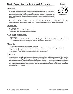
Input / Output Architecture
The computer has the ability to send and receive data to and from other devices.We can transfer data in parallel and serial lines.When the CPU wishes to send data to a particular I/O devices it places a unique identity code ( address ) onto the address line.
Only the device that recognizes that code will respond to the command that is placed on the control line.22Slide23
Screen
Screen is a display device that is typically a panel of lighting elements such
Liquid Crystal Display (LCD) or Light Emitting Diode (LED).The screen has a two-dimensional grid of what we call Picture elements (pixels) which is the smallest controllable element of a picture represented on the screen. pixels are often represented using dots or squaresEach pixel has three colors (red, green and blue OR cyan, magenta, yellow). You can make any color by mixing those basic three colors
23Slide24
Screen
The display resolution: is the number of pixels in each dimension that can be
displayed It is usually expressed as width × height, with the units in pixels: for example, "1024 × 768" means the width is 1024 pixels and the height is 768 pixels.24
Different arrangement of Pixels
pixelSlide25
Example Slide26
ScreenExamples of typical resolutions used in modern devices
26
ResolutionGiven Name Used in 640x 480VGAOld monitors 800 x 600SVGAOld monitors
1024 x 768XGA
Most of devices including tablets 1920 x 1080
HD
TV and monitors
1136
x
640
iPhone 5s
2048 x 1536
Retina
display
Apple
tablets
2*(1024 x 768)
> 4000 x ---
> 8000 x ---
4K
8K
Mostly
TV Slide27
CPU Architecture
101010
100001
001010
010100
010100
100001
؟
؟
؟
؟
؟
27
Control Unit
MAR
MBR
Program Counter
Register
ALU
GENERAL PURPOS
REGISTER
Main Memory / RAM / Primary Memory
CIR
Bus : set of wires Slide28
CPU Registers
General purpose registers: are used to hold data before and after it is manipulated. Also used for many operation such addition, subtraction multiplication and logic operations
Special Purpose Registers:Program counter PC: it is loaded with the address in memory of the first instruction location of a program. After fetching the first instruction, it is increased to point to the next location.Memory Buffer register MBR: All data and instructions pass in and out from the main storage through MBR.Current instruction register CIR:A
n instruction to be performed will be taken from the main storage via the MBR and placed in register IR.
Memory address register MAR : prior to each transfer between the MBR and main storage , the exact source or destination of data in the main storage must be specified by MAR.
28Slide29
Executing a Software
Program
29Copy PC contents into MAR & Initiate a memory read.
Put the instruction in the MBR.
Increment the PC
Copy the instruction
Which is in the MBR into CIR
Decode the CIR
Execute the instruction
The chart shows the steps that the CPU uses to execute a software Slide30
Instruction set types
Arithmetic and Logic inst. Set:
Such as addition, subtraction, multiplication, Increment, decrement, and logical operations, Such as add, sub,mul.I/O instructions:To transfer data between peripherals and memory, or between peripherals and accumulator, Such as movProcessor reference instructions:To stop the microprocessor activities. Such as halt.
Fetch (Load) and store instruction:
To transfer the data between accumulator and memory, Such as load
Memory reference instructions:
To access the memory during their execution, it is both Load + store instructions.
Transfer of control, or branch instruction
: (Executing a Program)
To change the program sequence. Such as
jmp
30
Each CPU has a set of instructions Slide31
31Slide32
ExamplesWhy is the difference ?
32