/
Induced emf A  secondary coil Induced emf A  secondary coil

Induced emf A secondary coil - PowerPoint Presentation

joyce
joyce . @joyce
Follow
66 views
Uploaded On 2023-10-26

Induced emf A secondary coil - PPT Presentation

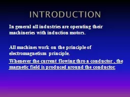
is connected to an ammeter A primary coil is connected to a battery A current can be produced by a changing magnetic field First shown in an experiment by Michael Faraday Faradays Experiment ID: 1024950

magnetic current loop emf current magnetic emf loop induced flux field circuit change law magnet time bar coil quiz

Share:

Link:

Embed:

Download Presentation from below link

Download Presentation The PPT/PDF document "Induced emf A secondary coil" is the property of its rightful owner. Permission is granted to download and print the materials on this web site for personal, non-commercial use only, and to display it on your personal computer provided you do not modify the materials and that you retain all copyright notices contained in the materials. By downloading content from our website, you accept the terms of this agreement.


Presentation Transcript

1.

2. Induced emfA secondary coil is connected to an ammeterA primary coil is connected to a batteryA current can be produced by a changing magnetic fieldFirst shown in an experiment by Michael Faraday

3. Faraday’s ExperimentThe purpose of the secondary circuit is to detect current that is produced by the magnetic fieldWhen the switch is closed, the ammeter deflects in one direction and then returns to zeroWhen the switch is opened, the ammeter deflects in the opposite direction and then returns to zeroWhen there is a steady current in the primary circuit, the ammeter reads zero

4. Faraday’s ConclusionsAn electrical current is produced by a changing magnetic fieldThe secondary circuit acts as if a source of emf were connected to it for a short timeIt is customary to say that an induced emf is produced in the secondary circuit by the changing magnetic field

5. Magnetic FluxThe emf is actually induced by a change in the quantity called the magnetic flux rather than simply by a change in the magnetic fieldMagnetic flux is defined similar to that of electrical fluxMagnetic flux is proportional to the strength of the magnetic field passing through the plane of a loop of wire and the area of the loop

6. Magnetic FluxThe magnetic flux through a loop of wire with area A is where B┴ is the component of B perpendicular to the plane of the loop and θ is the angle between B and the normal (perpendicular) to the plane of the loop The unit of magnetic flux is a Weber (Wb): 1 Wb = 1 T· m2

7. Magnetic FluxWhen the field is perpendicular to the plane of the loop θ = 0 and ΦB = ΦB, max = BAWhen the field is parallel to the plane of the loop θ = 90° and ΦB = 0The flux can be negative, for example, if θ = 180° ΦB = - BA

8. Magnetic FluxThe flux can be visualized with respect to magnetic field linesThe value of the magnetic flux is proportional to the total number of lines passing through the loopWhen the area is perpendicular to the lines, the maximum number of lines pass through the area and the flux is a maximumWhen the area is parallel to the lines, no lines pass through the area and the flux is 0

9. Electromagnetic Induction –An Experiment(a) When a magnet moves toward a loop of wire, the ammeter shows the presence of a current (b) When the magnet is held stationary, there is no current(c) When the magnet moves away from the loop, the ammeter shows a current in the opposite directionIf the loop is moved instead of the magnet, a current is also detected

10. Electromagnetic Induction – Results of the ExperimentA current is set up in the circuit as long as there is relative motion between the magnet and the loopThe same experimental results are found whether the loop moves or the magnet movesThe current is called an induced current because is it produced by an induced emf

11. Faraday’s Law and Electromagnetic InductionThe instantaneous emf induced in a circuit equals the negative of the rate of change of magnetic flux with respect to time through the circuitIf a circuit contains N tightly wound loops and the flux changes by ΔΦB during a time interval Δt, the average emf induced is given by Faraday’s Law:

12. The Ways to Induce emfThe emf induced in the loop of area A is An emf can be induced in the circuit in several ways: The magnitude of B can change with time The area enclosed by the loop can change with time The angle  between B and the normal to the loop can change with time Any combination of the above can occur

13. Lenz’s LawFaraday’s law indicates that induced emf and the change in flux have opposite algebraic signsThe physical interpretation of this statement is known as Lenz’s law: The induced current travels in the direction that creates a magnetic field with flux opposing the change in original magnetic flux through the circuitThat is, the induced current tends to maintain the original flux through the circuit

14. QUICK QUIZ 20.1The figure below is a graph of magnitude B versus time t for a magnetic field that passes through a fixed loop and is oriented perpendicular to the plane of the loop. Rank the magnitudes of the emf generated in the loop at the three instants indicated (a, b, c), from largest to smallest.

15. QUICK QUIZ 20.1 ANSWER(b), (c), (a). At each instant, the magnitude of the induced emf is proportional to the rate of change of the magnetic field (hence, proportional to the slope of the curve shown on the graph).

16. Applications of Faraday’s Law – Ground Fault InterruptersThe ground fault interrupter (GFI) is a safety device that protects against electrical shockThe iron ring confines the magnetic field, which is generally 0If a leakage occurs, the field is no longer 0 and the induced voltage triggers a circuit breaker shutting off the currentWire 1 leads from the wall outlet to the applianceWire 2 leads from the appliance back to the wall outlet

17. Electric Guitar

18. Applications of Faraday’s Law – Electric GuitarA vibrating string induces an emf in a coilA permanent magnet inside the coil magnetizes a portion of the string nearest the coilAs the string vibrates at some frequency, its magnetized segment produces a changing flux through the pickup coilThe changing flux produces an induced emf that is fed to an amplifier

19. Motional emf

20. Motional emfA straight conductor of length ℓ moves ( under the influence of some external agent) with constant velocity v perpendicularly through a uniform magnetic field B The electrons in the conductor experience a magnetic force: The electrons tend to move to the lower end of the conductorB

21. Motional emfAs the negative charges accumulate at the base, a net positive charge exists at the upper end of the conductorAs a result of this charge separation, an electric field E is produced in the conductorCharges build up at the ends of the conductor until the downward magnetic force is balanced by the upward electric force

22. Motional emfA potential difference is maintained across the conductor as long as there is motion through the fieldIf the motion is reversed, the polarity of the potential difference is also reversedThere is a potential difference between the upper and lower ends of the conductorThe upper end is at a higher potential than the lower end

23. Motional emf in a CircuitAs the bar is pulled to the right with constant velocity v under the influence of an applied force, Fapp, the free charges experience a magnetic force along the length of the barThis force sets up an induced current because the charges are free to move in the closed pathA circuit consists of a conducting bar of length ℓ sliding along two fixed parallel conducting railsAssume the moving bar has zero resistance

24. Motional emf in a CircuitThe magnitude of induced current isThe magnetic flux through the area isUse Faraday’s law:The induced, motional emf, acts like a battery in the circuit

25. QUICK QUIZ As an airplane flies due north from Los Angeles to Seattle, it cuts through Earth's magnetic field. As a result, an emf is developed between the wing tips. Which wing tip is positively charged?

26. QUICK QUIZ ANSWERThe left wingtip on the west side of the airplane. The magnetic field of the Earth has a downward component in the northern hemisphere. As the airplane flies northward, the right-hand rule indicates that positive charge experiences a force to the left side of the airplane. Thus, the left wingtip becomes positively charged and the right wingtip negatively charged.

27. QUICK QUIZ 20.3You wish to move a rectangular loop of wire into a region of uniform magnetic field at a given speed so as to induce an emf in the loop. The plane of the loop must remain perpendicular to the magnetic field lines. In which orientation should you hold the loop while you move it into the region of magnetic field in order to generate the largest emf? (a) With the long dimension of the loop parallel to the velocity vector; (b) With the short dimension of the loop parallel to the velocity vector. (c) Either way—the emf is the same regardless of orientation.

28. QUICK QUIZ 20.3 ANSWER(b). According to Equation 20.3, because B and v are constant, the emf depends only on the length of the wire moving in the magnetic field. Thus, you want the long dimension moving through the magnetic field lines so that it is perpendicular to the velocity vector. In this case, the short dimension is parallel to the velocity vector. From a more conceptual point of view, you want the rate of change of area in the magnetic field to be the largest, which you do by thrusting the long dimension into the field.

29. Lenz’ Law, Bar ExampleThe flux due to the external field in increasing into the pageThe flux due to the induced current must be out of the pageTherefore the current must be counterclockwise when the bar moves to the right

30. Lenz’ Law, Bar ExampleThe bar is moving toward the leftThe magnetic flux through the loop is decreasing with timeThe induced current must be clockwise to to produce its own flux into the page

31. Lenz’ Law Revisited, Conservation of EnergyAssume the bar is moving to the rightAssume the induced current is clockwise (opposite the direction required by Lenz’s law)The magnetic force on the bar would be to the rightThe force would cause an acceleration of the bar and the velocity would increaseThis would cause the flux to increase and the current to increase and the velocity to increase…This would violate Conservation of Energy and so therefore, the current must be counterclockwise

32. Lenz’ Law, Moving Magnet Example(a) A bar magnet is moved to the right toward a stationary loop of wire. As the magnet moves, the magnetic flux increases with time(b) The induced current produces a flux to the left, so the current is in the direction shown

33. Lenz’ Law, Final NoteWhen applying Lenz’ Law, there are two magnetic fields to considerThe external changing magnetic field that induces the current in the loopThe magnetic field produced by the current in the loop

34. QUICK QUIZ 20.4A bar magnet is falling through a loop of wire with constant velocity with the north pole entering first. Viewed from the same side of the loop as the magnet, as the north pole approaches the loop, the induced current will be in what direction? (a) clockwise (b) zero (c ) counterclockwise (d) along the length of the magnet

35. QUICK QUIZ 20.4 ANSWER(c). In order to oppose the approach of the north pole, the magnetic field generated by the induced current must be directed upward. An induced current directed counterclockwise around the loop will produce a field with this orientation along the axis of the loop.

36. Application – Tape Recorder

37. Application – Tape RecorderA magnetic tape moves past a recording and playback headThe tape is a plastic ribbon coated with iron oxide or chromium oxideTo record, the sound is converted to an electrical signal which passes to an electromagnet that magnetizes the tape in a particular patternTo playback, the magnetized pattern is converted back into an induced current driving a speaker

38. GeneratorsAlternating Current (AC) generatorConverts mechanical energy to electrical energyConsists of a wire loop rotated by some external meansThere are a variety of sources that can supply the energy to rotate the loopThese may include falling water, heat by burning coal to produce steam

39. AC GeneratorsBasic operation of the generatorAs the loop rotates, the magnetic flux through it changes with timeThis induces an emf and a current in the external circuitThe ends of the loop are connected to slip rings that rotate with the loopConnections to the external circuit are made by stationary brushed in contact with the slip rings

40. AC Generators

41. AC GeneratorsThe emf generated by the rotating loop can be found byIf the loop rotates with a constant angular speed, ω, and N turnsε = N B A ω sin ω tε = εmax when loop is parallel to the fieldε = 0 when when the loop is perpendicular to the field

42. DC GeneratorsComponents are essentially the same as that of an AC generatorThe major difference is the contacts to the rotating loop are made by a split ring, or commutator

43. DC GeneratorsThe output voltage always has the same polarityThe current is a pulsing currentTo produce a steady current, many loops and commutators around the axis of rotation are usedThe multiple outputs are superimposed and the output is almost free of fluctuations

44. MotorsMotors are devices that convert electrical energy into mechanical energyA motor is a generator run in reverseA motor can perform useful mechanical work when a shaft connected to its rotating coil is attached to some external device

45. Motors and Back emfThe phrase back emf is used for an emf that tends to reduce the applied currentWhen a motor is turned on, there is no back emf initiallyThe current is very large because it is limited only by the resistance of the coil

46. Motors and Back emfAs the coil begins to rotate, the induced back emf opposes the applied voltageThe current in the coil is reducedThe power requirements for starting a motor and for running it under heavy loads are greater than those for running the motor under average loads

47. Self-InductanceConsider a circuit: when the switch is thrown to its closed position, the current does not immediately jump from zero to its maximum value RAs the current increases, the magnetic flux through a loop due to this current also increasesThe increasing flux induces an emf that opposes the currentThis opposing emf results in a gradual increase of the current

48. Self-InductanceThis effect is called self-inductance because the changing flux through the circuit and resultant induced emf arise from the circuit itselfThe emf L set up in this case is called a self-induced emf

49. An Example of Self-Inductance (a) A current in the coil produces a magnetic field directed to the left (b) If the current increases, the increasing magnetic flux creates an induced emf in the coil having the polarity shown by the dashed battery(c) The polarity of the induced emf reverses if the current decreases

50. Self-InductanceThe self-induced emf must be proportional to the time rate of change of the currentL is a proportionality constant called the inductance of the deviceThe negative sign indicates that a changing current induces an emf in opposition to that change

51. Self-InductanceThe inductance of a coil depends on geometric factorsThe SI unit of self-inductance is the Henry 1 H = 1 V · s / AThe expression for L is

52. Inductance of a SolenoidLet the solenoid have N turns and length lL depends on the geometric factors l and A and on μ0 and is proportional to the square of the number of turns

53. Inductance of a SolenoidCan be also expressed in the formwhere V=Al is the volume of the solenoid

54. Inductor in a CircuitInductance can be interpreted as a measure of opposition to the rate of change in the currentRemember resistance R is a measure of opposition to the currentAs a circuit is completed, the current begins to increase, but the inductor produces an emf (back emf) that opposes the increasing currentTherefore, the current doesn’t change from 0 to its maximum instantaneously

55. RL CircuitsA series RL circuit: the elements connected to the battery are a resistor R and an inductor L

56. Suppose the switch is closed at t = 0: the current in the circuit begins to increase, and a back emf is induced in the inductorRL CircuitApply Kirchhoff’s loop rule to calculate the current in the circuit:A mathematical solution of this equation represents the current in the circuit as a function of time:

57. We can rewrite this expression asRL Circuitwhere  is the time constant of the RL circuit:When the switch is closed, the current increases to its equilibrium value  R according to an exponential function

58. RL CircuitWhen the current reaches its maximum, the rate of change and the back emf are zeroThe time constant, , for an RL circuit is the time required for the current in the circuit to reach 63.2% of its final value

59. QUICK QUIZ 20.5The switch in the circuit shown in the figure below is closed and the lightbulb glows steadily. The inductor is a simple air-core solenoid. An iron rod is inserted into the interior of the solenoid, which increases the magnitude of the magnetic field in the solenoid. As the rod is inserted into the solenoid, the brightness of the lightbulb (a) increases, (b) decreases, or (c) remains the same.

60. QUICK QUIZ 20.5 ANSWER(b). When the iron rod is inserted into the solenoid, the inductance of the coil increases. As a result, more potential difference appears across the coil than before. Consequently, less potential difference appears across the bulb and its brightness decreases.

61. Energy Stored in a Magnetic FieldThe emf induced by an inductor prevents a battery from establishing an instantaneous current in a circuitThe battery has to do work to produce a currentThis work can be thought of as energy stored by the inductor in its magnetic fieldThe energy stored in a charged capacitor