

CSE 461 University of Washington 2 Where we are in the Course Moving on to the Link Layer Physical Link Network Transport Application CSE 461 University of Washington 3 Scope of the Link Layer ID: 413974
Download Presentation The PPT/PDF document "Overview of the Link Layer" is the property of its rightful owner. Permission is granted to download and print the materials on this web site for personal, non-commercial use only, and to display it on your personal computer provided you do not modify the materials and that you retain all copyright notices contained in the materials. By downloading content from our website, you accept the terms of this agreement.

Slide1
Overview of the Link LayerSlide2
CSE 461 University of Washington
2
Where we are in the Course
Moving on to the Link Layer!
Physical
Link
Network
Transport
ApplicationSlide3
CSE 461 University of Washington
3
Scope of the Link Layer
Concerns how
to transfer messages over one or more connected links
Messages are
frames
, of limited sizeBuilds on the physical layer
FrameSlide4
In terms of layers …
CSE 461 University of Washington
4
Actual data path
Virtual data path
Network
Link
PhysicalSlide5
In terms of layers
CSE 461 University of Washington
5
Actual data path
Virtual data path
Network
Link
PhysicalSlide6
Typical Implementation
of Layers
CSE 461 University of Washington
6Slide7
CSE 461 University of Washington
7
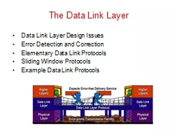
Topics
Framing
Delimiting start/end of frames
Error detection and correction
Handling errors
Retransmissions
Handling lossMultiple Access
802.11, classic EthernetSwitching
Modern Ethernet
LaterSlide8
Framing
(§3.1.2
)Slide9
CSE 461 University of Washington
9
Topic
The Physical layer gives us a stream of bits. How do we interpret it as a sequence of frames?
…
10110 …
Um?Slide10
CSE 461 University of Washington
10
Framing Methods
We’ll look at:
Byte count
»
Byte stuffing
»Bit stuffing »In practice, the physical layer often helps to identify frame boundaries
E.g., Ethernet, 802.11Slide11
CSE 461 University of Washington
11
Byte Count
First try:
Let’s start each frame with a length field!
It’s simple, and hopefully good enough …Slide12
Byte Count (2)
How well do you think it works?
CSE 461 University of Washington
12Slide13
Byte Count (3)
Difficult to re-synchronize after framing error
Want an easy way to scan for a start of frame
CSE 461 University of Washington
13Slide14
CSE 461 University of Washington
14
Byte Stuffing
Better idea:
Have a special flag byte value that means start/end of frame
Replace (“stuff”) the flag inside the frame with an escape code
Complication: have to escape the escape code too!Slide15
Byte Stuffing (2)
Rules
:
Replace each
FLAG in data with
ESC FLAGReplace each ESC
in data with ESC ESC
CSE 461 University of Washington
15Slide16
Byte Stuffing (3)
Now any
unescaped
FLAG is the start/end of a frame
CSE 461 University of Washington
16Slide17
CSE 461 University of Washington
17
Bit Stuffing
Can stuff at the bit level too
Assume a flag
has six consecutive
1s
On transmit, after five 1s in the data, insert a 0On receive, a 0 after five 1s is deleted Slide18
Bit Stuffing (2)
Example:
CSE 461 University of Washington
18
Transmitted bits
with stuffing
Data bitsSlide19
Bit Stuffing (3)
So how does it compare with byte stuffing?
CSE 461 University of Washington
19
Transmitted bits
with stuffing
Data bitsSlide20
CSE 461 University of Washington
20
Link Example: PPP over SONET
PPP is Point-to-Point Protocol
Widely used for link framing
E.g., it is used to frame IP packets that are sent over SONET optical linksSlide21
Link Example: PPP over SONET (2)
Think of SONET as a bit stream, and PPP as the framing that carries an IP packet over the link
CSE 461 University of Washington
21
Protocol stacks
PPP frames may be split over SONET payloadsSlide22
Link Example: PPP over SONET (3)
Framing uses byte stuffing
FLAG
is 0x7E and
ESC is 0x7D. To stuff (unstuff
) a byte, add (remove) ESC, and XOR byte with 0x20
CSE 461 University of Washington
22Slide23
Error Coding Overview (§3.2)Slide24
CSE 461 University of Washington
24
Topic
Some bits will be received in error due to noise. What can we do?
Detect errors with codes
»
Correct errors with codes
»Retransmit lost frames
Reliability is a concern that cuts across the layers – we’ll see it again
LaterSlide25
Problem – Noise may flip received bits
CSE 461 University of Washington
25
Signal
0
0
0
0
1
1
1
0
0
0
0
0
1
1
1
0
0
0
0
0
1
1
Slightly
Noisy
Very
noisy
0
1Slide26
CSE 461 University of Washington
26
Approach – Add Redundancy
Error detection codes
A
dd
check bits to the message bits to let some errors be detectedError correction codesAdd more check bits
to let some errors be correctedKey issue is now to structure the code to detect many errors with few check bits and modest computationSlide27
CSE 461 University of Washington
27
Motivating Example
A simple code to handle errors:
Send two copies! Error if different.
How good is this code?
How many errors can it detect/correct?
How many errors will make it fail? Slide28
CSE 461 University of Washington
28
Motivating Example (2)
We want to handle more errors with less overhead
Will look at better codes; they are applied mathematics
But, they can’t handle all errors
And they focus on accidental errors (will look at secure hashes later)Slide29
CSE 461 University of Washington
29
Using Error Codes
Codeword
consists of D data plus R check bits (=systematic block code)
Sender:
C
ompute R check bits based on the D data bits; send the codeword of D+R bits
D
R=
fn
(D)
D
ata bits
Check bitsSlide30
CSE 461 University of Washington
30
Using Error Codes (2)
Receiver:
Receive D+R bits with unknown errors
Recompute
R check bits based on the D data bits; error if R doesn’t match R’
D
R’
D
ata bits
C
heck bits
R=
fn
(D)
=?Slide31
CSE 461 University of Washington
31
R.W. Hamming (1915-1998)
Much early work on codes:
“Error Detecting and Error Correcting Codes”, BSTJ, 1950
See also:
“You and Your Research”, 1986
Source: IEEE GHN, © 2009, IEEESlide32
CSE 461 University of Washington
32
Intuition for Error Codes
For D data bits, R check bits:
Randomly chosen
codeword
is unlikely to be correct; overhead is low
All
codewords
Correct
codewordsSlide33
CSE 461 University of Washington
33
Hamming Distance
Distance is the number of bit flips needed to change D
1
to D
2
Hamming distance of a code is the minimum distance between any pair of codewordsSlide34
CSE 461 University of Washington
34
Hamming Distance (2)
Error detection:
For a code of distance d+1, up to d errors will always be detectedSlide35
CSE 461 University of Washington
35
Hamming Distance (3)
Alternatively, error correction:
For a code of distance 2d+1, up to d errors can always be correctedSlide36
Error Detection (§3.2.2)Slide37
CSE 461 University of Washington
37
Topic
Some bits may be received in error due to noise. How do we detect this?
Parity
»
Checksums
»CRCs »
Detection will let us fix the error, for example, by retransmission (later).Slide38
CSE 461 University of Washington
38
Simple Error Detection – Parity Bit
Take D data bits, add 1 check bit that is the sum of the D bits
Sum is modulo 2 or XORSlide39
CSE 461 University of Washington
39
Parity Bit (2)
How well does parity work?
What is the distance of the code?
How many errors will it detect/correct?
What about larger errors? Slide40
CSE 461 University of Washington
40
Checksums
Idea: sum up data in N-bit words
Widely used in, e.g., TCP/IP/UDP
Stronger protection than parity
1500 bytes
16 bitsSlide41
CSE 461 University of Washington
41
Internet Checksum
Sum is defined in 1s complement arithmetic (must add back carries)
And it’s the negative sum
“
The
checksum field is the 16 bit one's complement of the one's complement sum of all 16 bit words …” – RFC 791Slide42
CSE 461 University of Washington
42
Internet Checksum (2)
Sending
:
Arrange data in 16-bit
words
Put zero in checksum position, addAdd any carryover back to get 16 bits
Negate (complement) to get sum
0001
f203
f4f5 f6f7
+(0000)------
2ddf0
ddf0 + 2
------ ddf2
220d Slide43
CSE 461 University of Washington
43
Internet Checksum (3)
Sending
:
Arrange data in 16-bit words
Put zero in checksum position, add
Add any carryover back to get 16 bits
Negate (complement) to get sum
0001
f203 f4f5
f6f7 +(0000)
------ 2ddf0
ddf0
+ 2 ------
ddf2
220d Slide44
CSE 461 University of Washington
44
Internet Checksum (4)
Receiving
:
Arrange data in 16-bit words
Checksum will be non-zero, add
Add any carryover back to get 16 bits
Negate the result and check it is 0
0001
f203
f4f5
f6f7
+ 220d ------
2fffd
fffd
+ 2
------
ffff
0000 Slide45
CSE 461 University of Washington
45
Internet Checksum (5)
Receiving
:
Arrange data in 16-bit words
Checksum will be non-zero, add
Add any carryover back to get 16 bits
Negate the result and check it is 0
0001
f203
f4f5
f6f7
+ 220d ------
2fffd
fffd
+ 2
------
ffff
0000 Slide46
CSE 461 University of Washington
46
Internet Checksum (6)
How well does
the checksum work
?
What is the distance of the code?
How many errors will it detect/correct? What about larger errors? Slide47
CSE 461 University of Washington
47
Cyclic Redundancy Check (CRC)
Even stronger protection
Given n data bits, generate k check bits such that the
n+k
bits are evenly divisible by a generator C
Example with numbers:n = 302, k = one digit, C = 3Slide48
CSE 461 University of Washington
48
CRCs (2)
The catch:
It’s based on mathematics of finite fields, in which “numbers” represent polynomials
e.g
, 10011010 is x
7 + x4 + x3 + x1
What this means:We work with binary values and operate using modulo 2 arithmeticSlide49
CSE 461 University of Washington
49
CRCs (2)
Send Procedure:
Extend the n data bits with k zeros
Divide by the generator value C
Keep remainder, ignore quotient
Adjust k check bits by remainder
Receive Procedure:Divide and check for zero remainderSlide50
CRCs (3)
CSE 461 University of Washington
50
Data bits:
1101011111
Check bits:
C(x)=x
4+x1+1
C = 10011k = 4
1 0 0 1 1 1 1 0 1 0
1 1 1 1 1 Slide51
CRCs (3)
CSE 461 University of Washington
51Slide52
CSE 461 University of Washington
52
CRCs (4)
Protection depend on generator
Standard CRC-32 is 10000010 01100000 10001110 110110111
Properties:
HD=4, detects up to triple bit errorsAlso odd number of errors And bursts of up to k bits in errorNot vulnerable to systematic errors like checksumsSlide53
CSE 461 University of Washington
53
Error Detection in Practice
CRCs are widely used on links
Ethernet, 802.11, ADSL, Cable …
C
hecksum used in Internet
IP, TCP, UDP … but it is weakParityIs little usedSlide54
CSE 461 University of Washington
54
Announcements
Hints for Project 1
Next assignment:
Wireshark
lab
Midterm date: Feb 8thCoursera QuizesSlide55
Error Correction (§3.2.3)Slide56
CSE 461 University of Washington
56
Topic
Some bits may be received in error due to noise. How do we fix them?
Hamming code
»
Other codes
»And why should we use detection when we can use correction?Slide57
CSE 461 University of Washington
57
Why Error Correction is Hard
If we had reliable check bits we could use them to narrow down the position of the error
Then correction would be easy
But error could be in the check bits as well as the data bits!
Data might even be correct Slide58
CSE 461 University of Washington
58
Intuition for Error Correcting Code
Suppose we construct a code with a Hamming distance of at least 3
Need ≥3 bit errors to change one valid
codeword
into another
Single bit errors will be closest to a unique valid codewordIf we assume errors are only 1 bit, we can correct them by mapping an error to the closest valid
codewordWorks for d errors if HD ≥ 2d 1Slide59
CSE 461 University of Washington
59
Intuition
(2)
Visualization of code:
A
B
Valid
c
odeword
Error
codewordSlide60
CSE 461 University of Washington
60
Intuition
(3)
Visualization of code:
A
B
Valid
c
odeword
Error
codeword
Single
b
it error
f
rom A
Three bit
errors to
get to BSlide61
CSE 461 University of Washington
61
Hamming Code
Gives a method for constructing a code with a distance of 3
Uses k check bits for 2
k-1
data bits
Put check bits in positions p that are powers of 2, starting with position 1Check bit in position p is parity of positions with a p term in their values
Plus an easy way to correct [soon]Slide62
CSE 461 University of Washington
62
Hamming Code (2)
Example: data=0101, 3 check bits
7 bit code, check bit positions 1, 2, 4
Check 1 covers positions 1, 3, 5, 7
Check 2 covers positions 2, 3, 6, 7
Check 4 covers positions 4, 5, 6, 7
_
_ _ _ _ _ _
1 2 3 4 5 6 7Slide63
CSE 461 University of Washington
63
Hamming Code (3)
Example: data=0101, 3 check bits
7 bit code, check bit positions 1, 2, 4
Check 1 covers positions 1, 3, 5, 7
Check 2 covers positions 2, 3, 6, 7
Check 4 covers positions 4, 5, 6, 7
0
1 0 0 1 0 1
p1= 0+1+1 = 0, p2= 0+0+1 = 1, p4
= 1+0+1 = 0
1 2 3 4 5 6 7Slide64
CSE 461 University of Washington
64
Hamming Code (4)
To decode:
Recompute
check bits (with parity sum including the check bit)
Arrange as a binary number
Value (syndrome) tells error positionValue of zero means no errorOtherwise, flip bit to correctSlide65
CSE 461 University of Washington
65
Hamming Code (5)
Example, continued
0
1
0 0 1 0 1p1= p2
= p4= Syndrome =
Data =
1 2 3 4 5 6 7Slide66
CSE 461 University of Washington
66
Hamming Code (6)
Example, continued
0
1
0 0 1 0 1p1= 0+0+1+1 = 0, p2
= 1+0+0+1 = 0,p4= 0+1+0+1 = 0Syndrome = 000, no error
Data = 0 1 0 1
1 2 3 4 5 6 7Slide67
CSE 461 University of Washington
67
Hamming Code (7)
Example, continued
0
1
0 0 1 1 1p1
= p2= p4=
Syndrome = Data =
1 2 3 4 5 6 7Slide68
CSE 461 University of Washington
68
Hamming Code (8)
Example, continued
0
1
0 0 1 1 1p1
= 0+0+1+1 = 0, p2= 1+0+1+1 =
1,p4= 0+1+1
+1 = 1Syndrome = 1 1
0, flip position 6Data = 0 1 0 1 (correct after flip!)
1 2 3 4 5 6 7Slide69
CSE 461 University of Washington
69
Other Error Correction Codes
Codes used in practice are much more involved than Hamming
Convolutional codes (§3.2.3)
Take a stream of data and output a mix of the recent input bits
Makes each output bit less fragile
Decode using Viterbi algorithm (which can use bit confidence values)Slide70
CSE 461 University of Washington
70
Other Codes (2) – LDPC
Low Density Parity Check (§
3.2.3)
LDPC based
on sparse
matricesDecoded iteratively using a belief propagation algorithmState of the art todayInvented by Robert Gallager in 1963 as part of his PhD thesis
Promptly forgotten until 1996 …
Source: IEEE GHN, © 2009, IEEESlide71
CSE 461 University of Washington
71
Detection vs. Correction
Which is better will depend on the pattern of errors. For example:
1000 bit messages with a
bit error rate
(
BER) of 1 in 10000Which has less overhead?Slide72
CSE 461 University of Washington
72
Detection vs. Correction
Which is better will depend on the pattern of errors. For example:
1000 bit messages with a
bit error rate
(
BER) of 1 in 10000Which has less overhead?It depends! We need to know more about the errorsSlide73
CSE 461 University of Washington
73
Detection vs. Correction (2)
Assume bit errors are random
Messages have 0 or maybe 1 error
Error correction:
Need ~10 check bits per message
Overhead:Error detection: Need ~1 check bits per message plus 1000 bit retransmission 1/10 of the time
Overhead:Slide74
CSE 461 University of Washington
74
Detection vs. Correction (3)
Assume errors come in bursts of 100
Only 1 or 2 messages in 1000 have errors
Error correction:
Need >>100 check bits per message
Overhead:Error detection: Need 32? check bits per message plus 1000 bit resend 2/1000 of the time
Overhead:Slide75
CSE 461 University of Washington
75
Detection vs. Correction (4)
Error correction:
Needed when errors are expected
Or when no time for retransmission
Error detection:
More efficient when errors are not expectedAnd when errors are large when they do occurSlide76
CSE 461 University of Washington
76
Error Correction in Practice
Heavily used in physical layer
Convolutional codes widely used in practice
LDPC is the future, used for demanding links like 802.11, DVB,
WiMAX
, LTE, power-line, …Error detection (w/ retransmission) is used in the link layer and above for residual errorsAlso used in the application layer
With an erasure error modelE.g., Reed-Solomon (CDs, DVDs, etc.)Slide77
Retransmissions (ARQ) (§3.3)Slide78
CSE 461 University of Washington
78
Topic
Two strategies to handle errors:
Detect errors and retransmit frame (Automatic Repeat
reQuest
, ARQ)
Correct errors with an error correcting code
Done thisSlide79
CSE 461 University of Washington
79
ARQ
ARQ often used when errors are common or must be corrected
E.g.,
WiFi
, and TCP (later)
Rules at sender and receiver:Receiver automatically acknowledges correct frames with an ACKSender automatically resends after a timeout, until an ACK is receivedSlide80
CSE 461 University of Washington
80
ARQ (2)
Normal operation (no loss)
Frame
ACK
Timeout
Time
Sender
ReceiverSlide81
CSE 461 University of Washington
81
ARQ (3)
Loss and retransmissio
n
Frame
Timeout
Time
Sender
Receiver
Frame
ACK
XSlide82
CSE 461 University of Washington
82
So What’s Tricky About ARQ?
Two non-trivial issues:
How long to set the timeout?
»
How to avoid accepting duplicate frames as new frames
»Want performance in the common case and correctness alwaysSlide83
CSE 461 University of Washington
83
Timeouts
Timeout should be:
Not too big (link goes idle)
Not too small (spurious resend)
Fairly easy on a LAN
Clear worst case, little variationFairly difficult over the InternetMuch variation, no obvious boundWe’ll revisit this with TCP (later)Slide84
CSE 461 University of Washington
84
Duplicates
What happens if an ACK is lost?
X
Frame
ACK
Timeout
Sender
Receiver
New
Frame?Slide85
CSE 461 University of Washington
85
Duplicates (2)
What happens if an ACK is lost?
Frame
ACK
X
Frame
ACK
Timeout
Sender
Receiver
New
Frame?
New
Frame??Slide86
CSE 461 University of Washington
86
Duplicates (3)
Or the timeout is early?
ACK
Frame
Timeout
Sender
Receiver
New
Frame?Slide87
CSE 461 University of Washington
87
Duplicates (4)
Or the timeout is early?
Frame
ACK
Frame
ACK
Timeout
Sender
Receiver
New
Frame?
New
Frame??Slide88
CSE 461 University of Washington
88
Sequence Numbers
Frames and ACKs must both carry sequence numbers for correctness
To distinguish the current frame from the next one, a single bit (two numbers) is sufficient
Called
Stop-and-WaitSlide89
CSE 461 University of Washington
89
Stop-and-Wait
In the normal case:
Time
Sender
ReceiverSlide90
CSE 461 University of Washington
90
Stop-and-Wait (2)
In the normal case:
Frame 0
ACK 0
Timeout
Time
Sender
Receiver
Frame 1
ACK 1Slide91
CSE 461 University of Washington
91
Stop-and-Wait (3)
With ACK loss:
X
Frame 0
ACK 0
Timeout
Sender
Receiver
New
Frame?Slide92
CSE 461 University of Washington
92
Stop-and-Wait (4)
With ACK loss:
Frame 0
ACK 0
X
Frame 0
ACK 0
Timeout
Sender
Receiver
New
Frame?
It’s a
Resend!Slide93
CSE 461 University of Washington
93
Stop-and-Wait (5)
With early timeout:
ACK 0
Frame 0
Timeout
Sender
Receiver
New
Frame?Slide94
CSE 461 University of Washington
94
Stop-and-Wait (6)
With early timeout:
Frame 0
ACK 0
Frame 0
ACK 0
Timeout
Sender
Receiver
New
Frame?
It’s a
Resend
OK …Slide95
CSE 461 University of Washington
95
Limitation of Stop-and-Wait
It allows only a single frame to be outstanding from the sender:
Good for LAN, not efficient for high BD
Ex: R=1 Mbps, D = 50
ms
How many frames/sec? If R=10 Mbps?Slide96
CSE 461 University of Washington
96
Sliding Window
Generalization of stop-and-wait
Allows W frames to be outstanding
Can send W frames per
RTT
Various options for numbering frames/ACKs and handling loss
Will look at along with TCP (later)Slide97
Multiplexing(§2.5.3, 2.5.4)Slide98
Topic
Multiplexing is the network word for the sharing of a resource
Classic scenario is sharing a link among different users
Time Division Multiplexing (TDM)
»
Frequency Division Multiplexing (FDM) »
CSE 461 University of Washington
98Slide99
Time Division Multiplexing (TDM)
Users take turns on a fixed schedule
CSE 461 University of Washington
99
2
2
2
2Slide100
Frequency Division Multiplexing (FDM)
Put different users on different frequency bands
CSE 461 University of Washington
100
Overall FDM channelSlide101
CSE 461 University of Washington
101
TDM versus FDM
In TDM a user sends at a high rate a fraction of the time; in FDM, a user sends at a low rate all the time
Rate
Time
FDM
T
DMSlide102
CSE 461 University of Washington
102
TDM versus FDM (2)
In TDM a user sends at a high rate a fraction of the time; in FDM, a user sends at a low rate all the time
Rate
Time
FDM
T
DMSlide103
CSE 461 University of Washington
103
TDM/FDM Usage
Statically divide a resource
Suited for continuous traffic, fixed number of users
Widely used in telecommunications
TV and radio stations (FDM)
GSM (2G cellular) allocates calls using TDM within FDMSlide104
CSE 461 University of Washington
104
Multiplexing Network Traffic
Network traffic is
bursty
ON/OFF
sources
Load varies greatly over time
Rate
Time
Rate
TimeSlide105
CSE 461 University of Washington
105
Multiplexing Network
Traffic (2)
Network traffic is
bursty
Inefficient to always allocate user their
ON needs with TDM/FDM
Rate
Time
Rate
Time
R
RSlide106
Multiplexing Network
Traffic (3)
Multiple
access
schemes multiplex users according to their demands – for gains of statistical multiplexing
CSE 461 University of Washington
106
Rate
Time
Rate
Time
Rate
Time
R
R
R’<2R
Two users, each need R
Together they need R’ < 2RSlide107
CSE 461 University of Washington
107
Multiple Access
We will look at two kinds of multiple access protocols
Randomized. Nodes randomize their resource access attempts
Good for low load situations
Contention-free. Nodes order their resource access attempts
Good for high load or guaranteed quality of service situationsSlide108
Randomized Multiple Access (§4. 2.1-4.2.2, 4.3.1-4.3.3)Slide109
CSE 461 University of Washington
109
Topic
How do nodes share a single link? Who sends when, e.g., in
WiFI
?
Explore with a simple model
Assume no-one is in charge; this is a distributed systemSlide110
CSE 461 University of Washington
110
Topic (2)
We will explore random
multiple access control
(MAC) protocols
This is the basis for
classic EthernetRemember: data traffic is bursty
Zzzz..
Busy!
Ho humSlide111
CSE 461 University of Washington
111
ALOHA Network
Seminal computer network connecting the Hawaiian islands in the late 1960s
When should nodes send?
A
new protocol was devised by Norm Abramson …
HawaiiSlide112
CSE 461 University of Washington
112
ALOHA Protocol
Simple idea:
Node just sends when it has traffic.
If there was a collision (no ACK received) then wait a random time and resend
That’s it!Slide113
CSE 461 University of Washington
113
ALOHA Protocol (2)
Some frames will be lost, but many may get through…
Good idea?
Slide114
CSE 461 University of Washington
114
ALOHA Protocol (3)
Simple, decentralized protocol that works well under low load!
Not efficient under high load
Analysis shows at most 18% efficiency
Improvement: divide time into slots and efficiency goes up to 36%
We’ll look at other improvementsSlide115
CSE 461 University of Washington
115
Classic Ethernet
ALOHA inspired Bob Metcalfe to invent Ethernet for LANs in 1973
Nodes share 10 Mbps coaxial cable
Hugely popular in 1980s, 1990s
: © 2009 IEEESlide116
CSE 461 University of Washington
116
CSMA (Carrier Sense Multiple Access)
Improve ALOHA by listening for activity before we send (
Doh
!)
Can do easily with wires, not wireless
So does this eliminate collisions?Why or why not?Slide117
CSE 461 University of Washington
117
CSMA (2)
Still possible to listen and hear nothing when another node is sending because of delay
CSMA is a good defense against collisions only when BD is smallSlide118
CSE 461 University of Washington
118
CSMA (3)
Still possible to listen and hear nothing when another node is sending because of delay
CSMA is a good defense against collisions only when BD is small
XSlide119
CSE 461 University of Washington
119
CSMA/CD (with Collision Detection)
Can reduce the cost of collisions by detecting them and aborting (Jam) the rest of the frame time
Again, we can do this with wires
X
X
X
X
X
X
X
X
Jam!
Jam!Slide120
CSE 461 University of Washington
120
CSMA/CD Complications
Want everyone who collides to know that it happened
Time window in which a node may hear of a collision is 2D seconds
XSlide121
CSE 461 University of Washington
121
CSMA/CD Complications (2)
Impose a minimum frame size that lasts for 2D
seconds
So node can’t finish before collision
Ethernet minimum frame is 64 bytes
XSlide122
CSE 461 University of Washington
122
CSMA “Persistence”
What should a node do if another node is sending?
Idea:
Wait
until it is done,
and send
What now?Slide123
CSE 461 University of Washington
123
CSMA “Persistence” (2)
Problem is that multiple waiting nodes will queue up then collide
More load, more of a problem
Now!
Now!
Uh ohSlide124
CSE 461 University of Washington
124
CSMA “Persistence” (3)
Intuition for a better solution
If there are N queued senders, we want each to send next with probability 1/N
Send p=½
Whew
Send p=½Slide125
CSE 461 University of Washington
125
Binary Exponential Backoff (BEB)
Cleverly estimates the probability
1st collision, wait 0 or 1 frame times
2nd collision, wait from 0 to 3 times
3rd collision, wait from 0 to 7 times …
BEB doubles interval for each successive collisionQuickly gets large enough to workVery efficient in practiceSlide126
Classic Ethernet, or IEEE 802.3
Most popular LAN of the 1980s, 1990s
10 Mbps over shared coaxial cable, with baseband signals
Multiple access with “1-persistent CSMA/CD with BEB”
CSE 461 University of Washington
126Slide127
Ethernet Frame Format
Has addresses to identify the sender and receiver
CRC-32 for error detection; no ACKs or retransmission
Start of frame identified with physical layer preamble
CSE 461 University of Washington
127
Packet from Network layer (IP)Slide128
CSE 461 University of Washington
128
Modern Ethernet
Based on switches, not multiple access, but still called Ethernet
We’ll get to it in a later segment
Switch
Twisted pair
Switch portsSlide129
Wireless Multiple Access (§4.2.5, 4.4)Slide130
CSE 461 University of Washington
130
Topic
How do wireless nodes share a single link? (Yes, this is
WiFi
!)
Build on our simple, wired model
Send?
Send?Slide131
CSE 461 University of Washington
131
Wireless Complications
Wireless is more complicated than the wired case (Surprise!)
Nodes may have different areas of coverage – doesn’t fit Carrier Sense
»
Nodes can’t hear while sending – can’t Collision Detect
»
≠ CSMA/CDSlide132
CSE 461 University of Washington
132
Different Coverage Areas
Wireless signal is broadcast and received nearby, where there is sufficient SNRSlide133
Hidden Terminals
Nodes A and C are
hidden terminals
when sending to B
Can’t hear each other (to coordinate) yet collide at B
We want to avoid the inefficiency of collisions
CSE 461 University of Washington
133Slide134
Exposed Terminals
B and C are
exposed terminals
when sending to A and D
Can hear each other yet don’t collide at receivers A and D
We want to send concurrently to increase performance
CSE 461 University of Washington
134Slide135
CSE 461 University of Washington
135
Nodes Can’t Hear While Sending
With wires, detecting collisions (and aborting) lowers their cost
More wasted time with wireless
Time
XXXXXXXXX
XXXXXXXXX
Wireless
Collision
Resend
X
X
Wired
Collision
ResendSlide136
Possible Solution: MACA
MACA uses a short handshake instead of CSMA (
Karn
, 1990)
802.11 uses a refinement of MACA (later)
Protocol rules:A sender node transmits a RTS (Request-To-Send, with frame length)
The receiver replies with a CTS (Clear-To-Send, with frame length)S
ender transmits the frame while nodes hearing the CTS stay silentCollisions on the RTS/CTS are still possible, but less likelyCSE 461 University of Washington
136Slide137
CSE 461 University of Washington
137
MACA – Hidden Terminals
A
B with h
idden terminal C
A sends RTS, to B
D
C
B
ASlide138
CSE 461 University of Washington
138
MACA – Hidden
Terminals (2)
A
B with h
idden terminal C
B sends CTS, to A, and C too
D
C
B
A
RTSSlide139
CSE 461 University of Washington
139
MACA – Hidden
Terminals (3)
A
B with h
idden terminal C
B sends CTS, to A, and C too
D
C
B
A
RTS
C
TS
C
TS
Alert!Slide140
CSE 461 University of Washington
140
MACA – Hidden
Terminals (4)
A
B with h
idden terminal C
A sends frame while C defers
Frame
Quiet...Slide141
CSE 461 University of Washington
141
MACA – Exposed Terminals
BA, CD as exposed terminals
B and C send RTS to A and D
D
C
B
ASlide142
CSE 461 University of Washington
142
MACA – Exposed Terminals (2)
BA, CD as exposed terminals
A and D send CTS to B and C
D
C
B
A
RTS
RTSSlide143
CSE 461 University of Washington
143
MACA – Exposed Terminals (3)
BA, CD as exposed terminals
A and D send CTS to B and C
D
C
B
A
RTS
RTS
C
TS
C
TS
All OK
All OKSlide144
CSE 461 University of Washington
144
MACA – Exposed Terminals (4)
BA, CD as exposed terminals
A and D send CTS to B and C
D
C
B
A
Frame
FrameSlide145
CSE 461 University of Washington
145
802.11, or WiFi
Very popular wireless LAN started in the 1990s
Clients get connectivity from a (wired) AP (Access Point)
It’s a multi-access problem
Various flavors have been developed over timeFaster, more features
Access
Point
Client
To NetworkSlide146
CSE 461 University of Washington
146
802.11 Physical Layer
Uses 20/40 MHz channels on ISM bands
802.11b/g/n on 2.4 GHz
802.11 a/n on 5 GHz
OFDM modulation (except legacy 802.11b)
Different amplitudes/phases for varying SNRsRates from 6 to 54 Mbps plus error correction802.11n uses multiple antennas; see “802.11 with Multiple Antennas for Dummies”Slide147
802.11 Link Layer
Multiple access uses CSMA/CA (next); RTS/CTS optional
Frames are
ACKed
and retransmitted with ARQ
Funky addressing (three addresses!) due to AP
Errors are detected with a 32-bit CRC
Many, many features (e.g., encryption, power save)
CSE 461 University of Washington147
Packet from Network layer (IP)Slide148
802.11 CSMA/CA for Multiple Access
Sender avoids collisions by inserting small random gaps
E.g., when both B and C send, C picks a smaller gap, goes first
CSE 461 University of Washington
148
Time
Send?
Send?Slide149
The Future of 802.11 (Guess)
L
ikely ubiquitous for Internet connectivity
Greater diversity, from low- to high-end devices
Innovation in physical layer drives speedAnd power-efficient operation too
More seamless integration of connectivityToo manual now, and limited (e.g., device-to-device)
CSE 461 University of Washington
149Slide150
Contention-Free Multiple Access (§4.2.3)Slide151
CSE 461 University of Washington
151
Topic
A new approach to multiple access
Based on turns, not randomization
1
3
2
4 Slide152
CSE 461 University of Washington
152
Issues with Random Multiple Access
CSMA is good under low load:
Grants immediate access
Little overhead (collisions)
But not so good under high load:
High overhead (expect collisions)Access time varies (lucky/unlucky)We want to do better under load!Slide153
CSE 461 University of Washington
153
Turn-Taking Multiple Access Protocols
They define an order in which nodes get a chance to send
Or pass, if no traffic at present
We just need some ordering …
E.g., Token Ring
»E.g., node addressesSlide154
Token Ring
Arrange nodes in a ring; token rotates “permission to send” to each node in turn
CSE 461 University of Washington
154
Node
Direction of
transmission
TokenSlide155
CSE 461 University of Washington
155
Turn-Taking Advantages
Fixed overhead with no collisions
More efficient under load
Regular chance to send with no unlucky nodes
Predictable service, easily extended to guaranteed quality of serviceSlide156
CSE 461 University of Washington
156
Turn-Taking Disadvantages
Complexity
More things that can go wrong than random access protocols!
E.g., what if the token is lost?
Higher overhead at low loadSlide157
CSE 461 University of Washington
157
Turn-Taking in Practice
Regularly tried as an improvement offering better service
E.g., qualities of service
But random multiple access is hard to beat
Simple,
and usually good enoughScales from few to many nodesSlide158
CSE 461 University of Washington
158
Announcements
Wireshark
homework due on Friday, come to office hours if you have questions
No class on Friday
Material for next week’s exam: everything including next topic on switches, spanning treeSlide159
LAN Switches (§4.x)Slide160
CSE 461 University of Washington
160
Topic
How do we connect nodes with a
switch
instead of multiple access
Uses multiple links/wires
Basis of modern (switched) Ethernet
SwitchSlide161
CSE 461 University of Washington
161
Switched Ethernet
Hosts are wired to Ethernet switches with twisted pair
Switch serves to connect the hosts
Wires usually run to a closet
Switch
Twisted pair
Switch portsSlide162
CSE 461 University of Washington
162
What’s in the box?
Remember from protocol layers:
Network
Link
Network
Link
Link
Link
Physical
Physical
Hub, or
repeater
Switch
Router
All look like this:Slide163
Inside a Hub
All ports are wired together; more convenient and reliable than a single shared wire
CSE 461 University of Washington
163
↔Slide164
Inside a Switch
Uses frame addresses to connect input port to the right output port; multiple frames may be switched in parallel
CSE 461 University of Washington
164
. . .
FabricSlide165
Inside a Switch (2)
Port may be used for both input and output (full-duplex)
Just send, no multiple access protocol
CSE 461 University of Washington
165
. . .
1
2
3
4
1
4
a
nd
2 3Slide166
Inside a Switch (3)
Need buffers for multiple inputs to send to one output
CSE 461 University of Washington
166
. . .
. . .
. . .
. . .
Input Buffer
Output Buffer
Fabric
Input
OutputSlide167
Inside a Switch (4)
Sustained overload will fill buffer and lead to frame loss
CSE 461 University of Washington
167
. . .
. . .
. . .
. . .
Input Buffer
Output Buffer
Fabric
Input
Output
XXX
Loss!Slide168
CSE 461 University of Washington
168
Advantages of Switches
Switches and hubs have replaced the shared cable of classic Ethernet
C
onvenient to run wires to one location
More reliable; wire cut is not a single point of failure that is hard to find
Switches offer scalable performanceE.g., 100 Mbps per port instead of 100 Mbps for all nodes of shared cable / hubSlide169
Switch Forwarding
Switch needs to find the right output port for the destination address in the Ethernet frame. How?
Want to let hosts be moved around readily; don’t look at IP
CSE 461 University of Washington
169
. . .
. . .
. . .
. . .
Source
Destination
Ethernet FrameSlide170
CSE 461 University of Washington
170
Backward Learning
Switch forwards frames with a port/address table as follows:
To fill the table, it looks at the source address of input frames
To forward, it sends to the port, or else broadcasts to all portsSlide171
CSE 461 University of Washington
171
Backward Learning (2)
1: A sends to D
Switch
D
Address
Port
A
B
C
DSlide172
CSE 461 University of Washington
172
Backward Learning (3)
2: D sends to A
Switch
D
Address
Port
A
1
B
C
DSlide173
CSE 461 University of Washington
173
Backward Learning (4)
3: D sends to A
Switch
D
Address
Port
A
1
B
C
D
4Slide174
CSE 461 University of Washington
174
Backward Learning (5)
3: D sends to A
Switch
D
Address
Port
A
1
B
C
D
4Slide175
Learning with Multiple Switches
Just works with multiple switches and a mix of hubs,
assuming no loops
in the topology, E.g., A sends to D
CSE 461 University of Washington
175
SwitchSlide176
Learning with Multiple Switches (2)
Just works with multiple switches and a mix of hubs
assuming no loo
ps,
e.g., A sends to D then D sends to A
CSE 461 University of Washington
176
SwitchSlide177
Switch Spanning Tree (§4.x)Slide178
CSE 461 University of Washington
178
Topic
How can we connect switches in any topology so they just work
This is part 2 of switched Ethernet
Loops – yikes!Slide179
CSE 461 University of Washington
179
Problem – Forwarding Loops
May have a loop in the topology
Redundancy in case of failures
Or a simple mistake
Want LAN switches to “just work”
Plug-and-play, no changes to hostsBut loops cause a problem …
Redundant
L
inksSlide180
CSE 461 University of Washington
180
Forwarding Loops (2)
Suppose the network is started and A sends to F. What happens?
Left / Right
A
B
C
D
E
FSlide181
CSE 461 University of Washington
181
Forwarding Loops (3)
Suppose the network is started and A sends to F. What happens?
A
C B, D-left, D-right
D-left C-right, E, F
D-right C-left, E, FC-right D-left, A, B
C-left D-right, A, BD-left …D-right …
Left / Right
A
B
C
D
E
FSlide182
CSE 461 University of Washington
182
Spanning Tree Solution
S
witches collectively find a
spanning tree
for the topology
A subset of links that is a tree (no loops) and reaches all switchesThen switches forward as normal on the spanning treeBroadcasts will go up to the root of the tree and down all the branchesSlide183
Spanning Tree (2)
CSE 461 University of Washington
183
Topology
One ST
Another STSlide184
Spanning Tree (3)
CSE 461 University of Washington
184
Topology
One ST
Another ST
RootSlide185
CSE 461 University of Washington
185
Spanning Tree Algorithm
Rules of the distributed game:
All switches run the same algorithm
They start with no information
Operate in parallel and send messages
Always search for the best solutionEnsures a highly robust solutionAny topology, with no configurationA
dapts to link/switch failures, …Slide186
CSE 461 University of Washington
186
Radia Perlman (1952–)
Key early work on routing protocols
Routing in the ARPANET
Spanning Tree for switches (next)
Link-state routing (later)
Now focused on network securitySlide187
CSE 461 University of Washington
187
Spanning Tree Algorithm (2)
Outline:
Elect a root node of the tree (switch with the lowest address)
Grow tree as shortest distances from the root (using lowest address to break distance ties)
Turn off ports for forwarding if they aren’t on the spanning treeSlide188
Spanning Tree Algorithm (3)
Details:
Each switch initially believes it is the root of the tree
Each switch sends periodic updates to neighbors with:
Its address, address of the root, and distance (in hops) to root
Switches favors ports with shorter distances to lowest root
Uses lowest address as a tie for distances
CSE 461 University of Washington
188
C
Hi, I’m
C
, the root is
A
, it’s
2
hops away
o
r (C, A, 2)Slide189
CSE 461 University of Washington
189
Spanning Tree Example
1
st
round, sending:
A sends (A, A, 0) to say it is root
B, C, D, E, and F do likewise1st round, receiving:A still thinks is it (A, A, 0)B still thinks (B, B, 0)
C updates to (C, A, 1)D updates to (D, C, 1)E updates to (E, A, 1)F updates to (F, B, 1)
A,A,0
B,B,0
C,C,0
D,D,0
E,E,0
F,F,0Slide190
CSE 461 University of Washington
190
Spanning Tree Example (2)
2
nd
round, sending
Nodes send their updated state
2nd round receiving:A remains (A, A, 0)B updates to (B, A, 2) via CC remains (C, A, 1)
D updates to (D, A, 2) via CE remains (E, A, 1)F remains (F, B, 1)
A,A,0
B,B,0
C,A,1
D,C,1
E,A,1
F,B,1Slide191
CSE 461 University of Washington
191
Spanning Tree Example (3)
3
rd
round, sending
Nodes send their updated state
3rd round receiving:A remains (A, A, 0)B remains (B, A, 2) via CC remains (C, A, 1)
D remains (D, A, 2) via C-leftE remains (E, A, 1)F updates to (F, A, 3) via B
A,A,0
B,A,2
C,A,1
D,A,2
E,A,1
F,B,1Slide192
CSE 461 University of Washington
192
Spanning Tree Example (4)
4
th
round
Steady-state has been reached
Nodes turn off forwarding that is not on the spanning treeAlgorithm continues to runAdapts by timing out information
E.g., if A fails, other nodes forget it, and B will become the new root
A,A,0
B,A,2
C,A,1
D,A,2
E,A,1
F,A,3Slide193
CSE 461 University of Washington
193
Spanning Tree Example (5)
Forwarding proceeds as usual on the ST
Initially D sends to F:
And F sends back to D:
A,A,0
B,A,2
C,A,1
D,A,2
E,A,1
F,A,3Slide194
CSE 461 University of Washington
194
Spanning Tree Example (6)
Forwarding proceeds as usual on the ST
Initially D sends to F:
D
C-left
C A, B A E
B FAnd F sends back to D:
F BB CC D(
hm, not such a great route)
A,A,0
B,A,2
C,A,1
D,A,2
E,A,1
F,A,3Slide195
CSE 461 University of Washington
195
Algorhyme
(
Radia
Perlman, 1985)
I think that I shall never see
A graph more lovely than a tree.
A tree whose crucial property
Is loop-free connectivity.A tree that must be sure to span
So packets can reach every LAN.
First, the root must be selected.By ID, it is elected.
Least-cost paths from root are traced.
In the tree, these paths are placed.A mesh is made by folks like me,
Then bridges find a spanning tree.