
Telles N Lamas P Krkotic J OCallaghan X Granados E Garcia Tabarés M Taborelli P Chiggiato P González I Korolkov R Miquel F Perez M Pont T Puig ID: 911925
Download Presentation The PPT/PDF document "Joffre Gutierrez Royo* A. Romanov, G." is the property of its rightful owner. Permission is granted to download and print the materials on this web site for personal, non-commercial use only, and to display it on your personal computer provided you do not modify the materials and that you retain all copyright notices contained in the materials. By downloading content from our website, you accept the terms of this agreement.


Slide1
Joffre Gutierrez Royo*
A. Romanov, G.
Telles, N. Lamas, P. Krkotic, J. O’Callaghan, X. Granados, E. Garcia-Tabarés, M. Taborelli, P. Chiggiato, P. González, I. Korolkov, R. Miquel, F. Perez, M. Pont, T. Puig, S. Calatroni
Geneva
PS
SPS
LHC
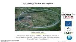
Future Circular Collider (FCC)
HTS coatings for FCC and beyond
*jgutierrez@icmab.es
PBC technology
minworkshop
: superconducting RF
Tuesday Sep 21, 2021
Slide24 – Potential
gain and ¿pitfalls?
of CCs below the GHz range3 – How we coat surfaces with CC2 – CCs vs Cu: Rs(H) in the GHz range 1 – Coated Conductors in a nutshellOutline
Slide34 – Potential
gain and
¿pitfalls? of CCs below the GHz range3 – How we coat surfaces with CC2 – CCs vs Cu: Rs(H) in the GHz range 1 – Coated Conductors in a nutshellOutline
Slide4Cu
~
20 mmAg ~ 2 mmREBCO HTS ~ 1 – 3 mmBuffers ~ 0.2 – 1 mmMetallic Substrate ~ 30 – 100 mm
Coated Conductors are commercially available
with different widths in
Km
length
T
c ≈ 91 KHc2
(4.2K) > 100 THirr (4.2K) > 60 T
Slide5CCs as low-impedance coating for the FCC-
hh
beam-screen chamberFCC working conditions:16 T, 40 – 60 K, 1 GHz & 25 A peakCCs offer excellent opportunities for high-energy physics
Slide6CCs as low-impedance coating for the FCC-
hh
beam-screen chamberP Be2QVGHigh Q T = 4.2K&High BeFCC working conditions:16
T,
40 – 60 K
, 1 GHz & 25 A peak
Higher than Cu Q-value RADES halsocopes
@ GHz
Opportunities for the BASE detector in the kHz – MHz range
CCs offer excellent opportunities for high-energy physics
CCs as low-impedance coating for
cold DM
axions
Slide7Z
s
characterization is done with a 8 GHz cavity Hakki-Coleman resonatorOperating in the mode Compatible with ICMAB cryostats: 25mm Ø bore 9 T magnet50mm Ø bore 16 T
magnet
Slide84 – Potential
gain and
¿pitfalls? of CCs below the GHz range3 – How we coat surfaces with CC2 – CCs vs Cu: Rs(H) in the GHz range 1 – Coated Conductors in a nutshellOutline
Slide9R
s of state-of-the-art CCs outperforms FCC Cu in the GHz range
FCC working conditions: 16 T, 40 – 60 K, 1 GHz & 25 A peakOutperform Cu Rs under FCC working conditionsWithstanding induced image currentsPreventing magnetic field disturbance Segmented REBCO-Cu hybrid coating
FCC
Cu
REBCO
T
= 50 K,
n
= 8 GHz
CCs as low-impedance coating for the FCC-
hh beam-screen chamberT. Puig et al, Supercond
. Sci. Technol. 32
(2019)
Slide10REBCO CCs support high-currents at high-magnetic fields
REBCO
is a HTS and a high-field superconductorFCC working conditions: 16 T, 40 – 60 K, 1 GHz & 25 A peakOutperform Cu Rs under FCC working conditionsWithstanding induced image currentsPreventing magnetic field disturbance
Segmented REBCO-Cu
hybrid coating
CCs as low-impedance coating for the FCC-
hh
beam-screen chamber
T. Puig et al, Supercond. Sci.
Technol. 32 (2019)
Slide11A segmented REBCO-Cu hybrid coating doesn’t disturb H and keeps good
R
s FCC working conditions: 16 T, 40 – 60 K, 1 GHz & 25 A peakOutperform Cu Rs under FCC working conditionsWithstanding induced image currentsPreventing magnetic field disturbance
Segmented REBCO-Cu
hybrid coating
CCs as low-impedance coating for the FCC-
hh beam-screen chamber
G.
Telles et al, to be submitted
(G. Telles @ EUCAS 2021, Field Quality and Surface resistance studies for the FCC beam screen. Materials IX, ID: 441)
Slide12The improvement in
R
s is higher at lower temperaturesT = 10 K, n = 8 GHzREBCO
T
= 50 K,
n
= 8 GHz
REBCO
DM
Axion detection cavities operate at 4.2K, further benefiting from REBCO
Slide134 – Potential
gain and
¿pitfalls? of CCs below the GHz range3 – How we coat surfaces with CC2 – CCs vs Cu: Rs(H) in the GHz range 1 – Coated Conductors in a nutshellOutline
Slide14Two-step delamination technique for large surface coatings with CCs
Attach
Welding
of CC
on top of a surface
Delamination
Mechanical peeling
Technology is easily scalable
A. Romanov & G.
Telles, to be submitted
Slide15Proof-of-concept:
CC coated RADES
haloscope shows a 50% in-field Q improvementCC coated Axion cavity Cu only Q(0T, 4.2K) ~ 80k Q(11T, 4.2K) ~ 60k vs Q(11T, 4.2K) ~ 40kCurvatureR9 mm
With some R&D efforts we made it
work
on curved surfaces
P
B
e2QVG
Slide16Proof-of-concept:
A R9 mm bending radius was a bit too much for the CC used
RADES haloscope CuT = 10 K, n = 8 GHz
CC coated Axion
cavity
Cu only
Q(0T, 4.2K) ~ 80k Q(11T, 4.2K)
~ 60k vs Q(11T, 4.2K) ~
40kRADES haloscope CC
REBCO
Curvature
R9 mm
P B
e
2QVG
Slide17Proof-of-concept:
Now we can coat R9 mm curvatures with nominal Rs valuesCC coated Axion cavity Cu only Q(0T, 4.2K) ~ 80k Q(11T, 4.2K) ~ 60k vs Q(11T, 4.2K) ~ 40kWe have learnt a big deal: In a near future we will be able to coat < R9 mm
RADES
haloscope
Cu
T
=
10 K, n
= 8 GHz
RADES haloscope CC
REBCO vs REBCO after R9 mm bent
Curvature
R9 mm
P Be2
QVG
Slide184 – Potential
gain and
¿pitfalls? of CCs below the GHz range3 – How we coat surfaces with CC2 – CCs vs Cu: Rs(H) in the GHz range 1 – Coated Conductors in a nutshellOutline
Slide19BASE opportunity: Enhanced Q and operating at higher
magnetic fields
BASE detector (exploded)OpportunitiesCoat the cavity with CCs Increase QMake a resonant REBCO coil Work at 100 MHz & high-Q (low-rf loss) in fields up to 10 T
n0
= 5
0
kHz- 200 kHz
Resonant
NbTi coil
Slide20A. Romanov
, et al. Scientific reports
10 (2020) GR model
At high magnetic fields, vortices dominate
Z
s
n
= 8 GHz
We can reconstruct
Zs and make predictions
The vortex resistivity is :
With
Fitting parameter
The
G-R
model shows excellent agreement with experiments
The
Gittleman
-Rosenblum model
Slide21The lower we go in frequency, the bigger the
R
s gain will be!But…Calatroni and Vaglio, IEEE Transactions on Applied Superconductivity, 27 (2017)CuREBCOFCC CuRRR100 CuRRR1000 Cufactor 1250 – 3000REBCO
R
s
REBCO
estimation with G-L model
T
= 4.2
K, n
= 100 MHz
CC’s Rs greatly outperforms that of Cu in the MHz range and below
Slide22We need to take into account the
effective
surface impedance of a multilayer systemStack
If
k
REBCO
t
REBCO
>> 1
ZStack ≈ ZREBCO
RF field penetration depth
Can we fulfil this condition < GHz range?
A. Romanov
, et al. Scientific reports 10 (2020)
Slide23It will be
advisable to characterize CCs
in the MHz range for :
In
the
MHz
REBCO @4.2K
n
0
= 40 – 60 GHz
rn = 5 – 30 mW
cmB
c2 = 80 – 120 TtREBCO ≈ 1.5 – 3 mmExperiment @ B = 10 T
kREBCOtREBCO = 3 – 15
If
kREBCOtREBCO >> 1
ZStack ≈ ZREBCO
our experience in the GHz range 3 – 15 is enough as not to see Zmetals
A. Romanov, et al. Scientific reports 10 (2020)
Slide24Conclusions
CCs are very appealing materials for high-frequency & high-field applications due to their low
Rs , high “Hc2” and high currents under magnetic field.REBCO CCs coatings provide a solution for the FCC-hh beam-screen chamber.We have demonstrated that cavities coated with REBCO have a higher Q-value in the GHz range under magnetic fields up to 11T. Potentially obtaining a factor >5 gain in Q factor as compared to Cu.In the MHz range (and below) REBCO CC can provide a factor >1000 improvement in Rs(H) as compared to Cu. An in-depth study of REBCO’s microwave response in this range is needed.
Slide25A word on Copper’s
R
s https://www.copper.org/resources/properties/cryogenic/
Slide26Copper
OFH
Copper
VP
Copper
Copper
OFH
Copper
VP
Copper
A word on Copper’s
R
s
Going beyond RRR
~
100 for Cu coatings is hard
Slide27Copper
OFH
Copper
VP
Copper
Copper
OFH
Copper
VP
Copper
A word on Copper’s
R
s
For accelerator components RRR
~
100 Cu coatings should be achievable
Slide28Copper
OFH
Copper
VP
Copper
A word on Copper’s
R
s
R
s
of state-of-the-art CCs outperforms
even OFH Cu
in the GHz range
T
= 10 K,
n = 8 GHz
Slide29The vortex resistivity is :
The Gittleman-Rosenblum model in a nutshell
Flux tube lattice
Equation of motion for
fluxons
:
Not considering thermal contributions
Assuming
T
he
Gittleman
-Rosenblum model
describes the microwave response of the mixed state
With
Fitting parameter