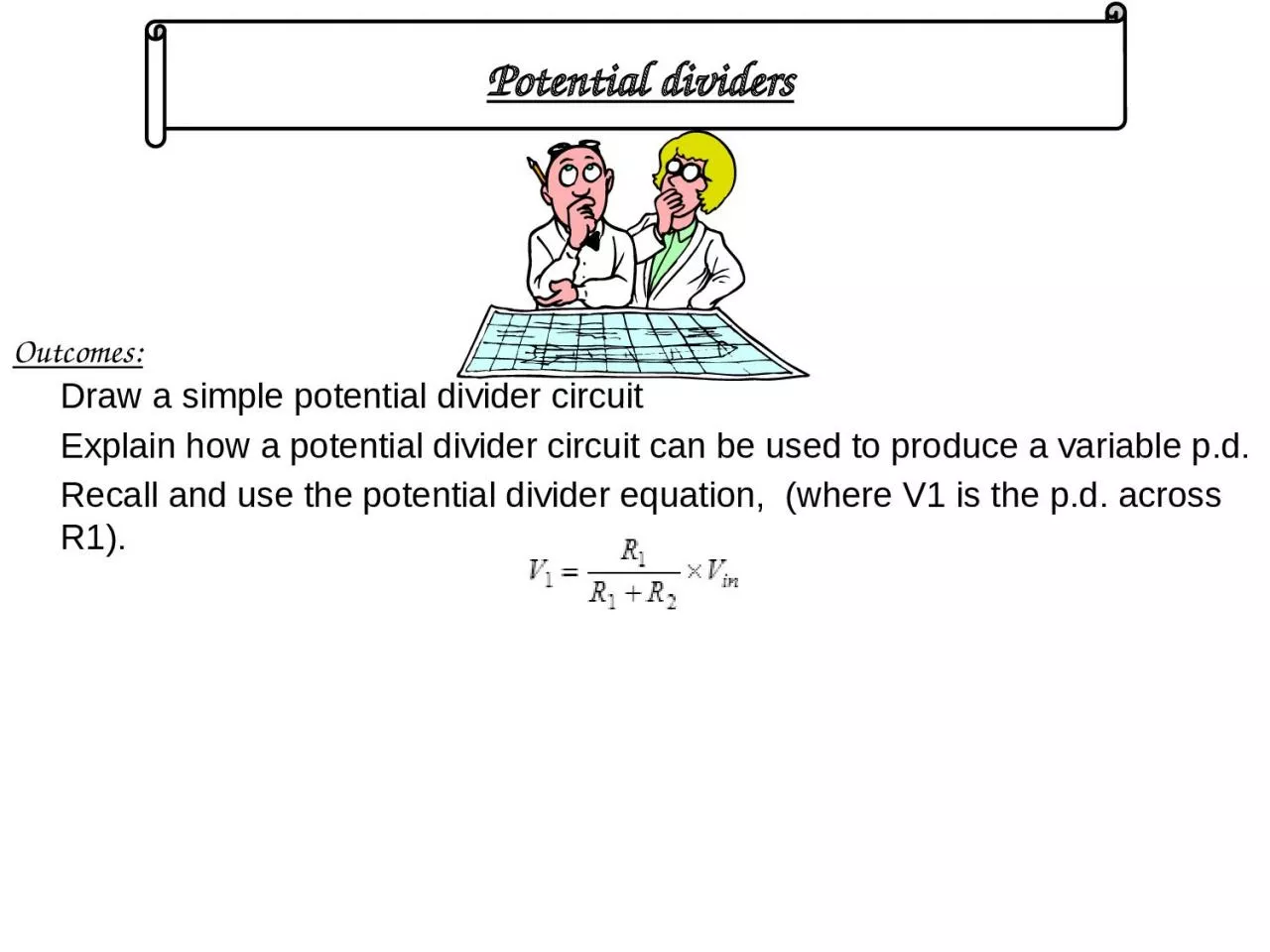
/
Outcomes: Draw a simple potential divider circuit Outcomes: Draw a simple potential divider circuit

Outcomes: Draw a simple potential divider circuit - PowerPoint Presentation

rosemary
rosemary . @rosemary
Follow
66 views
Uploaded On 2023-11-11

Outcomes: Draw a simple potential divider circuit - PPT Presentation

Explain how a potential divider circuit can be used to produce a variable pd Recall and use the potential divider equation where V1 is the pd across R1 Potential dividers Potential dividers ID: 1031224

circuit potential temperature resistance potential circuit resistance temperature increases divider supply vout voltage voltmeter dividers bulb ratio vin 120

Share:

Link:

Embed:

Download Presentation from below link

Download Presentation The PPT/PDF document "Outcomes: Draw a simple potential divide..." is the property of its rightful owner. Permission is granted to download and print the materials on this web site for personal, non-commercial use only, and to display it on your personal computer provided you do not modify the materials and that you retain all copyright notices contained in the materials. By downloading content from our website, you accept the terms of this agreement.


Presentation Transcript

1. Outcomes:Draw a simple potential divider circuitExplain how a potential divider circuit can be used to produce a variable p.d.Recall and use the potential divider equation, (where V1 is the p.d. across R1).Potential dividers

2. Potential dividersPotential dividers reduce voltage. Varying the ratio of a pair of resistors changes the output voltage of a circuit. 0 VVINR1R2VOUTVOUT will be a fraction of VIN. The magnitude of VOUT is dependent upon the ratio of the two resistors R1 and R2.VOUT0 V=R2VINR1 + R2×

3. What is the potential divider used for?To supply a pd which is fixed at any value between zero and the source pd (VIN)To supply a variable pdTo supply a pd which varies with physical conditions such light intensity or temperature

4. AVinVoutBCIR1R2If NO current is drawn through the output, thenby Ohm’s Lawand Vout = I x R2soThe voltage is divided in the same ratio as the resistorsTo supply a pd which is fixed at any value between zero and the source pd (VIN).212RRRVVinout+=

5. Example150VVout10k5k(i) Find Vout(ii) Find Vout if another 10 k resistor is connected across ABABSo RAB = 5 KOhmsVout = 75 VVoltskkkRRRVVinout10051010150212=+x=+x=Potential dividers

6. In the circuit shown, the battery has negligible internal resistance.(a) (i) If the emf of the battery = 9.0V, R1 = 120Ω and R2 = 60Ω, calculate the current I flowing in the circuit.(ii) Calculate the voltage reading on the voltmeter. (4 marks) (b) The circuit shown in the diagram acts as a potential divider. The circuit is now modified by replacing R1 with a temperature sensor, whose resistance decreases as the temperature increases.Explain whether the reading on the voltmeter increases or decreases as the temperature increases from a low value. (3 marks)RT = 120 W + 60 W = 180 WI = V / R = 9 / 180 = 0.05 AV = 9V x 60 120 + 60 = 3 VAs the temperature increases, the resistance across the temperature sensor drops. This makes the PD across it drop.So the PD on the voltmeter increases

7. Why doesn’t the bulb light?R1R23VR1R2The resistance of these two parts of the circuit is not the same!When the bulb is added, the resistance drops dramatically, reducing the PD across that partSo the bulb no longer lights!Test this by measuring the PD across section R1 for both circuitsThis is why Voltmeters need INFINITE RESISTANCE