
Hongfa Ding Zhou He Xiao Fang Dandi Zhang Lingda Xu Yonglin Zhi Zhou Jun Chang Liu L Li Wuhan National High Magnetic Field Center Huazhong University of Science and Technology ID: 1025515
Download Presentation The PPT/PDF document "Detection of Underground Utility Pole B..." is the property of its rightful owner. Permission is granted to download and print the materials on this web site for personal, non-commercial use only, and to display it on your personal computer provided you do not modify the materials and that you retain all copyright notices contained in the materials. By downloading content from our website, you accept the terms of this agreement.


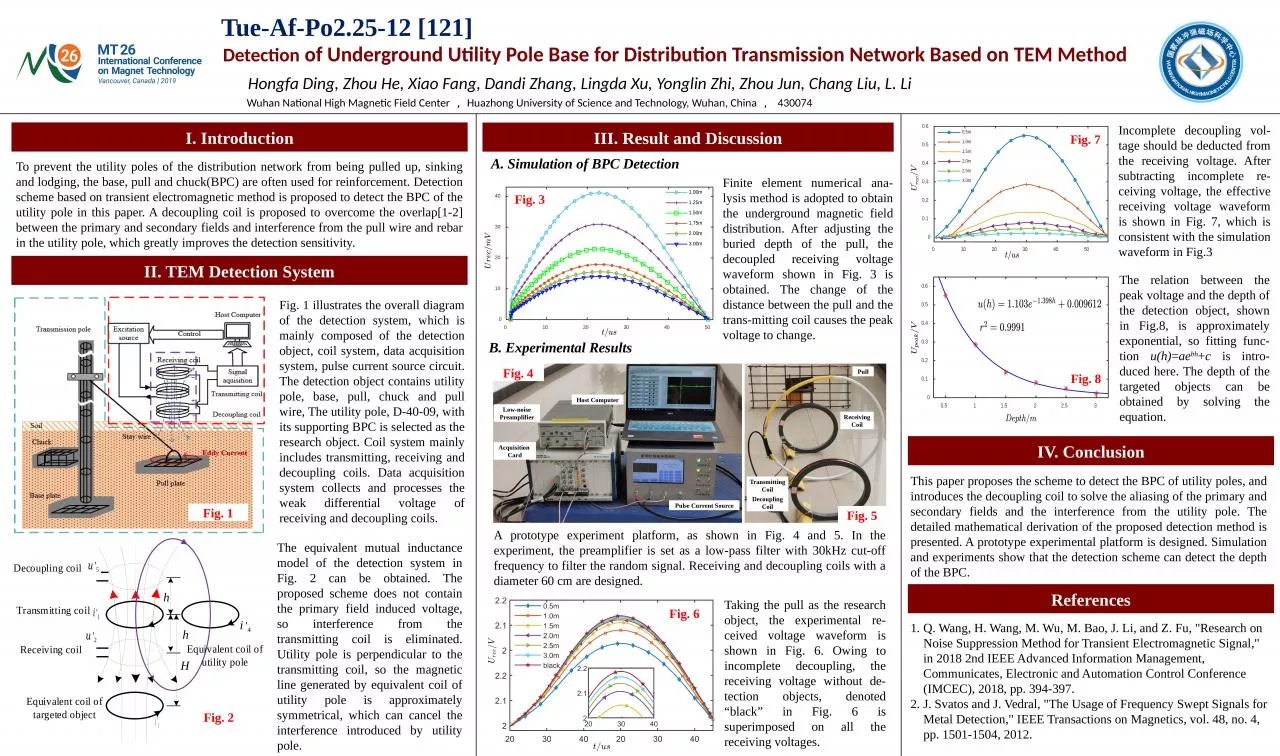
1. Detection of Underground Utility Pole Base for Distribution Transmission Network Based on TEM MethodHongfa Ding, Zhou He, Xiao Fang, Dandi Zhang, Lingda Xu, Yonglin Zhi, Zhou Jun, Chang Liu, L. LiWuhan National High Magnetic Field Center,Huazhong University of Science and Technology, Wuhan, China, 430074To prevent the utility poles of the distribution network from being pulled up, sinking and lodging, the base, pull and chuck(BPC) are often used for reinforcement. Detection scheme based on transient electromagnetic method is proposed to detect the BPC of the utility pole in this paper. A decoupling coil is proposed to overcome the overlap[1-2] between the primary and secondary fields and interference from the pull wire and rebar in the utility pole, which greatly improves the detection sensitivity.Fig. 1 illustrates the overall diagram of the detection system, which is mainly composed of the detection object, coil system, data acquisition system, pulse current source circuit. The detection object contains utility pole, base, pull, chuck and pull wire, The utility pole, D-40-09, with its supporting BPC is selected as the research object. Coil system mainly includes transmitting, receiving and decoupling coils. Data acquisition system collects and processes the weak differential voltage of receiving and decoupling coils.The equivalent mutual inductance model of the detection system in Fig. 2 can be obtained. The proposed scheme does not contain the primary field induced voltage, so interference from the transmitting coil is eliminated. Utility pole is perpendicular to the transmitting coil, so the magnetic line generated by equivalent coil of utility pole is approximately symmetrical, which can cancel the interference introduced by utility pole. 2) Strain evolutionQ. Wang, H. Wang, M. Wu, M. Bao, J. Li, and Z. Fu, "Research on Noise Suppression Method for Transient Electromagnetic Signal," in 2018 2nd IEEE Advanced Information Management, Communicates, Electronic and Automation Control Conference (IMCEC), 2018, pp. 394-397.J. Svatos and J. Vedral, "The Usage of Frequency Swept Signals for Metal Detection," IEEE Transactions on Magnetics, vol. 48, no. 4, pp. 1501-1504, 2012.Tue-Af-Po2.25-12 [121]I. IntroductionIII. Result and DiscussionII. TEM Detection SystemIV. ConclusionThis paper proposes the scheme to detect the BPC of utility poles, and introduces the decoupling coil to solve the aliasing of the primary and secondary fields and the interference from the utility pole. The detailed mathematical derivation of the proposed detection method is presented. A prototype experimental platform is designed. Simulation and experiments show that the detection scheme can detect the depth of the BPC.ReferencesFig. 1Host ComputerLow-noise PreamplifierAcquisition CardPulse Current SourceDecoupling CoilTransmitting CoilReceiving CoilPullFig. 6Fig. 8Fig. 2 Simulation of BPC DetectionFinite element numerical ana-lysis method is adopted to obtain the underground magnetic field distribution. After adjusting the buried depth of the pull, the decoupled receiving voltage waveform shown in Fig. 3 is obtained. The change of the distance between the pull and the trans-mitting coil causes the peak voltage to change. B. Experimental ResultsFig. 4A prototype experiment platform, as shown in Fig. 4 and 5. In the experiment, the preamplifier is set as a low-pass filter with 30kHz cut-off frequency to filter the random signal. Receiving and decoupling coils with a diameter 60 cm are designed. Fig. 5Taking the pull as the research object, the experimental re-ceived voltage waveform is shown in Fig. 6. Owing to incomplete decoupling, the receiving voltage without de-tection objects, denoted “black” in Fig. 6 is superimposed on all the receiving voltages. Fig. 7Fig. 3Incomplete decoupling vol-tage should be deducted from the receiving voltage. After subtracting incomplete re-ceiving voltage, the effective receiving voltage waveform is shown in Fig. 7, which is consistent with the simulation waveform in Fig.3The relation between the peak voltage and the depth of the detection object, shown in Fig.8, is approximately exponential, so fitting func-tion u(h)=aebh+c is intro-duced here. The depth of the targeted objects can be obtained by solving the equation.