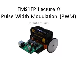
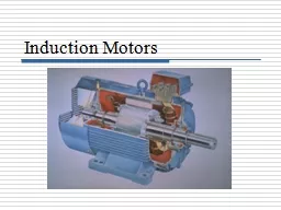
Submitted by Contents Project overview Block diagram Power supply Induction Motor Soft start of IM Optoisolator Schematic amp Working of the project Advantages Applications Future scope ID: 728610
Download Presentation The PPT/PDF document "SOFTSTART OF INDUCTION MOTOR BY AC-PWM" is the property of its rightful owner. Permission is granted to download and print the materials on this web site for personal, non-commercial use only, and to display it on your personal computer provided you do not modify the materials and that you retain all copyright notices contained in the materials. By downloading content from our website, you accept the terms of this agreement.
Slide1
SOFTSTART OF INDUCTION MOTOR BY AC-PWM
Submitted by:Slide2
Contents
Project overview
Block diagram
Power supply
Induction Motor
Soft start of IM
Opto-isolator
Schematic & Working of the project
Advantages
Applications
Future scope
ConclusionSlide3
Project overview
These Solid State Switches are phase controlled in a similar manner to a light dimmer, in that they are turned on for a part of each cycle.
The average voltage is controlled by varying the conduction angle of the switches.
Increasing the conduction angle will increase the average output voltage.
Controlling the average output voltage by means of solid state switches has a number of advantages. Slide4
Contd..One of the major advantages being the vast improvement in efficiency relative to the primary resistance starter, due to its low on state voltage of the solid state switches.Slide5
Block diagram
Refer
cdSlide6
Power supplySlide7
Contd..
The 230V AC supply is first stepped down to 12V AC using a step down transformer.
This is then converted to DC using bridge rectifier.
The AC ripples is filtered out by using a capacitor and given to the input pin of voltage regulator 7812.
At output pin of this regulator we get a constant 12V DC which is used for different ICs in this project. Slide8
Induction Motor
The single-phase induction machine is the most frequently used motor for refrigerators, washing machines, clocks, drills, compressors, pumps, and so forth.
The single-phase motor stator has a laminated iron core with two windings arranged perpendicularly.
One is the main and
The other is the auxiliary winding or starting winding Slide9Slide10
Contd..
This “single-phase” motors are truly two-phase machines.
The motor uses a squirrel cage rotor, which has a laminated iron core with slots.
Aluminum bars are molded on the slots and short-circuited at both ends with a ring.Slide11
IGBT
Applications
• AC motor speed control
• DC servo and robot drives
• Uninterruptible power supplies (UPS)
• Switched-mode and resonant-mode
power supplies
• DC choppers
Advantages
• Easy to mount (isolated mounting
hole)
• Reduces ass
In the normal "off" state, the device restricts current to the leakage current
When the gate-to-cathode voltage exceeds a certain threshold the device turns "on" and conducts current.Slide12
Soft starter
A soft starter is another form of reduced voltage starter for A.C. induction motors.
The soft starter is similar to a primary resistance or primary reactance starter in that it is in series with the supply to the motor.
The current into the starter equals the current out.
The soft starter employs solid state devices to control the current flow and therefore the voltage applied to the motor.
Soft starters are connected in series with the line voltage applied to the motor, or can be connected inside the delta loop of a delta connected motor, controlling the voltage applied to each winding.Slide13
Contd..Voltage control is achieved by means of solid state A.C. switches in series with one or more phases. These switches comprise either:
a.
Triac
b.
diode & SCR
c.
Two SCRsSlide14
Comparator
op amps & comparators look very similar
But a comparator gives a logic output indicating the relative potentials on its two inputs
An op amp amplifies the differential voltage between its two inputs – and is designed always to be used in closed-loop applicationsSlide15
Contd..
Potential dividers are connected to the inverting and non inverting inputs of the op-amp to give some voltage at these terminals.
Supply voltage is given to +V and –V is connected to ground.
The output of this comparator will be logic high (i.e., supply voltage) if the non-inverting terminal input is greater than the inverting terminal input of the comparator.
If the inverting terminal input is greater than the non-inverting terminal input then the output of the comparator will be logic low (i.e., gnd).Slide16
MICROCONTROLLER
It is a smaller computer
Has on-chip RAM, ROM, I/O ports...
RAM
ROM
I/O Port
Timer
Serial COM Port
Microcontroller
CPU
A single chipSlide17
INTERNAL STRUCTURE OF A MICRO CONTROLLER-AT89S52/51
CPU
On-chip RAM
On-chip ROM for program code
4 I/O Ports
Timer 0
Serial Port
OSC
Interrupt Control
External interrupts
Timer 1
Timer/Counter
Bus Control
TxD RxD
P0 P1 P2 P3
Address/Data
Counter InputsSlide18
Features of AT89S51/52
Compatible with MCS®-51 Products
8K Bytes of In-System Programmable (ISP) Flash Memory
Endurance: 10,000 Write/Erase Cycles
4.0V to 5.5V Operating Range
Fully Static Operation: 0 Hz to 33 MHz
256 x 8-bit Internal RAM
32 Programmable I/O Lines
Three 16-bit Timer/Counters
Eight Interrupt Sources
Full Duplex UART Serial Channel
Interrupt Recovery from Power-down Mode
Watchdog Timer
Dual Data PointerSlide19
Pin DescriptionSlide20
Optocoupler
Opto coupler is a 6 pin IC. It is a combination of 1 LED and a diac. Pin 5 is not generally used and when light falls on the diac then it switches ON the diac. Slide21
Contd..
When logic zero is given as input to the LED then the light doesn’t fall on diac so the diac is off means the current does not flow through the diac.
When logic 1 is given as input to the LED then light emitted by LED falls on diac so it starts conducting i.e., now there will be current flowing through the diac.Slide22
Working of project
Please Refer
cdSlide23Slide24