
Medium Access Control COS 463 Wireless Networks Lecture 4 Kyle Jamieson Enables exchange of atomic messages frames between end hosts on the same network Functions in L2 Determine start and end of bits and frames ID: 1002499
Download Presentation The PPT/PDF document "Link Layer I: Link Establishment," is the property of its rightful owner. Permission is granted to download and print the materials on this web site for personal, non-commercial use only, and to display it on your personal computer provided you do not modify the materials and that you retain all copyright notices contained in the materials. By downloading content from our website, you accept the terms of this agreement.


1. Link Layer I: Link Establishment,Medium Access ControlCOS 463: Wireless NetworksLecture 4Kyle Jamieson
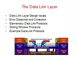
2. Enables exchange of atomic messages (frames) between end hosts on the same networkFunctions in L2:Determine start and end of bits and frames (framing)Establish link and deliver information reliablyToday: How Wi-Fi establishes a linkControl errorsIf needed, share the mediume.g., Shared-wire Ethernet, satellite uplink, Wi-FiToday: Medium access control to share the medium2Review: The Data Link Layer (L2)
3. Client moves out of AP 1’s coverage, into AP 2’s coverageOngoing TCP connections between client and server3Motivation: Link-Layer HandoffServerInternetAP 1AP 2Wired local-area networkClientHow to minimize TCP segment loss, TCP timeouts?TCP Connection
4. Notion of link-layer network: an Access Point (AP) and a set of connected clientsNamed by the service set identifier (SSID)APs generally drop data from clients, APs outside the setHow is the wireless link connection established?Discovery: Client detects presence of APAuthentication: Establish identity of AP, clientAssociation: Establish shared state between AP, client4Connecting to a Wi-Fi AP
5. How do clients find access points, and vice-versa?Access Points (APs) send short beacon frames every 100 millisecondsClients scan to discover the AP. Two ways:Passive scan: Switch channels, listen for beacons, wait, repeat on another channelActive scan: Send packets to probe for the AP’s presence51. Discovery
6. Don’t want to wait ca. 100 milliseconds for the next beacon from an AP that may or may not be presentActive scan protocol: On each channel:Client broadcasts probe request frameAP responds with probe response frame containing its SSID (network name), data rates supportedMultiple APs may respondClients chooses AP to continue with6Discovery: Active scan
7. AP establishes its identity to the client, and vice-versaA security problem!Open system authentication: Trivial, client sends authentication frame, AP responds “success”Shared key authentication: Configure both client and AP with a shared secret keyDoesn’t scale too wellEnterprise authentication: Use public key certificates, akin to web site authentication72. Authentication
8. The “commit” step that establishes shared AP-client stateClient sends association request frame to APAP sends association response frame to clientData now may flow, both to the AP (uplink) and to the client (downlink)83. Association
9. Back to the handoff example:9Initiating The Wi-Fi HandoffServerHow is the handoff initiated?Client tracks received signal strength from AP’s framesClient initiates handoff if and when signal strength falls below a threshold!!
10. Discovery stepSame as before10Wi-Fi Handoff Process: High-Level ViewServerAuthentication stepSame as beforeReassociation stepReplaces association step of the connection process discussed before
11. Reassociation Request: Client asks new AP to connectSupplies old AP identifierIAPP Move request: New AP asks for old AP’s stateIAPP Move response: Old AP supplies state to new APReassociation Response: “Commit” step, data may flow11Wi-Fi Handoff: ReassociationServerInter-Access Point Protocol (IAPP)1423
12. For how long is the client’s link-layer connection interrupted?This time duration is the reassociation latencyBeginning: frames get dropped from old APImprecise: Link-layer retransmissions recover some lossesEnd: Reassociation protocol completes with new APPrecise: Reassociation response message received12Reassociation: Latency
13. Conventional 802.11 reassociation takes ca. 40 to 100 msLong enough to trigger TCP duplicate ACKs, timeouts13802.11 Reassociation Performance[Mishra et al., 2003]
14. Wi-Fi standard 802.11r: Fast RoamingStore encryption keys on all APs in the networkSo no need for client to perform complete authentication process on reassociationWi-Fi Standard 802.11k: Assisted RoamingAP tells client a list of nearby other APs and their channelsSo no need for the client to scan14Improvements to Wi-Fi Handoff
15. Sharing by partitioning the mediumIntroduction, Time and Frequency divisionCode divisionContention-based sharingALOHAThe Ethernet15Medium Access Control
16. Medium access: The ProblemTwo questions:How should the shared medium be divided?Who gets to talk on a shared medium, and when?A medium access control (MAC) protocol specifies the above16
17. Medium access: Metrics of SuccessEfficiencyHigh throughput (bits/second successfully received)i.e. high utilization (throughput / raw channel rate)Fairness: All hosts with data to send should get a roughly equal share of the medium over timeLatency: Want to minimize the time a host waits before being granted permission to talk on the shared medium17
18. Physical Limitation: Finite speed of light18Geosynchronous Satellite (one way)100 ms30,000 kmMobileBase station300 m1 μsWi-Fi AP3−30 m10−100 nsFrom Princeton to...30 km100 μsTrenton300 km1 msWashington,D.C.Yellowstone3,000 km10 ms
19. Vastly Different Timescales,Same Medium Access Protocol!19100 ms30,000 km300 m1 μs3−30 m10−100 nsPacket Radio(ALOHA net)300 km1 ms3G/4G CellularDataWi-FiSatellite Communications
20. TDMA: Time Division Multiple AccessChannel time is divided fixed-period, repeating roundsEach user gets a fixed-length slot (packet time) in each round (unused slots are wasted)Out-of-band: Mechanism for allocating/de-allocating slotse.g.: six stations, only 1, 3, and 4 have data to send201341346-slotroundTime
21. FDMA: Frequency Division Multiple Access Channel spectrum divided into frequency bandsEach user gets a fixed frequency band (unused frequency slots are wasted)e.g.: six stations, only 1, 3, and 4 have data to send21frequency bandstimeFDM cable
22. AdvantagesUsers are guaranteed to be able to send bits, continuously (FDMA) or periodically (TDMA)DisadvantagesUnused time slots or frequency bands reduce channel utilizationAn out-of-band mechanism is needed to allocate slots or bands (which requires another channel)Guard bands or guard times reduce channel utilization22TDMA and FDMA: Considerations
23. Sharing by partitioning the mediumIntroduction, Time and Frequency divisionCode divisionContention-based sharingALOHAThe Ethernet23Medium Access Control
24. CDMA: Code Division Multiple AccessAll users transmit over the same frequencies, and at the same time:Allows multiple users to coexist and transmit simultaneously with no interference, in theoryIn practice: also performs wellSome cellular data networks have used CDMA24Alice(CDMA)CathyOkay!Bob
25. Let’s represent bits with two (binary) levels as follows:0 bit +1 level 1 bit −1 levelScenario: Alice receives data from Bob and Cathy:TDMA e.g.: Bob sends bits 101, Cathy sends 001:25Representing bits as binary levelsAliceCathyBobTDMA timeslots:+1−1timeTDMA timeslots:BobCathy
26. Assign each user a unique binary sequence of bits: codeCall each code bit a chip (convention)Call the code length MCDMA example:26CDMA: User codesAliceCathyBob+1−1timeCathy’s code ccathy+1−1Bob’s code cbob
27. Suppose Cathy alone sends message bits 001:27CDMA: Cathy SendingAliceCathyBob+1−1timeCathy’s messageCathy’s transmittedCDMA signal:Algorithm (CDMA encoding):For each message bit m:Send m × cuserccathy:+1−1L data bits M × L CDMA chipsBit rate: Factor of M slower
28. Let’s assume we have a way of:Synchronizing Cathy’s and Bob’s data bits in timeSynchronizing Cathy’s and Bob’s CDMA chips in timeEstimating and correcting the effect of the wireless channel between Cathy and Bob to Alice28CDMA: AssumptionsAliceCathyBob
29. 29What Alice HearsCathy’s transmittedCDMA signal:+1−1Bob’s transmittedCDMA signal:+1−1AliceCathyBobWhat Alice hears:+1−1+2−2Result: Neither Bob nor Cathy’s signal – interference!
30. 30Tool: Correlation+1−1Cathy’s code ccathy+1−1Bob’s code cbob+1−11. Multiply pointwise:Algorithm (correlation):Multiply two signals pointwise, across timeSum the result across timeNormalize (divide) by the signal lengthSum: 02. Sum across time Correlation: 03. Normalize (÷2)
31. 31Tool: Correlation+1−1Cathy’s code ccathy+1−11. Multiply pointwise:Algorithm (correlation):Multiply two signals pointwise, across timeSum the result across timeNormalize (divide) by the signal lengthSum: 22. Sum across time Correlation: 13. Normalize (÷2)Cathy’s code ccathy+1−1
32. 32Correlating Cathy’s Code withCathy’s CDMA transmission+1−1Cathy’s code ccathy+1−1CorrelationCathy’s transmission+1−1corrCathy sent: 0 0 1
33. 33Listening to CathyCathy’s transmission+1−1Bob’s transmission+1−1AliceCathyBobAlice hears a mixture+1−1+2−2+1−1Cathy’s code ccathy+1−1CorrelationcorrCathy sent: 0 0 1Zero-correlation with Bob’s code cancels Bob’s transmission from the mixture
34. Let’s generalize the Alice, Bob, Cathy scenario: N users, each user n has code , n = 1...N(m = 1...Code length M)Goal: Ensure cancellation of all other users when correlating against (each) one 34CDMA: How to choose codes?APUser 1User 2User 3User N...Zero mutual correlation condition: ★
35. Start with the Bob / Cathy code, write as rows in a matrixRecursive rule: given matrix M, form e.g. four users: 35Example CDMA code: Walsh Codes
36. CDMA advantages:Sending over entire channel frequency bandwidthSome parts of frequency band interfered? Okay!FDMA, TDMA, CDMA disadvantages: Rigid allocation of channel resources, requires advance coordination (frequency, time, code)Partitioning the channel reduced rateCan we have the best of both worlds, perhaps? 36CDMA: Considerations
37. Recall the two-user Walsh code , and recursive rule: given matrix M, form to double the number of users in the system.What’s the second user’s Walsh codein an eight-user CDMA system? 37Stretch Break with CDMA Calculation!
38. Sharing by partitioning the mediumIntroduction, Time and Frequency divisionCode divisionContention-based sharingUnslotted ALOHA, Slotted ALOHAThe Ethernet38Medium Access Control
39. Contention-based sharingWhen a station has a frame to send:Transmit at full channel data rate BNo a priori coordination among nodesTwo or more frames overlapping in time: collisionBoth frames lost, resulting in diminished throughputA random access MAC protocol specifies: How to detect collisionsHow to recover from collisions39
40. ALOHAnet: ContextNorm Abramson, 1970 at the University of HawaiiSeven campuses, on four islandsWanted to connect campus terminals and mainframeTelephone costs high, so built a packet radio network40
41. Unslotted ALOHASimplest possible medium access control: no control at all, anyone can just transmit a packet without delaySuppose: Chance packet begins in time interval Δt is λ × ΔtN senders in total, sending frames of time duration 1λ is the aggregate rate from all N sendersIndividual rate λ/N for each sender41
42. Unslotted ALOHA: PerformanceSuppose some node i is transmitting; let’s focus on i ’s frame42Others send in [t0−1, t0]: overlap i ’s frame start collisionOthers send in [t0, t0+1]: overlap i ’s frame end collisionOtherwise, no collision, node i ’s frame is deliveredTherefore, vulnerable period of length 2 around i ’s frameVulnerable period
43. Unslotted ALOHA: Performance43What’s the chance no one else sends in the vulnerable period (length 2)?Vulnerable period
44. Unslotted ALOHA: Utilization44Recall λ is the aggregate rate from all sendersSo, utilization = λ × Pr(no other transmission in 2) = λe−2λλUtilization1/2e ≈ 18%Too many collisions!Not sending fast enough
45. Slotted ALOHADivide time into slots of duration 1, synchronize so that nodes transmit only in a slotEach of N nodes transmits with probability p in each slotSo aggregate transmission rate λ = N × pAs before, if exactly one transmission in slot, can receive; if two or more in slot, no one can receive (collision)45...Node N
46. Slotted ALOHA: Utilization(N nodes, each transmits with probability p in each slot)What is the utilization as a function of aggregate rate λ = N × p?Pr[A node is successful in a slot] = p(1−p)N−1Pr[Success in a slot] = Np(1−p)N−146λ1/e ≈ 37%Utilization:λe-λ
47. ALOHA throughput: slotted versus unslottedUnslotted ALOHA: λe−2λSlotted ALOHA: λe−λ1/2e ≈ 18%1/e ≈ 36%Just by forcing nodes to transmit on slot boundaries, we double peak medium utilization!47
48. Sharing by partitioning the mediumIntroduction, Time and Frequency divisionCode divisionContention-based sharingUnslotted ALOHA, Slotted ALOHAThe Ethernet48Medium Access Control
49. How did the Ethernet get built?Bob Metcalfe, PhD student at Harvard in early 1970sWorking on protocols for the ARPAnetIntern at Xerox Palo Alto Research Center (PARC), 197349Needed a way to network ≈100 Alto workstations in-buildingAdapted ALOHA packet radioMetcalfe later founds 3Com, acquired by HP in April ’10 for USD $2.7 bn
50. The Ethernet: Physical designCoaxial cable, with propagation time τPropagation speed: 3/5 × speed of lightExperimental EthernetData rate: B = 3 Mbits/s, maximum length: 1000 mGoal: Any frame a station injects onto the coaxial cable reaches all other stations with high probabilityPropagation delay50
51. Collisions on the EthernetPacket of size N bits: N/B seconds on the wireOverlapping packets at B means signals sumNot time-synchronized: result is bit errors at BBut: C receives OK in this exampleABCZPropagation delay: τ seconds51Two Problems:Sender doesn’t know whether frame collided or notSender doesn’t know who received a colliding frame
52. Who gets to transmit, and when?Carrier Sense Multiple Accesswith Collision Detection (CSMA/CD)Begin the transmission procedure at any timeCarrier sensing: defer your transmission if you sense that another station is transmittingCollision detection: while sending, immediately abort your transmission if you detect another station transmitting52
53. When might a collision happen?Suppose Station A begins transmitting at time 0Assume that the packet lasts much longer than τAll stations sense transmission and defer by time τDon’t begin any new transmissionsABCZPropagation delay: τ seconds53
54. How long does a collision take to detect?Suppose Station A begins transmitting at time 0Worst case: Z begins transmitting just before time τJust before time 2τ, A and B hear Z’s transmission (hence detect collision)ABCZPropagation delay: τ seconds54
55. Collision detection and packet sizeIf packets take time 2τ, A will still be transmitting when Z’s packet arrives at A, so everyone will detect collisionSo Ethernet enforces a minimum packet size of 2τB bitsExperimental Ethernet: τ = 5 μs, B = 3 Mbits/s → 2τB = 30 bitsABCZPropagation delay: τ seconds, transmit rate B bits/sec55
56. Resolving collisionsUpon abort (carrier detect), station enters the backoff stateKey idea: the colliding stations all wait a random time before carrier sensing and transmitting againHow to pick the random waiting time? (Should be based on how stations have data to send)How to estimate the number of colliding stations?Goal: Engineer such that nodes will wait different amounts of time, carrier sense, and not collide56
57. Slotted Ethernet backoffBackoff time is slotted (like slotted ALOHA) and randomStation’s view of the where the first slot begins is at the end of the busy mediumRandom slot choice in contention window (CW)Goal: Choose slot time so that different nodes picking different slots CS and defer don’t collide57
58. OKBadPicking the length of a backoff slotConsider from the perspective of one packet at time tPackets before t−τ will cause packet to defer Packets after t+τ will not happen (why not?)Packets beginning within time τ apart will collideSo should we pick a backoff slot length of τ?OKττCause deferCS fail(Won’t happen)58
59. OKThe problem of clock skewNo! Slots are timed off the tail-end of the last packetTherefore, stations’ clocks differ by at most τSuppose we use a backoff slot length of τDifferent stations picking different slots may collide!OKττττΔStation B, slot 0Station A, slot 101201259
60. OKPicking slot time in presence of clock skewWant other station’s other slots to all be in “OK” regionThen, transmissions in different slots won’t collideWorst case clock skew: τSo, pick a slot time of τ + τ = 2τOK2τ2τ01201260τ
61. Binary Exponential BackoffBinary exponential backoff (BEB): double CW size on each consecutive collisionStations wait some number of slots chosen uniformly at random from CW = [0, 2m−1]Reset m ← 1 upon a successful transmissionFirst retransmit (m = 1): pick from [0, 1]Second retransmit (m = 2): pick from [0, 1, 2, 3]Observe: Stations transmitting new frames don’t take into account recent collisions, might transmit before stations in backoff61
62. CDMA wirelessNo interference between transmitting stationsAdaptation to varying numbers of users possible by changing codesReduced rate of individual transmissionsUnused codes waste overall capacityALOHA random accessStations can transmit using the entire medium, at full rate if aloneAlmost-instant adaptation to varying traffic loadsConcurrent transmissions result in collisions, reduced throughput62Comparing CDMA vs ALOHA random access
63. Monday, Tuesday PreceptsIntroduction to Lab 1Tuesday Topic:Link Layer II: Sharing the Medium,Wi-Fi Above the PHY63
64. Building the link: Framing bitsGoal: Move bits from one computer to anotherSender and receiver have independent clocksNo separate “clock signal” sent on the EthernetProblem: Agree on clock tick periodProblem: Agree on clock tick alignment (phase)64
65. Manchester encoding = Raw bit signal ⨁ Clock signalResult: “0” is a low-to-high transition; “1” is a high-to-lowTransition guaranteed on every bit, so receiver can bit-synchronize based on the encoding aloneDrawback: Halves data rate 65Manchester (phase) encodingRaw
66. Ethernet: Framing and Error DetectionFraming individual framesBeginning of frame determined by presence of carrierEnd of frame determined by absence of carrierPreamble: 101010 produces square wave (receiver sync)Destination address allows filtering at the link layerChecksum over whole packet payloadProtects against errors on coax but not against errors from tap itself (rely on higher layers; E2E argument)PreambleDestinationSourceDataChecksum8 bits8 bits16 bits4000 bits66
67. Carrier sensingMechanism: measure voltage on the wireBinary encoding: voltage depends on the dataManchester coding: constant average voltage67
68. Collision detectionPaper isn’t clear on this point (authors did have a patent in the filing process)Mechanism: monitor average voltage on cableManchester encoding means your transmission will have a predictable average voltage V0; others will increase V0Abort transmission immediately if Vmeasured > V0ABCZPropagation delay: τ seconds68