
This part of EN 10228 applies to four types of forgings classified according to their shape and method of 2 Normative references This part of EN 10228 incorporates by dated or undated reference p ID: 351266
Download Pdf The PPT/PDF document "may be used but should be agreed between..." is the property of its rightful owner. Permission is granted to download and print the materials on this web site for personal, non-commercial use only, and to display it on your personal computer provided you do not modify the materials and that you retain all copyright notices contained in the materials. By downloading content from our website, you accept the terms of this agreement.


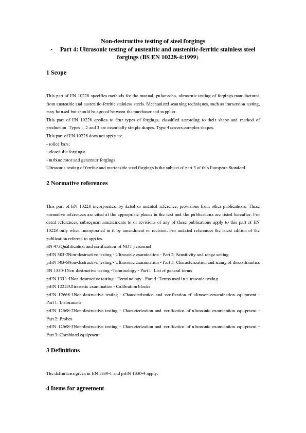
may be used but should be agreed between the purchaser and supplier. This part of EN 10228 applies to four types of forgings, classified according to their shape and method of 2 Normative references This part of EN 10228 incorporates, by dated or undated reference, provisions from other publications. These normative references are cited at the appropriate places in the text and the publications are listed hereafter. For prEN 583-5Non-destructive testing - Ultrasonic examination - Part 5: Characterization and sizing of discontinuities EN 1330-1Non destructive testing -Terminology - Part 1: List of general terms prEN 1330-4Non destructive testing - Terminology - Part 4: Terms used in ultrasonic testing prEN 12668-3Non-destructive testing - Characterization and verification of ultrasonic examination equipment - Part 3: Combined equipment 3 Definitions The definitions given in EN 1330-1 and prEN 1330-4 apply. 4 Items for agreement The following aspects concerning ultrasonic testing shall be agreed between the purchaser and supplier at the time of the enquiry or order: a) the volume(s) to be tested and whether grid scanning coverage or 100% scanning coverage is required (see clause 12); b) whether near surface examination is required (see 7.2.6); c) the quality class required, or the quality classes and the zones to which they apply (see clause 14); d) whether any special scanning coverage, equipment or couplant is required in addition to that detailed in clauses 7 and 12; e) the scanning technique to be used if not manual (see clause 1); f) the sizing techniques to be used for extended discontinuities (see clause 15); g) the technique(s) to be used for setting sensitivity (see clause 11); h) whether the test is to be conducted in the presence of the purchaser or his representative; i) whether a written procedure shall be submitted for approval by the purchaser (see clause 5); j) whether examination by shear wave probes is required (see 11.3); k) the remaining examination requirements for complex forgings (type 4) (see 12.2). 5 Written procedure Ultrasonic testing shall be performed in accordance with a written procedure. Where specified in the enquiry or order, the written procedure shall be submitted to the purchaser for approval prior to testing. This written procedure shall be in the form of: a product specification; or a procedure written specifically for the application; or this part of EN 10228 may be used if it is accompanied by examination details specific The written procedure shall contain the following details as a minimum requirement: a) description of the item to be examined; b) reference documents; c) qualification and certification of examination personnel; d) stage of manufacture at which the examination is carried out; e) examination zones specified in terms of the applicable quality classes; f) preparation of scanning surfaces; g) couplant; h) description of examination equipment; i) calibration and settings; j) scanning plan; k) description and sequence of examination operations; l) recording levels; m) characterization of discontinuities; n) acceptance criteria; o) examination report. 6 Personnel qualification If near-surface examination is required, then twin crystal probes shall be used. 7.3 Calibration blocks Calibration blocks shall conform to the requirements detailed in prEN 12223. 7.4 Reference blocks Reference blocks shall be used when sensitivity is to be established by the distance amplitude curve (DAC) technique and/or when defects are to be sized in terms of amplitude relative to reference reflectors by the DAC technique. The surface condition of the reference block shall be representative of the surface condition of the part to be examined. Unless otherwise specified, the reference block shall contain at least three reflectors covering the entire depth range under examination. The reference block shall be manufactured from one of the following: a) an excess length of the part to be examined, or b) a part of the same material and with the same heat treatment condition as the part to be examined; or c) a part having similar acoustic properties to the part to be examined. Reference blocks shall not be used for the distance gain size (DGS) technique other than for checking the accuracy of a particular DGS diagram. NOTE Different sizes of reflectors from those detailed in Tables 5 and 6 may be used as long as the test sensitivity is corrected accordingly. 7.5 Couplant The same type of couplant shall be used for calibration, setting sensitivity, scanning and defect assessment. NOTE Examples of suitable couplants are: water (with or without corrosion inhibitor or softener), grease, oil, glycerol and water-cellulose paste. After examination, couplant shall be removed if its presence could adversely affect later manufacturing or inspection operations or the integrity of the component. 8 Routine calibration and checking The combined equipment (flaw detector and probes) shall be calibrated and checked in accordance with the requirements detailed in prEN 12668-3. 9 Stage of manufacture Ultrasonic testing shall be performed after the final quality heat treatment or at the latest stage of manufacture at which the required ultrasonic coverage can be achieved. b) distance gain size (DGS) technique. The procedure to be used in each case shall be in accordance with prEN 583-2. 11.3 Shear-wave probes (see 4j) For shear-wave probes, one of the following techniques shall be used to establish sensitivity for scanning: a) DAC technique using 3 mm diameter side-drilled holes; b) DGS technique. The procedure to be used in each case shall be as detailed in prEN 583-2. The DAC and DGS techniques shall not be compared for shear wave probes. 11.4 Repeat inspection Where repeat inspection is performed, the same method of establishing sensitivity (DAC or DGS) shall be used as was initially used. 12 Scanning 12.1 General Scanning shall be performed using the manual contact pulse-echo techniques. The minimum scanning coverage required is dictated by the type of forging and whether grid scanning coverage or 100% scanning coverage has been specified in the enquiry or order. Table 1 classifies four types of forging according to their shapes and method of production. Scanning coverage of forging types 1, 2 and 3 with normal probes shall be as given in Table 2. Scanning coverage with shear-wave probes for forging types 3a and 3b which have outside diameter to inside diameter ratio of less than 1,6:1 shall be as given in Table 3. The effective depth of circumferentially orientated shear wave scans is limited by the probe angle and the forging diameter (see annex A). 12.2 Complex forgings For complex shaped forgings or complex shaped parts of forgings (type 4) and small diameter forgings, examination shall include, as a minimum, the required probe angles, scanning directions and extent of scanning coverage (grid or 100%). The remaining requirements shall be agreed between purchaser and supplier (see 4k). 12.3 Grid scanning coverage Grid scanning shall be performed with the probe or probes traversed along the grid lines defined in Tables 2 and 3. 3b Expanded Hollow cylindrical shapes, e.g. rings, flanges, rims Circular laminating 4 All forgings or parts of forgings with complex shape At the manufacturer' s discretion 1)Type 1 forgings may incorporate bores of small diameter relative to the major dimensions 2)Type 2 forgings may eventually be drilled (e.g. binding discs) Table 2 : Scanning coverage with normal probes Grid Scanning 100% scanning1)2) Diameter, D Scan lines D 200 500 1000 2 at 90° 3 at 60° 4 at 45° Scan 100% around at least 180°of cylindrical surface 1 1b Scan along the lines of a square-link grid on two perpendicular surfacesScan 100% on two perpendicular surfaces 2 Scan along the lines of a square-link grid around 360°on the cylindrical surface and one Scan 100% around at least 180°on the cylindrical surface and 100% of one lateral surface 3 Scan along the lines of a square-link grid around 360°on the outer cylindrical surfaceScan 100% around 360°on the outer cylindrical surface 13.1 Classification of indications Where practicable classification of indications according to their echodynamic pattern shall be made by scanning from a minimum of two mutually perpendicular directions. a) Pattern 1As the probe is moved, the A-scan display shows a single sharp indication rising smoothly in amplitude to a maximum and then falling smoothly to zero (see Figure 1a). This A-scan display in combination with the echodynamic pattern in Figure 1b obtained from the side-drilled holes used to plot the beam profile, corresponds to discontinuity dimensions smaller than or equal to the -6 db beam profile. Figure 1a: A-scan presentation (At typical probe position) Figure 1b: Echodynamic pattern (Variation in signal amplitude as probe is moveFigure 1 : Pattern 1 A-scan presentation and echo envelope presentationb) Pattern 2 As the probe is moved, the A-scan display shows a single sharp indication rising smoothly in amplitude to a maximum and then falling smoothly to zero (see Figure 2a). This A-scan display in combination with the echodynamic pattern in Figure 2b obtained from the side-drilled holes used to plot the beam profile, corresponds to discontinuity dimensions greater than the to -6 dB beam profile. Figure 3c: Isolated point discontinuities�, d 40mm) Figure 3d: Grouped point discontinuities Dp, d 40mm) Symbols used: 1: Conventional outline of -6 dB discontinuity : Width of beam at depth of discontinuity d: Distance between two discontinuities L: Conventional length of -6 dB discontinuity 14 Recording levels and acceptance criteria Several quality classes may be applied to a forging or to parts of a forging. The applicable quality class(es) shall be agreed between the purchaser and supplier. Table 4 details recording levels and acceptance criteria which shall be applied to three quality classes for normal probes. Tables 5 and 6 detail recording levels and acceptance criteria which shall be applied for shear waves. Table 4: Quality classes recording and acceptance criteria for normal probes 1) Acceptance criteria for Forging thickn ess Recording level Isolated discontinuities d Extended or grouped discontinuities Quality class 1 t�75 5 8 5 �28 u 0;t3 2 50 400&#x t00;d 600&#x t00;d Indication with a 80reduction of backwall echo Indication with a total loss of backwall echo. A total loss of backwall echo is to be considered when its amplitude becomes less than 5% of its initial value measured near the indication or less than or equal to grass 1)Reflector diameter shall not be interpreted as representing the dimension of the discontinuity which cau = Equivalent diameter of flat-bottomed hole. Table 5: Recording and acceptance criteria for shear waveprobes for DGS techniques Acceptance criteria for Forging thickness t Recording level d Isolated discontinuities mm Extended or grouped discontinuities mm t�75 3 5 3 �75 5 8 5 � 8 All tests shall be the subject of a written report which shall include the following information as a minimum requirement: a) name of supplier; b) order number; c) identification of forging(s) under examination; d) scope of examination: examination zones and applicable quality classes; e) stage of manufacture at which ultrasonic testing was performed; f) surface condition; g) equipment used h) technique(s) used to set sensitivity; i) reference to this standard and, if applicable, reference to the written procedure used; j) results of examination: location, classification and amplitude (in terms of FBH-equivalent diameter, or in percent of SDH) of all discontinuities exceeding the appropriate recording level; k) details of any restrictions to the required scanning coverage and if applicable the extent of the near surface zone; l) date of examination; m) name, qualification and signature of operator. Annex A (informative) Maximum testable depth for circumferential shear wave scans Maximum testable depths (see Figure A.1) for circumferential shear-wave scans, for various probe angles and outside radii, are given in Table A.1. Figure A.1 - Maximum testable depth for circumferential shear wave scans Probe angle X Maximum test depth, M Beam path range, D 70° 0.06R 0.34R