/
nt Property of slope with nt Property of slope with

nt Property of slope with - PDF document

luanne-stotts
luanne-stotts . @luanne-stotts
Follow
421 views
Uploaded On 2015-09-18

nt Property of slope with - PPT Presentation

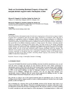
Shuyan Ji Yingmin Li Jun Han Liping Liu Jinyin Cui College of Civil Engirsity Chongqing China Shuyan Ji Yingmin Li Jun Han Liping Liu Jinyin CuiKey Laboratory of New Technology for Construct ID: 132501

Shuyan Yingmin Jun

Share:

Link:

Embed:

Download Presentation from below link

Download Pdf The PPT/PDF document "nt Property of slope with" is the property of its rightful owner. Permission is granted to download and print the materials on this web site for personal, non-commercial use only, and to display it on your personal computer provided you do not modify the materials and that you retain all copyright notices contained in the materials. By downloading content from our website, you accept the terms of this agreement.


Presentation Transcript

nt Property of slope with Shuyan Ji, Yingmin Li, Jun Han, Liping Liu, Jinyin Cui College of Civil Engirsity, Chongqing, China Shuyan Ji, Yingmin Li, Jun Han, Liping Liu, Jinyin CuiKey Laboratory of New Technology for Construction of Cities in Mountain Area(Chongqing in the fields of industrial, building, ships, etc. In this sense, research on overturning problems is Figure 1.1. Schematic diagram of Structure with unequal number of stories due to sloped ground As a special form of structures, the overturning resistant capability of structures on slope is relatively less than normal structures. At present, although the relevant publications are few, the overturning problem of structures on slope is still an unavoidable question that requires an answer. This paper investigates the overturning problem of structures on slope. Analysis models of structures on slope and relevant parameter settings are studied. Analyses of the base stress distribution under horizontal earthquake action is conducted. By comparing with normal structures, this paper also studies the influence law of story number and bay number on the seismic overturning resistant capability of 2. STRUCTURAL MODEL AND PARAMETER SETTING FOR INTERACTION OF SOIL AND STRUCTURE ON SLOPE According to the relationship between the structure on slope and the surrounding soil, the document provided three types of structures on slope as depicted in Figure 2.1. The first type is called the mutually separated structure, in which the dropped stories and the surrounding soil are separated by the retaining wall. The second type is called the mutually connected structure without anchors, in which they are connected without anchors and the connecting part acts as not only the retaining wall but also part of the structure. The third type is called the mutually connected structure with anchors, in which their connection is strengthened by anchors to ensure the stability of the surrounding soil. mutually separated structure mutually connected mutually connected structure without anchors structure with anchors Figure 2.1. Structure on slope and surrounding soil connections The second and third types in which the structure on slope and the surrounding soil are connected are collectively referred to as the mutually connected structure in the sense that both types are the same when the anchors lose their bearing capacity. With this in mind, structure on slope as shown in Figure2.1 can be also divided to two types: (a) the mutually separated structure and (b) the mutually connected structure, as shown in Figure 2.2. It is conservative to neglect the impact of the surrounding soil. All the analyzed models of this section are planar structures. mutually separated structure (b) mutually connected structure Figure 2.2. Analysis models Table.2.1 Seismic angle As shown in Figure 2.2, the analysis model is not the actual size of the structure but the reduced size. This spatial reduction is done to save computational cost without influence on the investigation of the base stress distribution under horizontal loads. If the height of the structure on slope is measured from the under ground and the width is considered to be that of the upper structure, the height-width ratio is 3. The height of the lower structure is 1/5 of the total height, and the height of the base is 1/15 of the total height of the structure on slope. The parameters of bedrock and structure are listed in Table 2.1. In the analysis, the planar 42 element was adopted. The D-P criterion was used to simulate the nonlinear behavior of the soil. In addition, contact element was set at the boundary between the base and the soil and the friction coefficient was assumed to be 0.2. Lateral loads exhibit inversed triangular distribution, considering both positive and negative loads respectively. 3.BASE STRESS DISTRIBUTION OF STRUCTURE ON SLOPE WITH SHALLOW FOUNDATION UNDER OVERTURNING LOADS First, the mutually separated structure is considered. The base stress distribution of the model under its dead load is shown in Figure 3.1. The base stress of the two bases of the structure on slope exhibits an even distribution under the vertical loads. But the stress of the under base is higher than the upper one due to the increase of the weight of the dropped part. In the analysis, different slope ratios of the inversed triangular distribution of the lateral force are considered, i.e., 1000, 1500, 2000,4500,5000,6500 (unit: kN/m). Under the gradually increasing overturning moment, the base stress distributions of the mutually separated structure are shown in Figure 3.2. Figure 3.1. Base stress under the gravity loads Loads with a slop of 1000 Loads with a slop of 2000 Loads with a slop of 3000 Loads with a slop of 4000 Figure 3.2. Base stress under forward direction loads According to the base stress distribution in Figure 3.2., it is noticed that the base stress of the mutually separated structure changes from trapezoidal to triangular distribution with the gradual increase of positive overturning moment; then separation occurs between the upper base ground and the soil and the zero-stress zone appears on the upper base bottom; along this increase the zero-stress subsequently occurs on the lower base bottom and the maximum stress increases simultaneously. The base stress distribution of the mutually separated structure under the inversely increasing moment of overturning is shown in Figure 3.3. Loads with a slop of 1000 Loads with a slop of 2000 Loads with a slop of 3000 Loads with a slop of 4000 Loads with a slop of 4090 Figure 3.3. Base stress under reversed direction loads In Figure 3.3., it is found that the base stress distribution of the mutually separated structure also changes under the gradually increasing positive overturning moment. The pressure on the upper base ground exhibits the transition from the trapezoidal distribution to the triangular distribution. Then the zero-stress zone occurs after the separation between the upper base ground and the soil is developed. When the overturning loads continue to increase, zero-stress zone occurs one after another, with the maximum compressive stress value increased constantly. Compared with base stress distribution under the same loads in both directions, the negative compression zone is greater than the positive one, i.e., the capability of the mutually connected structure to resist the negative overturning moment is relatively greater. The base stress distribution law of the mutually connected structure under the gradually increasing horizontal loads in both positive and negative directions is the same as that of the mutually separated structure. Therefore it is not discussed in the paper. Similarly, the capability of the mutually connected structure to resist the negative overturning moment is also relatively greater. 4. OVERALL OVERTURNING RESISTANT CAPACITY ANALYSIS OF STRUCTURE ON SLOPE UNDER EARTHQUAKE ACTION 4.1 Comparison of seismic overturning resistant capacity of structure on slope and normal structure Three planar frames shown in Figure 4.1 were used for the comparison. The beam sections, column sections, vertical loads and the seismic action parameters were assumed to be the same among these three frames. The three model structures have the same bay number. Model B has the same upper story number as model A. Models B and C have the same overall story numbers. Model A Model B Model C Figure 4.1. Calculation model Given the same overturning loads, e.g. a concentrated force of 1000KN applied at the top of the structures, the reaction forces of the structures are listed in Table 4.1. It is noted that the overturning stability of the structure on slope, i.e. model B is more disadvantageous than the two normal structures. Table 4.1 Overturning calculation under horizontal single forces (Unit: KN,m ) Model A Model B Model c Overturning moment 24000.00 36000.00 36000.00 Resistant overturning moment 145651.50 162974.43 219096.90 Safety factor 6.07 4.53 6.09 When checking the overturning resistant stability of the structure under the earthquake action, only the first three vibration modes were considered and the modal mass participation factors of the structures are satisfied. It is found that the overturning resistant moment of the structure on slop under the earthquake action increases significantly for model A, while smaller than that of Model C. Therefore the safety factor of the structure on slope is lower, and its overturning resistant stability is disadvantageous compared with the other two models. Table 4.2Overturning calculation under seismic action(Unit: KN,m ) Model A Model B Model C Overturning moment 10994.34 19246.24 16418.02 Overturning resistant moment 145651.50 162974.43 219096.90 Safety factor 13.25 8.47 13.34 Comparing the equivalent floor horizontal forces of the three models corresponding to the first three vibration modes under earthquake action as shown in Figure 4.2., the equivalent floor horizontal forces of the upper structure in Model B under the first and second vibration modes are close to those in model A. The overturning resistant moment increases due to the increase of the overturning force arm compared to model A. As far as model B and model C are concerned, the equivalent floor horizontal force of the upper structure of Model B is relatively lower and therefore its overturning moment is relatively higher. (a) Model 1 (b) Model 2 (c) Model 3 Figure 4.2. Horizontal equivalent static forces to story 4.2 Analysis of seismic overturning resistant capacity of structure on slopeThe seismic overturning resistant capacity of structure on slope is relatively lower than that of the normal structure of the same height, whether the height is measured from the upper ground or from the lower ground. In order to further study the seismic overturning resistant capacity, three slope structures on slope with different story numbers and different bay numbers were analyzed. The analyzed models are as shown in Figure 4.3, which are planar frame structures with total height of 45m, story height of 3m, total bay number of 6 and bay span of 6m. The beam and column cross sections are 300mm600mm and 700 mm700 mm. The uniform dead and live loads are 27kN/m and 12kN/m. The seismic fortification intensity level is assumed to be 8 degree with the peak ground acceleration of 0.2g according to Chinese Seismic Design Code. The design level earthquake is assumed near fault. And the site classification is II. In addition, the additional by the infill walls of the frames was considered by only accounting for 70% of the calculated structural natural period. The modal response spectrum method was adopted to calculate the earthquake action, and the CQC combination of the overturning moment in each vibration mode was conducted to calculate the overturning moment under the earthquake action. Meanwhile, the impact of second-order effect was included in the analysis as well as the influence of vertical loads on the overturning force arm caused by the horizontal deformation. Firstly, the normal structure was analyzed. It was obtained that the overturning moment of the structure was 37004kN.m, the overturning resistant moment of the structure was 299671kN.m and the safety factor of the structure’s overturning resistant capacity is 8.09. And then the structural models with the different number of slope storey number and slope bay numbers were analyzed. Their seismic overturning moments, overturning resistant capacity and safety factors were plotted in Figure4.4. According to the horizontal seismic force distribution in the different modes as shown in Figure 4.2., it is noticed that: if the story number is identical, the equivalent horizontal floor force of the structure under the earthquake action decreases with the increase of dropped bay number; and the horizontal force of the upper story under the fundamental mode increases with the increase of the story number. But the arm of horizontal force remains constant, which results in the increase of the overturning moment of the structure on slope. normal structure two stories difference and three stories difference and three dropped bays four dropped bays Figure4.3. Calculation model (a) the overturning moment (b) the resistant overturning moment Figure4.4. bending moment of overturning and overturning-resistant Figure 4.5. factor of safety against overturning Obviously, with the increase of the dropped story number, the overturning moment of the structure increases while the overturning resistant moment decreases, resulting in the decrease of the final overall overturning resistant safety factor. However, with the increase of the dropped bay number, the overturning moment of the structure decreases while the overturning resistant moment increases, resulting in the increase of the final overall overturning resistant safety factor. With the increase of the dropped story number and the decrease of the dropped bay number, the overall anti-overturning stability is lower. 5. CONCLUSION This paper suggests the analysis models and parameter settings for the interaction simulation between the structure on slope and the soil. And it also studies the base shear distribution of the mutually separated structure on slope under gradually increasing positive or negative overturning moment. Finally, by comparison with the normal structure, the paper investigates the variation principle of the seismic overturning resistant capacity of the structure on slope with respect to storey number and bay number. The following conclusions are made: (1) Compared with the normal structure, the safety factor for anti-overturning and the anti-overturning stability of the structure on slope are decreased. (2)The overall seismic overturning resistant capacity decreases with the increase of the difference of unequal story numbers and the decrease of the bay number. Therefore it is suggested that the overall seismic overturning resistant capacity of the structure on slope be checked directly. ACKNOWLEDGEMENT This research is supported by the Natural Science Foundation Project of Chongqing CSTCJJA30006, Natural Science Foundation Project of Chongqing CSTC (2010GGB104) and Foundation for Sci & Tech Research Project of Chongqing Construction (2011-No.2-85) . REFERENCES Liping Wang.(2010),Design ground motion input and control method of lateral stiffness for building structures on the slope, Chongqing University,China. Yingmin Li and Liping Liu. (2008),Building damage and consideration caused by the Wenchuan,Chongqing University Press. Yigong Wang and Youfa,Yang. (2005). A study on dynamic interaction problem of multistory frames located at hillside sites with different slopes. World Earthquake Engineering21:3,88-93. Youfa Yang.Yigong Wang.Study on dynamic interaction problem of frame on inclined rock-base.Earthquake Engineering and Engineering Vibration25:2,177-182. Zhiwei Shan.(2008).Study on the Seismic Performance of Step-Terrace Structure. Chongqing University,China. Bin Long.(2010).Study on Several Problems Related to the Seismic Design of Structure Supported by Foundations with Different Locations. Chongqing University,China. Gang Wang, Yang Chen and Jianmin Zhang.(2006). Finite element method for analyzing overturn stability of large cylindrical structures.Rock-soil Mechanics27:2,238 -241. Wenhua Hao.ANSYS.(2005),Civil engineering application examples, China's Water Conservancy And Hydropower Press. Xin min Wang.(2007),ANSYS numerical analysis of engineering structures,China Communications Press. Yu Zhuo.(2001). The overturning Stability checking of high-rise buildings. Guangdong Civil Engineering & Construction. 2001:1,27-28. Huating Ye. (2008).Discuss the High-level Architecture Structure General Overturn Checking. Overseas Architecture.2008:6,125-126. MOHURD.(2010). Technical specification for concrete structures of tall building. China Architecture and Building Press. MOHURD. (2010). Code for Seismic Design of China (GB 50011-2010), China Architecture and Building Yuxian Hu. (2006). Earthquake Engineering, Seismological Press, Beijing, China. MOHURD.(2010). Code for design of building foundation. China Architecture and Building Press.