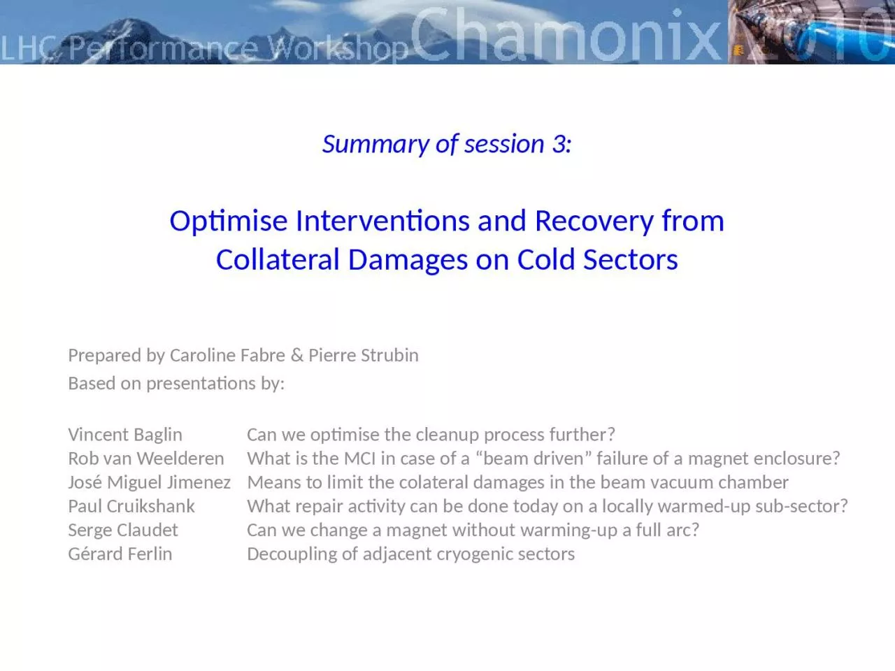
/
Summary of session 3: Optimise Interventions and Recovery from Summary of session 3: Optimise Interventions and Recovery from

Summary of session 3: Optimise Interventions and Recovery from - PowerPoint Presentation

SmoochieBoochie
SmoochieBoochie . @SmoochieBoochie
Follow
342 views
Uploaded On 2022-07-28

Summary of session 3: Optimise Interventions and Recovery from - PPT Presentation

Collateral Damages on Cold Sectors Prepared by Caroline Fabre amp Pierre Strubin Based on presentations by Vincent Baglin Can we optimise the cleanup process further Rob van ID: 930753

sector beam summary 2010 beam sector 2010 summary vacuum session february cold 2010chamonix warm magnet line adjacent arc full

Share:

Link:

Embed:

Download Presentation from below link

Download Presentation The PPT/PDF document "Summary of session 3: Optimise Intervent..." is the property of its rightful owner. Permission is granted to download and print the materials on this web site for personal, non-commercial use only, and to display it on your personal computer provided you do not modify the materials and that you retain all copyright notices contained in the materials. By downloading content from our website, you accept the terms of this agreement.


Presentation Transcript

Slide1

Summary of session 3:Optimise Interventions and Recovery fromCollateral Damages on Cold Sectors

Prepared by Caroline Fabre & Pierre StrubinBased on presentations by: Vincent Baglin Can we optimise the cleanup process further? Rob van Weelderen What is the MCI in case of a “beam driven” failure of a magnet enclosure? José Miguel Jimenez Means to limit the colateral damages in the beam vacuum chamber Paul Cruikshank What repair activity can be done today on a locally warmed-up sub-sector? Serge Claudet Can we change a magnet without warming-up a full arc? Gérard Ferlin Decoupling of adjacent cryogenic sectors

Slide2

Can we optimise the cleanup process further?Inspection and documentation

After sector 3-4 incident: 4.8 km of beam lines and 212 interconnections have been inspected by endoscope and documentedSpecial tooling was developedInitial version of “vacuum cleaner”Improved with the attachment of an endoscope5 February 20102Chamonix 2010, summary of session 3Vincent Baglin

Slide3

Can we optimise the cleanup process further?Use a combination of “blowing” and“sucking” to clean MLI debris

More special tooling“Chimney” sweeping tool to remove sootDefinition of acceptable cleanliness 1 fibre per half-cell82 half-cells to clean2 debris (MLI or other less than 1 mm2) per magnet304 beam tube magnets to cleanAutomatic pumping/venting based on RF ball technology5 February 20103Chamonix 2010, summary of session 3Vincent Baglin

Slide4

Can we optimise the cleanup process further?

What was achieved~ 3 months were required to set up the process~ 3 months were required to cleanup the sectorCleaning rate: ~ 50 m / day / team, of which 3h 15 min for PIMs!Many difficulties to overcomeCompletely new situationDid not know what would be foundDebugging of toolsMany co-activities5 February 2010Chamonix 2010, summary of session 346 sets of tooling now “on the shelf”Could now be done in less than 3 months, but we hope we will never have to redo it…Vincent Baglin

Slide5

What is the MCI in case of a “beam driven” failureof a magnet enclosureAssumptions

Beam driven hole between beam pipe and cold massFlow rate estimated by sound velocity limit of the escaping helium through the slits formed by the magnet laminationsSlit area is 3.23 cm2/m (0.2 mm gap per 6.2 mm length, 10 mm hole width)~ 161 slits per meter lengthThe specific discharge values will be determined by the state of the helium at the hole location and thus by the physical process taking place in the cold masses From the discussion: mass flow could be larger if the beam punches the magnet end5 February 2010Chamonix 2010, summary of session 35Rob van Weelderen

Slide6

Observations after a quenchAt about (3-4 bar, 3 K) one leavesthe adiabatic/isochoric phase area,

i.e. after about 15 sFor this first 15 seconds we will seea high specific discharge rate(~4 kg/s cm2 / ~10 kg/s m of lamination)After that the rate will decrease byan order of magnitude (~0.7 kg/s cm2 / ~1.7 kg/s m of lamination) When neighbour magnets are quenched, average long term discharge is significantly more gentle than first few seconds.What is the MCI in case of a “beam driven” failureof a magnet enclosure5 February 2010Chamonix 2010, summary of session 36In view of this wide range of possible mass flows, specific cases of reasonable beam damage will now have to be defined in order to evaluate the beam pipe pressure rise effectRob van Weelderen

Slide7

Means to limit the collateral damagesin the beam vacuum chamberVacuum system designed to cope with small

leaksWelds, seals, feedthroughs, holes in beam screen capillaries, etc.Based on risk analysis of cryogenic system (LHC-project note 177)Similar incident in the string did unfortunately not “ring the bell”Initially foreseen protections of beam vacuumArcRupture disks (30 mm aperture) at each arc extremity (~ 3 km)No vacuum sectorisation !Standalone magnets (SAM)Rupture disks (30 mm aperture) available at extremity of each SAMVacuum sector valves at each extremities (isolate from the warm vacuum sector)Long straight sections room temperature vacuum sectorsVacuum sector valves (sectors at RT can always be isolated from SAM)Experimental areasVacuum sector valves at Q1 (each side) and to isolate the central beam pipesPressure relief valve (only in LHCb Velo)5 February 2010Chamonix 2010, summary of session 37José Miguel Jimenez

Slide8

Means to limit the collateral damagesin the beam vacuum chamberProtecting bellows against over-pressureAdd more rupture disks

Add 2 half-shells in Vetronite or equivalent around the bellowsIncrease resistance to plasma discharge (high temperature resistance)Avoid damages induced by the projections of melted metalAlso helps limiting the injection of MLI in the beam vacuumProtecting against pressure front and debrisFast-closing valvesShall not be necessarily leak tightShall close within 20-50 msUse a low-Z material for the sealing plateRequires reliable interlock signalsBeam loss monitorsPressure gauges or nQPS in the absence of circulating beams5 February 2010Chamonix 2010, summary of session 38New development, needs thorough risk analysis, validation and testsJosé Miguel Jimenez

Slide9

What repair activity can be done today on alocally warmed-up sub-sector?Local warm-up was foreseen in the baselineFor repairs at interconnects on cold mass volume (diode,

busbar, splice, helium leak, IFS, line N) or instrumentationBUT NOTFor repairs on beam vacuum or circuits without valves (line c’,k,e,x,y)Experience gainedChange of flexible hoses on DFBAs in sector 4-5 in 20075 February 2010Chamonix 2010, summary of session 39nn-1n-2n+1

n+2

214 m

214 m

Scenario from LHC Project Report 60, Sept 2000

n-2…. floating, cold, under vacuum

n-1 thermal buffer, RT, under vacuum

n intervention, RT, vented, W opened 642m (23%) at RT

n+1 thermal buffer, RT, under vacuum

n+2…. floating, cold, under vacuum

Paul Cruikshank

Slide10

What repair activity can be done today on alocally warmed-up sub-sector?Revisited scenario

Goals:Minimise number of PIMs which undergo thermal cycle to RTEnsure access to PIMs which undergo thermal cycle to RTExpect shorter intervention time w.r.t. a sector warm-up ?Issues :No thermal buffers - cold interfaces at sub-sector extremity ?Can a failed PIM be changed with arc still cold – venting & backstreaming ?5 February 2010Chamonix 2010, summary of session 310nn-1n-2n+1

n+2

214m

N2 gas

QQBI

interconnect

Warm-up arc to 100 K

Warm-up last SSS by

circulating warm nitrogen

in the beam pipe, validated in SM18 on SSS513

Paul Cruikshank

Slide11

What repair activity can be done today on alocally warmed-up sub-sector?Protect beam vacuum against condensationFlow N

2 or Ne through the beam pipe to avoid retro-diffusionA flow of 5mm/s outflow is sufficient to avoid backstreaming > 0.5 mPIM inspection with endoscope done under Ne flow in 2-3 and 8-1Protect SSS extremity against condensation and freezingThe X-ray tomograph is hereVenting + endoscopy not required to check PIMs…. venting only if damaged PIM5 February 2010Chamonix 2010, summary of session 311Potential gain of 2 weeks with respect to a full sector warm-up: 53 instead of 69 daysbutvery delicate operationwhen beam vacuum has to be opened and blown through!Paul Cruikshank

Slide12

Can we change a magnet without warming up a full arc?The LHC sub-

sectorisation baseline tells you: NO ! Cold Mass, Line N: OK as according to baseline (sectorised) Line X/Y (bayonet HX), Line C’ (cooling intercept), Line E (thermal shield): Air would reach cold surfaces in the cold sub-sectors and get trapped However probably possibleBased on local warm-up methods developed to protect beam vacuum 5 February 2010Chamonix 2010, summary of session 312 Warm-up of concerned sub-sector to 300K, and adjacent right to 100K (then GN2 bag against condensation) Most likely a 2nd sub-sector to be warmed-up, as ELQA of Line N requires so far to access 4 boxes (3 x 54m)Serge Claudet

Slide13

Can we change a magnet without warming up a full arc?Provided that:

Cutting is made with little over-pressure to prevent air contaminationTemporary caps are placed on opened pipes We can develop tools and procedures for welding sleeves without entering massively air in the pipes5 February 2010Chamonix 2010, summary of session 313Preliminary stage  worth to continue study!Serge Claudet

Slide14

Decoupling of adjacent cryogenic sectorsPresent sectorisation

does not allow exchanging a magnet or a QRL service module in a sector while keeping the adjacent sector in nominal cryogenic operation.Requirements for intervention on one sector: Safety: sector locked-out from pressure and gas flowCryo operation: cold valves protected from air and moisture condensationPrinciple solutionFor each circuit: 2 valves locked-out with helium gas buffer in between True for all circuits except Header B (GHe pumping line, 15 mbar, 4K) Proposed option 1Adding a DN250 valve on header B would allow safe intervention on sector while

keeping

the adjacent one cold

However

the

cooling

plant

redundancy

is

lost

(

during

intervention)

5 February 2010

Chamonix 2010, summary of session 3

14

Gérard

Ferlin

Slide15

Decoupling of adjacent cryogenic sectorsProposed option 2Adding

a new valve-box on QRL junction region would, in addition, allow to preserve cryoplant redundancy5 February 2010Chamonix 2010, summary of session 315- Both options require validation of design and integration study- Implementation requires full warm-up of the 2 adjacent sectorsGérard Ferlin

Slide16

ConclusionConsolidation of MCI and corresponding

protecting devices in case of full beam lost in a magnet Many efforts developed to try and find solutions while deviating from the baseline scenarios and risking to endanger vacuum and cryo operation availability !Principle solutions allowing interventions after local warm-up presented  now more detailed studies neededNext steps:Define how far we should go in sectorizationDraw-up table

with

benefits

and drawbacks

5 February 2010

Chamonix 2010, summary of session 3

16