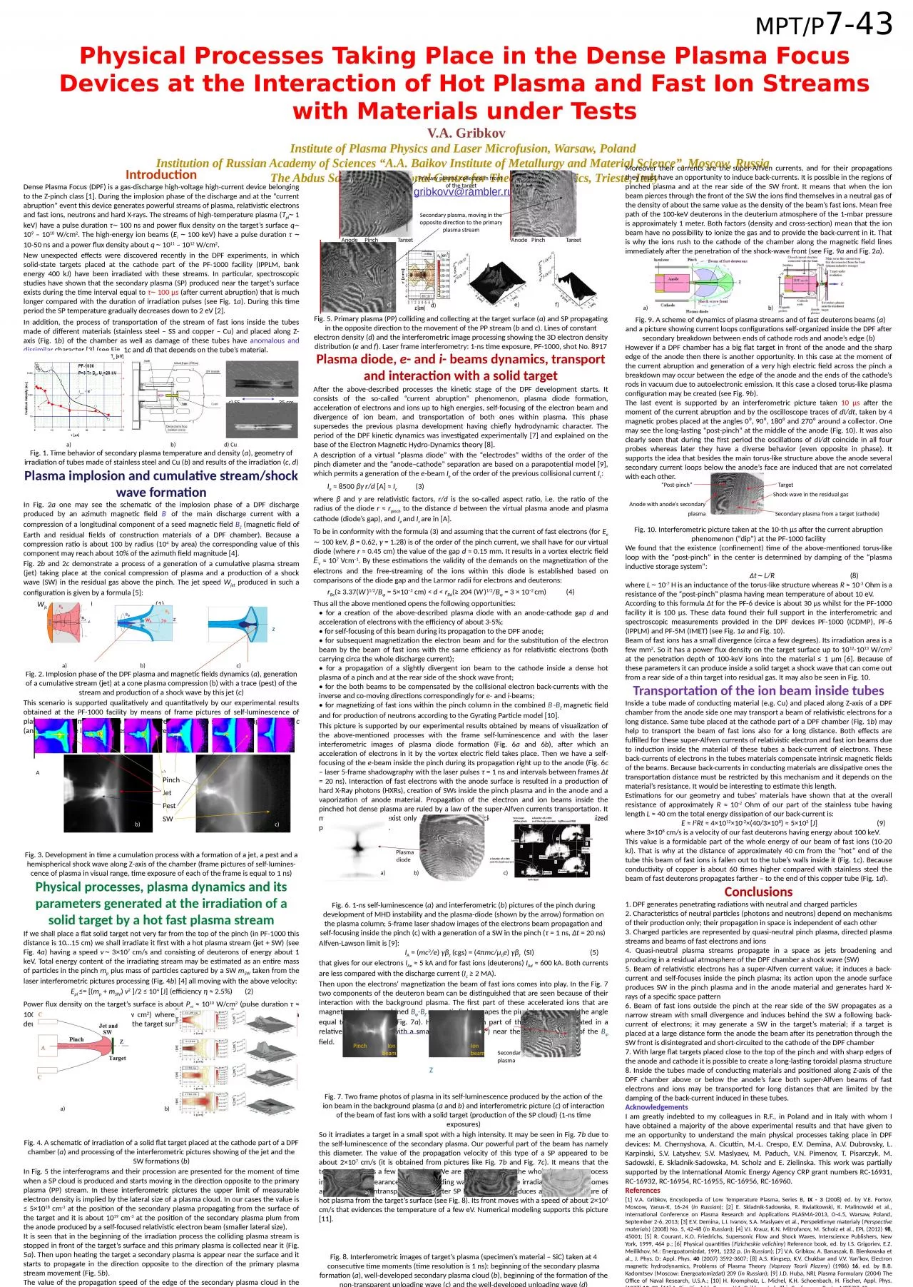
/
MPT/P 7-43 Physical  Processes Taking Place in the Dense Plasma Focus Devices at the Interaction MPT/P 7-43 Physical  Processes Taking Place in the Dense Plasma Focus Devices at the Interaction

MPT/P 7-43 Physical Processes Taking Place in the Dense Plasma Focus Devices at the Interaction - PowerPoint Presentation

TheCookieMonster
TheCookieMonster . @TheCookieMonster
Follow
342 views
Uploaded On 2022-08-04

MPT/P 7-43 Physical Processes Taking Place in the Dense Plasma Focus Devices at the Interaction - PPT Presentation

VA Gribkov Institute of Plasma Physics and Laser Microfusion Warsaw Poland Institution of Russian Academy of Sciences AA Baikov Institute of Metallurgy and Material Science Moscow ID: 935447

fig plasma pinch beam plasma fig beam pinch anode fast current ions electrons dpf target secondary stream time density

Share:

Link:

Embed:

Download Presentation from below link

Download Presentation The PPT/PDF document "MPT/P 7-43 Physical Processes Taking Pl..." is the property of its rightful owner. Permission is granted to download and print the materials on this web site for personal, non-commercial use only, and to display it on your personal computer provided you do not modify the materials and that you retain all copyright notices contained in the materials. By downloading content from our website, you accept the terms of this agreement.


Presentation Transcript

Slide1

MPT/P7-43Physical Processes Taking Place in the Dense Plasma Focus Devices at the Interaction of Hot Plasma and Fast Ion Streams with Materials under Tests V.A. GribkovInstitute of Plasma Physics and Laser Microfusion, Warsaw, Poland Institution of Russian Academy of Sciences “A.A. Baikov Institute of Metallurgy and Material Science”, Moscow, Russia The Abdus Salam International Centre for Theoretical Physics, Trieste, Italygribkovv@rambler.ru

IntroductionDense Plasma Focus (DPF) is a gas-discharge high-voltage high-current device belonging to the Z-pinch class [1]. During the implosion phase of the discharge and at the “current abruption” event this device generates powerful streams of plasma, relativistic electrons and fast ions, neutrons and hard X-rays. The streams of high-temperature plasma (Tpl ̴ 1 keV) have a pulse duration τ ̴ 100 ns and power flux density on the target’s surface q ̴ 109 – 1010 W/cm2. The high-energy ion beams (Ei ̴ 100 keV) have a pulse duration τ ̴ 10-50 ns and a power flux density about q ̴ 1011 – 1012 W/cm2.New unexpected effects were discovered recently in the DPF experiments, in which solid-state targets placed at the cathode part of the PF-1000 facility (IPPLM, bank energy 400 kJ) have been irradiated with these streams. In particular, spectroscopic studies have shown that the secondary plasma (SP) produced near the target’s surface exists during the time interval equal to τ ̴ 100 μs (after current abruption) that is much longer compared with the duration of irradiation pulses (see Fig. 1a). During this time period the SP temperature gradually decreases down to 2 eV [2].In addition, the process of transportation of the stream of fast ions inside the tubes made of different materials (stainless steel – SS and copper – Cu) and placed along Z-axis (Fig. 1b) of the chamber as well as damage of these tubes have anomalous and dissimilar character [3] (see Fig. 1c and d) that depends on the tube’s material. c) SS 35 cm a) b) d) CuFig. 1. Time behavior of secondary plasma temperature and density (a), geometry of irradiation of tubes made of stainless steel and Cu (b) and results of the irradiation (c, d)Plasma implosion and cumulative stream/shock wave formationIn Fig. 2a one may see the schematic of the implosion phase of a DPF discharge produced by an azimuth magnetic field B of the main discharge current with a compression of a longitudinal component of a seed magnetic field BZ (magnetic field of Earth and residual fields of construction materials of a DPF chamber). Because a compression ratio is about 100 by radius (104 by area) the corresponding value of this component may reach about 10% of the azimuth field magnitude [4].Fig. 2b and 2c demonstrate a process of a generation of a cumulative plasma stream (jet) taking place at the conical compression of plasma and a production of a shock wave (SW) in the residual gas above the pinch. The jet speed Wjet produced in such a configuration is given by a formula [5]: Wjet = W0/tg (α/2) (1) Z a) b) c)Fig. 2. Implosion phase of the DPF plasma and magnetic fields dynamics (a), generation of a cumulative stream (jet) at a cone plasma compression (b) with a trace (pest) of the stream and production of a shock wave by this jet (c)This scenario is supported qualitatively and quantitatively by our experimental results obtained at the PF-1000 facility by means of frame pictures of self-luminescence of plasma (having time resolution 1 ns) that are presented in subsequent Fig. 3a, b and c (anode A is at the left-hand sides of all pictures). A a) Fig. 3. Development in time a cumulation process with a formation of a jet, a pest and a hemispherical shock wave along Z-axis of the chamber (frame pictures of self-lumines-cence of plasma in visual range, time exposure of each of the frame is equal to 1 ns)Physical processes, plasma dynamics and its parameters generated at the irradiation of a solid target by a hot fast plasma streamIf we shall place a flat solid target not very far from the top of the pinch (in PF-1000 this distance is 10…15 cm) we shall irradiate it first with a hot plasma stream (jet + SW) (see Fig. 4a) having a speed v ̴ 3×107 cm/s and consisting of deuterons of energy about 1 keV. Total energy content of the irradiating stream may be estimated as an entire mass of particles in the pinch mp plus mass of particles captured by a SW mSW taken from the laser interferometric pictures processing (Fig. 4b) [4] all moving with the above velocity: Epl ≤= [(mp + mSW) v2 ]/2 ≤ 104 [J] (efficiency η ≈ 2.5%) (2)Power flux density on the target’s surface is about Ppl ≈ 1010 W/cm2 (pulse duration τ ≈ 100 ns, irradiated area S ̴ a few cm2) whereas a penetration depth of the plasma deuterons (of a 1-keV energy) into the target surface layer is about a few nm [6]. a) b)Fig. 4. A schematic of irradiation of a solid flat target placed at the cathode part of a DPF chamber (a) and processing of the interferometric pictures showing of the jet and the SW formations (b)In Fig. 5 the interferograms and their procession are presented for the moment of time when a SP cloud is produced and starts moving in the direction opposite to the primary plasma (PP) stream. In these interferometric pictures the upper limit of measurable electron density is implied by the lateral size of a plasma cloud. In our cases the value is ≤ 5×1018 cm-3 at the position of the secondary plasma propagating from the surface of the target and it is about 1019 cm-3 at the position of the secondary plasma plum from the anode produced by a self-focused relativistic electron beam (smaller lateral size).It is seen that in the beginning of the irradiation process the colliding plasma stream is stopped in front of the target’s surface and this primary plasma is collected near it (Fig. 5a). Then upon heating the target a secondary plasma is appear near the surface and it starts to propagate in the direction opposite to the direction of the primary plasma stream movement (Fig. 5b). The value of the propagation speed of the edge of the secondary plasma cloud in the direction to the anode is about 3×106 cm/s. It means that its temperature TSP is about 10 eV. Our numerical simulations support these figures.

Plasma diode, e- and i- beams dynamics, transport and interaction with a solid targetAfter the above-described processes the kinetic stage of the DPF development starts. It consists of the so-called “current abruption” phenomenon, plasma diode formation, acceleration of electrons and ions up to high energies, self-focusing of the electron beam and divergence of ion beam, and transportation of both ones within plasma. This phase supersedes the previous plasma development having chiefly hydrodynamic character. The period of the DPF kinetic dynamics was investigated experimentally [7] and explained on the base of the Electron Magnetic Hydro-Dynamics theory [8].A description of a virtual “plasma diode” with the “electrodes” widths of the order of the pinch diameter and the “anode–cathode” separation are based on a parapotential model [9], which permits a generation of the e-beam Ie of the order of the previous collisional current Ic: Ie ≈ 8500 βγ r/d [A] ≈ Ic (3)where β and γ are relativistic factors, r/d is the so-called aspect ratio, i.e. the ratio of the radius of the diode r ≈ rpinch to the distance d between the virtual plasma anode and plasma cathode (diode’s gap), and Ie and Ic are in [A]. To be in conformity with the formula (3) and assuming that the current of fast electrons (for Ee ∼ 100 keV, β = 0.62, γ = 1.28) is of the order of the pinch current, we shall have for our virtual diode (where r ≈ 0.45 cm) the value of the gap d ≈ 0.15 mm. It results in a vortex electric field Ev ≈ 107 Vcm−1. By these estimations the validity of the demands on the magnetization of the electrons and the free-streaming of the ions within this diode is established based on comparisons of the diode gap and the Larmor radii for electrons and deuterons: rBe(≥ 3.37(W)1/2/Bφ = 5×10⁻³ cm) < d < rBd(≥ 204 (W)1/2/Bφ = 3 × 10⁻² cm) (4)Thus all the above mentioned opens the following opportunities:• for a creation of the above-described plasma diode with an anode-cathode gap d and acceleration of electrons with the efficiency of about 3-5%; • for self-focusing of this beam during its propagation to the DPF anode;• for subsequent magnetization the electron beam and for the substitution of the electron beam by the beam of fast ions with the same efficiency as for relativistic electrons (both carrying circa the whole discharge current);• for a propagation of a slightly divergent ion beam to the cathode inside a dense hot plasma of a pinch and at the rear side of the shock wave front;• for the both beams to be compensated by the collisional electron back-currents with the inverse and co-moving directions correspondingly for e- and i-beams;• for magnetizing of fast ions within the pinch column in the combined B-BZ magnetic field and for production of neutrons according to the Gyrating Particle model [10]. This picture is supported by our experimental results obtained by means of visualization of the above-mentioned processes with the frame self-luminescence and with the laser interferometric images of plasma diode formation (Fig. 6a and 6b), after which an acceleration of electrons in it by the vortex electric field takes place. Then we have a self-focusing of the e-beam inside the pinch during its propagation right up to the anode (Fig. 6c – laser 5-frame shadowgraphy with the laser pulses τ = 1 ns and intervals between frames Δt = 20 ns). Interaction of fast electrons with the anode surface is resulted in a production of hard X-Ray photons (HXRs), creation of SWs inside the pinch plasma and in the anode and a vaporization of anode material. Propagation of the electron and ion beams inside the pinched hot dense plasma are ruled by a law of the super-Alfven currents transportation. It means that they can exist only with self-induced back-currents. It is possible in the ionized plasma of high density. Plasma diode Fig. 6. 1-ns self-luminescence (a) and interferometric (b) pictures of the pinch during development of MHD instability and the plasma-diode (shown by the arrow) formation on the plasma column; 5-frame laser shadow images of the electrons beam propagation and self-focusing inside the pinch (c) with a generation of a SW in the pinch (τ = 1 ns, Δt = 20 ns) Alfven-Lawson limit is [9]: IA = (mc3/e) γβz (cgs) = (4πmc/μ0e) γβz (SI) (5)that gives for our electrons IAe ≈ 5 kA and for fast ions (deuterons) IAd ≈ 600 kA. Both currents are less compared with the discharge current (Ic ≥ 2 MA).Then upon the electrons’ magnetization the beam of fast ions comes into play. In the Fig. 7 two components of the deuteron beam can be distinguished that are seen because of their interaction with the background plasma. The first part of these accelerated ions that are magnetized in the combined Bφ-BZ magnetic field escapes the pinch in the cone of the angle equal to about 25-30° (Fig. 7a). However the main part of the beam is propagated in a relatively narrow cone with a small divergence (≈ 5°) near the singularity line Z of the Bφ field. Secondary plasma ZFig. 7. Two frame photos of plasma in its self-luminescence produced by the action of the ion beam in the background plasma (a and b) and interferometric picture (c) of interaction of the beam of fast ions with a solid target (production of the SP cloud) (1-ns time exposures)So it irradiates a target in a small spot with a high intensity. It may be seen in Fig. 7b due to the self-luminescence of the secondary plasma. Our powerful part of the beam has namely this diameter. The value of the propagation velocity of this type of a SP appeared to be about 2×107 cm/s (it is obtained from pictures like Fig. 7b and Fig. 7c). It means that the temperature TSP is a few hundred eV. We are able to monitor the whole irradiation process including the appearance of the unloading wave in front of the irradiated area. It becomes apparent as a nontransparent cloud after SP blow-off that produces a relief of pressure of hot plasma from the target’s surface (see Fig. 8). Its front moves with a speed of about 2×106 cm/s that evidences the temperature of a few eV. Numerical modeling supports this picture [11].Fig. 8. Interferometric images of target’s plasma (specimen’s material – SiC) taken at 4 consecutive time moments (time resolution is 1 ns): beginning of the secondary plasma formation (а), well-developed secondary plasma cloud (b), beginning of the formation of the non-transparent unloading wave (c) and the well-developed unloading wave (d)Dependence of the physical processes dynamics on the target’s size and its distance from the anodeFast electrons and ions are charged particles. They interact with each other. They also represent currents and must be organized in closed circuits.

Anode Pinch Target Anode Pinch Target Fig. 5. Primary plasma (PP) colliding and collecting at the target surface (a) and SP propagating in the opposite direction to the movement of the PP stream (b and c). Lines of constant electron density (d) and the interferometric image processing showing the 3D electron density distribution (e and f). Laser frame interferometry: 1-ns time exposure, PF-1000, shot No. 8917

Moreover their currents are the super-Alfven currents, and for their propagations they must have an opportunity to induce back-currents. It is possible in the regions of pinched plasma and at the rear side of the SW front. It means that when the ion beam pierces through the front of the SW the ions find themselves in a neutral gas of the density of about the same value as the density of the beam’s fast ions. Mean free path of the 100-keV deuterons in the deuterium atmosphere of the 1-mbar pressure is approximately 1 meter. Both factors (density and cross-section) mean that the ion beam have no possibility to ionize the gas and to provide the back-current in it. That is why the ions rush to the cathode of the chamber along the magnetic field lines immediately after the penetration of the shock-wave front (see Fig. 9a and Fig. 2a). a) b) Fig. 9. A scheme of dynamics of plasma streams and of fast deuterons beams (a) and a picture showing current loops configurations self-organized inside the DPF after secondary breakdown between ends of cathode rods and anode’s edge (b)However if a DPF chamber has a big flat target in front of the anode and the sharp edge of the anode then there is another opportunity. In this case at the moment of the current abruption and generation of a very high electric field across the pinch a breakdown may occur between the edge of the anode and the ends of the cathode’s rods in vacuum due to autoelectronic emission. It this case a closed torus-like plasma configuration may be created (see Fig. 9b). The last event is supported by an interferometric picture taken 10 µs after the moment of the current abruption and by the oscilloscope traces of dI/dt, taken by 4 magnetic probes placed at the angles 0⁰, 90⁰, 180⁰ and 270⁰ around a collector. One may see the long-lasting “post-pinch” at the middle of the anode (Fig. 10). It was also clearly seen that during the first period the oscillations of dI/dt coincide in all four probes whereas later they have a diverse behavior (even opposite in phase). It supports the idea that besides the main torus-like structure above the anode several secondary current loops below the anode’s face are induced that are not correlated with each other. “Post-pinch” Target Shock wave in the residual gas Anode with anode’s secondary plasma Secondary plasma from a target (cathode) Fig. 10. Interferometric picture taken at the 10-th µs after the current abruption phenomenon (“dip”) at the PF-1000 facilityWe found that the existence (confinement) time of the above-mentioned torus-like loop with the “post-pinch” in the center is determined by damping of the “plasma inductive storage system”: Δt ̴ L/R (8)where L ̴ 10-7 H is an inductance of the torus-like structure whereas R ≈ 10-3 Ohm is a resistance of the “post-pinch” plasma having mean temperature of about 10 eV.According to this formula Δt for the PF-6 device is about 30 µs whilst for the PF-1000 facility it is 100 µs. These data found their full support in the interferometric and spectroscopic measurements provided in the DPF devices PF-1000 (ICDMP), PF-6 (IPPLM) and PF-5M (IMET) (see Fig. 1a and Fig. 10).Beam of fast ions has a small divergence (circa a few degrees). Its irradiation area is a few mm2. So it has a power flux density on the target surface up to 1012-1013 W/cm2 at the penetration depth of 100-keV ions into the material ≤ 1 μm [6]. Because of these parameters it can produce inside a solid target a shock wave that can come out from a rear side of a thin target into residual gas. It may also be seen in Fig. 10.Transportation of the ion beam inside tubesInside a tube made of conducting material (e.g. Cu) and placed along Z-axis of a DPF chamber from the anode side one may transport a beam of relativistic electrons for a long distance. Same tube placed at the cathode part of a DPF chamber (Fig. 1b) may help to transport the beam of fast ions also for a long distance. Both effects are fulfilled for these super-Alfven currents of relativistic electron and fast ion beams due to induction inside the material of these tubes a back-current of electrons. These back-currents of electrons in the tubes materials compensate intrinsic magnetic fields of the beams. Because back-currents in conducting materials are dissipative ones the transportation distance must be restricted by this mechanism and it depends on the material’s resistance. It would be interesting to estimate this length.Estimations for our geometry and tubes’ materials have shown that at the overall resistance of approximately R ≈ 10-2 Ohm of our part of the stainless tube having length L ≈ 40 cm the total energy dissipation of our back-current is: E ≈ I2Rt ≈ 4×1012×10-2×(40/3×108) ≈ 5×10³ [J] (9)where 3×108 cm/s is a velocity of our fast deuterons having energy about 100 keV.This value is a formidable part of the whole energy of our beam of fast ions (10-20 kJ). That is why at the distance of approximately 40 cm from the “hot” end of the tube this beam of fast ions is fallen out to the tube’s walls inside it (Fig. 1c). Because conductivity of copper is about 60 times higher compared with stainless steel the beam of fast deuterons propagates farther – to the end of this copper tube (Fig. 1d). Conclusions1. DPF generates penetrating radiations with neutral and charged particles2. Characteristics of neutral particles (photons and neutrons) depend on mechanisms of their production only; their propagation in space is independent of each other3. Charged particles are represented by quasi-neutral pinch plasma, directed plasma streams and beams of fast electrons and ions4. Quasi-neutral plasma streams propagate in a space as jets broadening and producing in a residual atmosphere of the DPF chamber a shock wave (SW)5. Beam of relativistic electrons has a super-Alfven current value; it induces a back-current and self-focuses inside the pinch plasma; its action upon the anode surface produces SW in the pinch plasma and in the anode material and generates hard X-rays of a specific space pattern6. Beam of fast ions outside the pinch at the rear side of the SW propagates as a narrow stream with small divergence and induces behind the SW a following back-current of electrons; it may generate a SW in the target’s material; if a target is placed at a large distance form the anode the beam after its penetration through the SW front is disintegrated and short-circuited to the cathode of the DPF chamber7. With large flat targets placed close to the top of the pinch and with sharp edges of the anode and cathode it is possible to create a long-lasting toroidal plasma structure 8. Inside the tubes made of conducting materials and positioned along Z-axis of the DPF chamber above or below the anode’s face both super-Alfven beams of fast electrons and ions may be transported for long distances that are limited by the damping of the back-current induced in these tubes.AcknowledgementsI am greatly indebted to my colleagues in R.F., in Poland and in Italy with whom I have obtained a majority of the above experimental results and that have given to me an opportunity to understand the main physical processes taking place in DPF devices: M. Chernyshova, A. Cicuttin, M.-L. Crespo, E.V. Demina, A.V. Dubrovsky, L. Karpinski, S.V. Latyshev, S.V. Maslyaev, M. Paduch, V.N. Pimenov, T. Pisarczyk, M. Sadowski, E. Skladnik-Sadowska, M. Scholz and E. Zielinska. This work was partially supported by the International Atomic Energy Agency CRP grant numbers RC-16931, RC-16932, RC-16954, RC-16955, RC-16956, RC-16960. References[1] V.A. Gribkov, Encyclopedia of Low Temperature Plasma, Series B, IX - 3 (2008) ed. by V.E. Fortov, Moscow, Yanus-K, 16-24 (in Russian); [2] E. Skladnik-Sadowska, R. Kwiatkowski, K. Malinowski et al., International Conference on Plasma Research and Applications PLASMA-2013, O-4.5, Warsaw, Poland, September 2-6, 2013; [3] E.V. Demina, L.I. Ivanov, S.A. Maslyaev et al., Perspektivnye materialy (Perspective materials) (2008) No. 5, 42-48 (in Russian); [4] V.I. Krauz, K.N. Mitrofanov, M. Scholz et al., EPL (2012) 98, 45001; [5] R. Courant, K.O. Friedrichs, Supersonic Flow and Shock Waves, Interscience Publishers, New York, 1999, 464 p.; [6] Physical quantities (Fizicheskie velichiny) Reference book, ed. by I.S. Grigoriev, E.Z. Meilikhov, М.: Energoatomizdat, 1991, 1232 p. (in Russian); [7] V.A. Gribkov, A. Banaszak, B. Bienkowska et al., J. Phys. D: Appl. Phys. 40 (2007) 3592-3607; [8] A.S. Kingsep, K.V. Chukbar and V.V. Yan’kov, Electron magnetic hydrodynamics, Problems of Plasma Theory (Voprosy Teorii Plazmy) (1986) 16, ed. by B.B. Kadomtsev (Moscow: Energoatomizdat) 209 (in Russian); [9] J.D. Huba, NRL Plasma Formulary (2004) The Office of Naval Research, U.S.A.; [10] H. Krompholz, L. Michel, K.H. Schoenbach, H. Fischer, Appl. Phys. (1977) 13, 29; [11] A. Cicuttin, M.L. Crespo, V.A. Gribkov et al., This Conference, Poster MPT/P7-40

Pinch

Jet

Pest

SW

b

)

c

)

a)

b

)

c

)

d

)

e

)

f)

a)

b

)

c

)

Primary plasma, collected in front of the target

Secondary plasma, moving in the opposite direction to the primary plasma stream

Pinch Ion

beam

Ion beam

a)

b

)

c

)

d

)