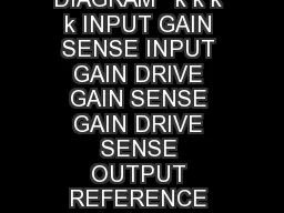
/
FUNCTIONAL BLOCK DIAGRAM   k k k k INPUT GAIN SENSE INPUT GAIN DRIVE GAIN SENSE GAIN DRIVE FUNCTIONAL BLOCK DIAGRAM   k k k k INPUT GAIN SENSE INPUT GAIN DRIVE GAIN SENSE GAIN DRIVE

FUNCTIONAL BLOCK DIAGRAM k k k k INPUT GAIN SENSE INPUT GAIN DRIVE GAIN SENSE GAIN DRIVE - PDF document

alexa-scheidler
alexa-scheidler . @alexa-scheidler
Follow
615 views
Uploaded On 2014-12-18

FUNCTIONAL BLOCK DIAGRAM k k k k INPUT GAIN SENSE INPUT GAIN DRIVE GAIN SENSE GAIN DRIVE - PPT Presentation

D Information furnished by Analog Devices is believed to be accurate and reliable However no responsibility is assumed by Analog Devices for its use nor for any infringements of patents or other rights of third parties which may result from its use ID: 25993

Information furnished

Share:

Link:

Embed:

Download Presentation from below link

Download Pdf The PPT/PDF document "FUNCTIONAL BLOCK DIAGRAM k k k k INPUT..." is the property of its rightful owner. Permission is granted to download and print the materials on this web site for personal, non-commercial use only, and to display it on your personal computer provided you do not modify the materials and that you retain all copyright notices contained in the materials. By downloading content from our website, you accept the terms of this agreement.


Presentation Transcript

FUNCTIONAL BLOCK DIAGRAM +Ð Ð Ð Ð Ð 5010k10k10k10kVBSENSEDRIVE+GAINSENSE+GAINDRIVESENSE                         AD625A/J/S AD625B/K AD625C ModelMinTypMaxMinTypMaxMinTypMaxUnit 2RFRG 1 2RFRG 1 2RFRG Gain Range110,000110,0001110,0000.001% �Gain2560.005% 555ppm/Gain Sense Current300vs. Temperature520215210nA/Gain Sense Offset Current150 vs. Temperature215110210nA/Input Offset Voltage50vs. Temperature12/Output Offset Voltage4vs. Temperature2050/1025/90dBG = 1085959010095105dBG = 10095100105110110120dB 140dB50pA/ 20pA/Differential Resistance111GDifferential Capacitance444pFCommon-Mode Resistance111GCommon-Mode Capacitance444pF10V 12VÐG2 VD 12VÐG2 VD 12VÐG2 90dBG = 10909590105100115dBG = 100100105105115110125dB 140dB @ 5 mA@ 5 mA@ 5 mA)650650650kHzG = 10400400400kHzG = 100150150150kHzG = 1000252525kHzSlew Rate5.05.05.0V/G = 1 to 200151515G = 500353535 G = 1000757575AD625ÐSPECIFICATIONS  AD625 AD625A/J/S AD625B/K AD625C ModelMinTypMaxMinTypMaxMinTypMaxUnitR.T.I.444nV/R.T.O.757575nV/G = 1101010G = 101.01.01.0G = 1000.30.30.3G = 10000.20.20.2 0.1 Hz to 10 Hz606060pA p-p101010k30303010V Gain to Output1 0.011 0.011 0.01%202020k30303010V Gain to Output1 0.011 0.011 0.01%J/K Grades0+700+7040+8540+8540+8555+125 65+15065+15065+15018V Quiescent Current3.553.553.55mA is the maximum differential input voltage at G = 1 for specified nonlinearity. V at other gains = 10 V/G. V = actual differential input voltage. = 0.50; V = 12 V (10/2 0.50 V) = 9.5 V. are tested on all production units at final electrical test. Results from those tests are  AD625PIN CONNECTIONSCeramic DIP (D) and Plastic DIP (N) Packages RTI NULLRTO NULLRTI NULLRTO NULLNCSENSEREFERENCEV 10kÐVS123467161511109Leadless Chip Carrier (E) Package 2019910111213SupplyVoltage . . . . . . . . . . . . . . . . . . . . . . . . . . . . . . . . .18VInternalPowerDissipation . . . . . . . . . . . . . . . . . . . . . .450 mWInput Voltage . . . . . . . . . . . . . . . . . . . . . . . . . . . . . . . . . . .DifferentialInputVoltage . . . . . . . . . . . . . . . . . . . . . . . . .Output Short Circuit Duration . . . . . . . . . . . . . . . .IndefiniteStorage Temperature Range (D, E) . . . . . . . .Storage Temperature Range (N) . . . . . . . . . . ESD (electrostatic discharge) sensitive device. Electrostatic charges as high as 4000V readilyAlthough the AD625 features proprietary ESD protection circuitry, permanent damage mayoccur on devices subjected to high-energy electrostatic discharges. Therefore, proper ESD precautions are recommended to avoid performance degradation or loss of functionality. WARNING!ESD SENSITIVE DEVICE ORDERING GUIDE ModelTemperature RangePackage DescriptionPackage OptionC16-Lead Ceramic DIPD-16C16-Lead Ceramic DIPD-16C16-Lead Ceramic DIPD-16C16-Lead Ceramic DIPD-16C16-Lead Ceramic DIPD-16AD625SD/883BC16-Lead Ceramic DIPD-16C20-Terminal Leadless Chip CarrierAD625JN0C16-Lead Plastic DIPN-16AD625KN0C16-Lead Plastic DIPN-16CDieCDieC20-Terminal Leadless Chip Carrier C16-Lead Ceramic DIPD-16AD625J/K . . . . . . . . . . . . . . . . . . . . . . . . . . . .0AD625A/B/C . . . . . . . . . . . . . . . . . . . . . . . .AD625S . . . . . . . . . . . . . . . . . . . . . . . . . . .Lead Temperature Range (Soldering10sec) . . . . . . . .+300*Stresses above those listed under Absolute Maximum Ratings may cause perma-nent damage to the device. This is a stress rating only; functional operation of thesection of this specification is not implied. Exposure to absolute maximum rating SUPPLY VOLTAGE Ð VINPUT VOLTAGE RANGE Ð V200 5101520 % &     101001k10k100k10M % $*+% , 1.02.03.04.05.06.07.08.0 % 12   --  5101520 % "2    ' 10k100k1M G = 500G = 100BANDWIDTH % 34 ' % , 1001k10k100k VS = Ð15V dc+1V p-p SINEWAVE % 5  6' 1001k10k % #2    ' 1k10k100k1M10M % 7( % , 1001k10k100k = +15V dc+ % 86  6' Typical Performance Characteristics AD625 CINPUT CURRENT Ð nA40Ð 252575125 % &9 : *   5101520 % &#; *   % &74 % ,   % &&2  (  1 101001k10k100k G = 1G = 10 % &$- '  VS VS F1F1FG = 1, 10, 1001k % &1 - *  % &"( 2    100k 101001k10k100k % &3 *    % &54 % ,   AD625 % &84 ' 6 % ""4 ' 6 10203040506070 G = 1G = 100G = 1000G = 1000G = 100G = 1 % "9�' -  99& VS % "#' - - *  % "&4 ' 6 % "$4 ' 6 construction and laser-wafer-trimming allow the tight matchingQ4) provides additional gain to A1 andA2. Feedback from the outputs of A1 and A2 forces the collec-Q4 to be constant, thereby, impressing theoutputs of A1 and A2 which is given by the gain (2R + 1)gain subtracter, A3, removes any common-mode signal from the is the determining factor of the transconduc-tance of the input preamp stage. As R is reduced for largervery high open-loop gain of (3 10 at programmed g 500) + 100) inseries with two diode drops (approximately 1.2 V) between theplus and minus inputs, in either direction. With no external protec- very small (i.e., 40 pproximately2.5 V. Figure 26a shows the external components necessary to VB+Ð A50A1A2Q1, Q3Q2, Q4A50 S % "3' *    7"326b, provides adequate protection. Figure 26c shows low costFETs with a maximum ON resistance of 300 configured to offerDuring differential overload conditions, excess current will flowused in an SPGA application with a CMOS multiplexer, thisbilities of the multiplexer may be the limiting factor in allowableoverflow current. The ON resistance of the switch should beincluded as part of R when calculating the necessary input AD625ÐVS FRGRF FD333 +IN1.4k % "7  6   *  ÐVS FRGRF FD333 +IN500 1N5837A % "7 6   *   (?3 ÐVS FRGRF +IN % "7 6   *  resistors in Figure 26a will degrade the 4kTRext/Hz)2 7.9 nal resistors are needed to select any gain from 1 to 10,000.AD625C contributes less than 0.02% to gain error and underC gain TC. The gain sense current is insensitive toAs previously stated each R provides feedback to the input for RRTO errors increases with increasing feedback resistance, values are not recommended (values below 10 k may lead to instability). Refer to the graph of RTO noise, = 2 R l). +GAINÐRTI NULLRTI NULLRTONULLRTONULL+GAIN DRIVEÐFRGRFREFVSVRG % "17"3%@( *   sary; in these cases the RTI null should be used. RTO OFFSET VOLTAGE DRIFT6542160k50k40k30k20k10kMULTIPLYING FACTOR 1101001k RTO NOISERTO OFFSET VOLTAGE10k20k30k40k50k60k10k20k30k40k50k60k FEEDBACK RESISTANCE Ð FEEDBACK RESISTANCE Ð  % "5-2 2    :  Table I.Common Gains Nominally Within GAINR120 k219.6 k520 k1020 k2020 k5019.6 k10020 k20020.5 k50019.6 k100019.6 k420 k819.6 k1620 k3219.6 k6420 k12820 k25619.6 k51219.6 k 102419.6 kstances the sense terminal can be wired to the load thus putting R drops and virtually eliminating thisTypically, IC instrumentation amplifiers are rated for a full shows how a high-current booster may be connected of an instrumentation amplifier. By using an external AD625ÐV S FRGRF VV RI % "87"3B       2  The reference terminal may be used to offset the output by up10 V. This is useful when the load is or does notCMR trim by the ratio of 10 k = 80 dB). An operational amplifier may be used toprovide the low impedance reference point as shown in FigureThe circuit of Figure 30 also shows a CMOS DAC operating in R5/R4), however, to be symmetri-cal about 0 V R3 = 2 R4.where N = number of bits of the DAC. The range of offset for120 mV, and the offset is incremented in steps of AD625ÐVS GNDV AD712 AD712 AD5891.2V% #9'   *   2 An instrumentation amplifier can be turned into a voltage-to- AD625 FRGRF V L % #&  0 0*  *   side of a current settingresistor, an output current may be defined as a function of input will largely flow through the load. Offset anddrift specifications of A2 must be added to the output offset andmerit for instrumentation amplifiers. While initial offset may bevariations will cause errors. Intelligent systems can often correct dominate at high gains and output errors dominate at low gains.an RTI error.By separating these errors, one can evaluate the total error inde-(RTO) by the following formula:Total Error RTI = input error + (output error/gain) input error) + output errorC, RTO.in distributed stray capacitances. In many applications shieldedcables are used to minimize noise. This technique can create AD625ÐVS FRGRF 100 % #"* 0+ '  common-mode rejection errors unless the shield is properlydriven. Figures 32 and 33 show active data guards which are the capacitances of the input cabling, thus minimiz- AD625ÐVS FRGRF +INPUTVS % ##   '  In order to isolate low level analog signals from a noisy digitalground line, however, current through ground wires and pc runsTherefore, separate ground returns should be provided to mini-mize the current flow from the sensitive points to the systemnal, it can solve many grounding problems. AD625 VS VS SAMPLEANDHOLD CAP VS SIGNAL ANALOGOUT VS % #$: ( 6     ,  '  input sources such asfrom each input to ground as shown in Figure 35. AD625ÐVS FRGRF % #3 (    : *   -   *   ÐVS FRGRF % #3(    : *   -   ÐVS FRGRF % #3(    : *   **  At room temperature, offset effects can be nulled by the use of or thermocouple emf can be measured. Standard IClead material (kovar) and copper form a thermocouple with aincludes the input leads (1, 16) and the gain sense lines (2, 15). AD625ÐVS GNDV 1516 GNDAD7510DIKD A1A2A3A4 200s V 11 noise. In SPGAapplications relay contacts and CMOS mux leads are bothof band signals (i.e., RF interference). When amplifying small bases andthese unwanted signals. In Figure 37, the RC time constantshould be chosen for desired attenuation of the interfering signals. +GAIN SENSE+INRTI NULLRTI NULLRTONULLRTONULLFRGRFREFVSV 215CAP % #1*     %    AD625 % #8'6( + @  '  Figure 39 shows a complete SPGA feeding a 12-bit DAS with a10 V input range. This configuration was used in the errorbudget analysis shown in Table II. The gain used for the RTIcalculations is set at 16. As the gain is changed, the ON resis-tance of the multiplexer and the feedback resistance will change,which will slightly alter the values in the table.Table II.Errors Induced by Multiplexer to an SPGA Induced Specifications Voltage Offset ErrorAD625CAD7520KNCalculationInduced RTIRTI OffsetGain SenseSwitch40 nA =6.8 VoltageOffsetResistance6.8 Current170 RTI OffsetGain SenseDifferential60 nA 6.8 =0.41 VoltageCurrentSwitch0.41 60 nAResistance RTO OffsetFeedbackDifferential2 )0.5 VoltageResistanceLeakage= 8 Current (I RTO OffsetFeedbackDifferential2 (1 nA 20 k)2.5 VoltageResistanceLeakage= 40 Ð1 nATotal error induced by a typical CMOS multiplexer C10.21 is recommended value (see Resistor Programmable Gain Amplifier section). and I of the*The frequency response and settling will be affected by the ON resistance andmatch the extraneous capacitance at Pins 15 and 2, and Pins 1An SPGA provides the ability to externally program precisiongains from digital inputs. Historically, the problem in systemsand gain drifts. The AD625 eliminates this problem by makingremoved from the signal current path. This transforms the ONresistance error into a small nullable offset error. To clarify this +GAINRTI NULLRTI NULL+VNCREFVSV 215 TTL/DTL TO CMOS LEVEL TRANSLATOR DECODER/DRIVER A1NVGND VSRTO NULLRTO NULL equals the resistance between the gain sense equalsthe sum of the two 975 resistors and the 650 resistor, or equals the resistance between the gain sense and the resistor plus the 3.9 k resistor, or 19.5 k 2RFRG 2(19.5(2.6 As the switches of the differential multiplexer proceed synchro- and R change, resulting in the various programmed AD625 4166425610244096 = 0 % $9�-  99&  "9'   '6( 7"3formula must be a series where the present term is dependent on RkR201. A dummy variable (j) serves as a counter to keep arunning total of the preceding feedback resistors. To illustrate feedback resistors as shown in Figure 41.2) Before making any calculations it is advised to draw a resistor M) + 1 resistors, where M = number of gains. resistors3) Begin all calculations with = 1 and = 0. = (20 = 0 = 15 = [20 + = [20 + + + = 18.75 = 937.5 of the highest gain setting), is deter-mined last. Its value is the remaining resistance of the 40 k RkR402 + R + R Ð 3 = 625 5)If different resistor values are desired, all the resistors in thethe total network resistance below 20 k can result in ampli-fier instability. More information on this phenomenon isnetwork in Figure 38 has a scaling factor of 650/625 = 1.04,if this factor is used on R6)Round off errors can be cumulative, therefore, it is advised to % $&   ( '    / Dimensions shown in inches and (mm). 16 PIN 1 0.755 (19.18)0.745 (18.93) 0.26 (6.61)0.24 (6.1) SEATING 0.17 (4.32)MAX0.02 (0.508)0.015 (0.381) 0.12 (3.05) 0.065 (1.66) 0.14 (3.56)0.12 (3.05) 0.012 (0.305)0.008 (0.203) 20-Terminal Leadless Chip Carrier (E-20A) 1981914 45 45 0.050(1.27) 45 45 16-Lead Ceramic DIP (D-16) 1689 0.2650.010 0.3100.01 0.125 (3.175)MIN0.047 0.100 (254)+0.0030.43+0.076 0.700 (17.78) BSC 0.010 6 - C'