/
Whisper 100 Owners Manual Whisper 100 Owners Manual

Whisper 100 Owners Manual - PDF document

alexa-scheidler
alexa-scheidler . @alexa-scheidler
Follow
410 views
Uploaded On 2016-08-24

Whisper 100 Owners Manual - PPT Presentation

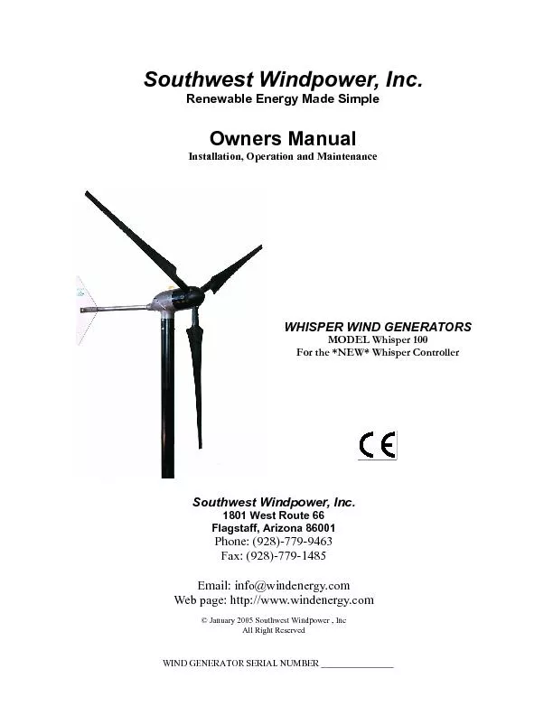
Document 0211 REV C SOUTHWEST WINDPOWER 12312005 Installation Operation and Maintenance Southwest Windpower Inc Email infowindenergycom Web page httpwwwwindenergycom ID: 455735

Document #0211 REV SOUTHWEST

Share:

Link:

Embed:

Download Presentation from below link

Download Pdf The PPT/PDF document "Whisper 100 Owners Manual" is the property of its rightful owner. Permission is granted to download and print the materials on this web site for personal, non-commercial use only, and to display it on your personal computer provided you do not modify the materials and that you retain all copyright notices contained in the materials. By downloading content from our website, you accept the terms of this agreement.


Presentation Transcript

Whisper 100 Owners Manual Document #0211 REV C SOUTHWEST WINDPOWER 12/31/2005 Installation, Operation and Maintenance Southwest Windpower, Inc. Email: info@windenergy.com Web page: http://www.windenergy.com © January 2005 Southwest Windpower , Inc All Right Reserved WIND GENERATOR SERIAL NUMBER ________________ WHISPER WIND GENERATORS Southwest Windpower, Inc. Renewable Energy Made Simple SOUTHWEST WINDPOWER Whisper 100 Owners Manual Document #0211 REV C 12/31/2005 Introduction Introduction 1. Tower Installation 2. Battery Selection 3. Battery Configuration and Location 4. Setting Wind Turbine Voltage 5. Wind Turbine Electrical Tests 11 6. Mounting Wind Turbine On Tower 7. Whisper Controller - Mounting 8. Whisper Controller - Wiring 14 9. Whisper Controller - PCB Switches and Reset Button 16 11. Tail Installation 12. Blade and Nose Cone Installation 13. Operation of Whisper Controller 14. Maintenance - Monthly 15. Maintenance - Annual 16. Troubleshooting and Repair 17. Mechanical Repair and Replacement 10. Optional Display Installation Table of Contents FOLLOW STEP-BY-STEP INSTALLATION LOOK FOR THE SHADED BOXES AND FOLLOW THE STEPS IN ORDER. CHECK THE PROVIDED BOX WHEN COMPLETE. SUGGESTED TOOLS AND EQUIPMENT YOU WILL NEED Round or Half Round File Pliers 10mm or 3/8” Metal Cutting Drill Bit Metric wrenches and sockets Torque Wrench (20 Nm / 15 ft-lb) Large Adjustable Wrench Blue Loctite 242 Electrical tape Sawhorse Hex Wrenches Set (metric) Electrical Wire (see p. 6) Ground Rod and Clamp Electric Drill Motor Soldering Iron and Solder 2 Table of Contents SOUTHWEST WINDPOWER Whisper 100 Owners Manual Document #0211 REV C 12/31/2005 DESCRIPTION OF SYSTEMS The illustration below depicts a typical installation. For more information regarding specifications of wind, wind/solar and inverter systems, contact Southwest Windpower. Note that the illustration below is for information purposes only. See the appropriate section to properly wire your own wind system. Whisper Wind Generators include the Whisper Controller System Center and the user supplies the battery, tower, inverter and wiring. During windless periods, solar panels may supplement your usage of renewable energy. Solar PV (photovoltaic) panels make electricity directly from sunlight. Batteries store electricity so you have power during windless and sunless periods as well as periods of high demand. A deep cycle type of battery must be used. If you have the wind generator only, use this manual to help size the battery and inverter. Introduction Whisper 100 Owners Manual Document #0211 REV C SOUTHWEST WINDPOWER 12/31/2005 Installation Wind Generator Model Whisper 100 Battery System Volts 12, 24, 36, 48 Minimum Amp x Hours (20 hour rate) 200 Minimum Kilowatt Hours (Volts x Amps x Hours/1000) 4 Tower height minimum: 7m (20 ft) above trees or obsta-cles within 100m (300 ft). 100m (300 ft) (Install tower following manufacturer’s instructions.)Tower height minimum is 7 meters (20 feet) above trees or obstacles within 100m (300ft). The highest point on your property is generally best, but wind generator dis-tance to battery and the battery voltage determine the correct wire size (Refer to wire size table pg. 6). A self supporting tower occupies less ground area than a guyed tower but is more expensive. A tilt-up design permits easy installation and maintenance on the ground and eliminates the need for climbing. The Whisper 100 is suitable for side-of-building mount-ing on unoccupied buildings such as garage or barn. Some vibration transmission will be noticeable from mounts to structure. Foundations must be designed and approved for local wind/soil conditions. Consult with a professional engineer to determine proper type and location of tower installation. Side of Building Mount Mounting MINIMUM BATTERY SIZES 1. Tower Installation 2. Battery Selection See Table belowfor minimum battery size. 7 SOUTHWEST WINDPOWER Whisper 100 Owners Manual Document #0211 REV C 12/31/2005 Locate battery in moderately stable room temperature, dry unoccupied building. Battery performance is optimal at room temperatures. Run AC power from inverter to house or load. If battery is in an occupied building, an enclosure with vent to outside is required. Follow code. See the following diagrams for package system series/parallel arrangement. Determine series/parallel arrangement and construct a rack or mount from heavy, treated lumber, or other suitable material. Allow 5 cm (2 in) on all sides for ventilation. Allow 60 cm (2 ft) vertical clearance for access to terminals and checking water. Coat all connections with grease or corrosion protector available at auto parts store. Install Whisper Controller and Inverter fuse (if used) at battery positive. To minimize the possibility of EMI (electromagnetic interference), the line from the battery to the should be less (3 meters). 12 Volt Configuration Inverter Inverter Whisper Controller Whisper Controller 24 Volt Configuration Inverter Inverter Whisper Controller Whisper Controller Inverter Whisper Controller 48 Volt Configuration Inverter Whisper Controller Nut and Bolt Battery Positive Drill one end of fuse to fitbattery post, if necessary. JJN-100 IR 200kA Use the diagrams below to determine the series/parallel arrangement for your system voltage (typical 6 volt battery arrangement Recommended Battery Fuse Installation (Consult local electrical codes) Fuse Included 3. Battery Configuration and Location Installation SOUTHWEST WINDPOWER Whisper 100 Owners Manual Document #0211 REV C 12/31/2005 Voltage Configuration Wiring Table Reference the following table to determine the correct brush and stator wire connections for your voltage configu-ration. Note the correct color (size) wire nut is indicated for each connection. Red Wire Nuts BRUSH WIRE BRUSH WIRE BRUSH WIRE WHITE 1 WHITE - RED 1 WHITE 3 WHITE 2 RED 3 BLACK 2 RED 2 BLACK 1 BLACK - RED - BLACK 3 Red Wire Nuts Yellow Wire Nuts BRUSH WIRE BRUSH WIRE BRUSH WIRE WHITE - WHITE 2 WHITE 1 RED 2 BLACK 1 RED 3 RED 1 WHITE 3 RED - BLACK 3 BLACK - BLACK 2 Red Wire Nuts Yellow Wire Nuts BRUSH WIRE BRUSH WIRE BRUSH WIRE WHITE - WHITE 2 RED 2 BLACK 2 WHITE 1 RED - BLACK 1 RED 1 WHITE 3 RED 3 BLACK 3 BLACK - Whisper 100 Owners Manual Document #0211 REV C SOUTHWEST WINDPOWER 12/31/2005 Refer to the figures below and wire the resistive “dump” load for your system voltage. Sufficient jumper wires are provided with the Whisper Controller such that any 12, 24, 36 and 48 volt configuration can be accomplished. 24 and 36 Volt Systems 12 Volt Systems 48 Volt Systems Once startup is successful and the red LED can be cycled by toggling the Diversion Switch, then set the switch to “Stop” (Red LED on) and connect the turbine wires to the controller (order of the turbine wires is not important). With the Red LED is on, the turbine will not spin as long as at least two of its wires are connected. For further opera-tional information refer to Whisper Controller Operation on page 22. Optional Anemometer Connection The Whisper Controller has been designed to accommodate a Model #40 anemometer, manufactured by NRG. Other equivalent anemometers may work, compare manufacturers specifications. A terminal block on the circuit board is the connection point for the two anemometer signal wires.The terminal block connections are labeled +/-, the polarity should be observed since some anemometers require specific polarity connec-tions. A ground shield (if applicable) should be connected to the controller’s grounding terminal. To achieve the most meaningful air speed data the anemometer should be mounted on the turbine tower as near as pos-sible to the turbine without entering the turbine’s sphere of operation. See the manufacturer’s recommended installation instructions. SOUTHWEST WINDPOWER Whisper 100 Owners Manual Document #0211 REV C 12/31/2005 Installation Whisper Controller Components The optional display was designed to be mounted either on the Whisper Controller base unit, or in a wall type switch re-ceptacle. Hardware is provided with the display. There is a short ethernet CAT5 cable provided for Controller base instal-lation. Local Display Installation If the display is to be mounted directly on the Whisper Controller you will need to remove the electronics cover and knock out the sheet metal insert where the display will mount. There are pre-drilled holes to mount the display. Use the provided 8-32 x 3/8”, black oxide, stainless steel screws, and 8-32 nuts with captive star washers to mount the display to the elec-tronics cover. Connect the display cable to the CAT5 jack located nearest the diversion switch. This will indicate to the display that it is locally mounted and it will disable its LED features, since these are redundant to those mounted on the Whisper Controller base. Leave the cover off until the display function is verified. Remote Display Installation The display may be located in a remote location (up to 300 meters / 1000 feet) away from the Whisper Controller. Use Category 5 ethernet cable will have to be purchased. Install the display in the desired location and connect the ethernet cable to the display unit. Remove the electronics cover on the Whisper Controller. If necessary, knock out one of the sheet metal plugs in the Whis-per Controller base unit and route the ethernet cable inside the unit. Plug the ethernet cable into the jack in the lower rightcorner of the controller board. Leave the cover off until the display function is verified. Display Function Verification Once the display is plugged into the controller base and the batteries are connected to the controller there should be text displayed on the LCD display. If the display is blank there is a contrast adjusting potentiometer that can be adjusted to brighten the display. Insert a bladed screwdriver into the hole on the display between the buttons and the LEDs. Turn the potentiometer to adjust the brightness. If a display is still not visible disconnect and reconnect the cable to the display to reset the display. Once display function is verified re-install the electronics cover on the controller base. The system wiring is now complete. Proceed to assembling the turbine and mounting blades to rotor. 18 Whisper Controller Display Whisper Controller Resistive Load bank (Dumpload) Whisper Controller Electronic Cover Whisper Controller Electronics Diversion Switch and LED’s (Far Side) Whisper Controller Regulation Potentiometer 10. Optional Display Installation Whisper 100 Owners Manual Document #0211 REV C SOUTHWEST WINDPOWER 10/05/05 Item Description Quantity Nose Cone 1 Flat Washer, M8 x 24 9 Hex Bolt, M8 x 50 9 Lock Washer, M8 6 Hex Bolt, M8 x 55 3 Nylock Nut, M8 6 Blade Strap 3 WHISPER 100 Blade Installation 1. Flat (ribbed) side of blade lays against rotor front plate. 2. Use thread locking compound (Loctite 242 or equivalent) on all bolts. 3. Loosely install all items except Item 2 (Nose Cone). Insure that Item 8 (blade strap) is contacting the top portion of the blade as shown below. Note # 6 bolts are slightly longer than # 4 bolts and must go in a specific location. 4. Start by installing outboard hardware 4 (Bolt, M8 x 50) , 3 (Flat Washer, M8 x 24), and 7 (Nylock Nut, M8). Install Items 4 (Bolt, M8 x 50) and 5 (Lock Washer, M8) on innermost rotor bolt circle. This inner bolt circle will be cov-ered by Item 2 (Nose Cone) in step 6. 5. Torque all Item 4 (Bolt, M8 x 50) to 8 ft/lbs (11Nm). Do not over-tighten. 6. Install Item 2 (Nose Cone) using Item 3 (Flat Washer, M8 x 24), 5 (Lock Washer, M8), and 6 (Bolt, M8 x 55). 7. Torque remaining bolts to 8 ft/lbs (11Nm). 12. Blade and Nose Cone Installation Installation 3 1 8 5 4 2 6 5 3 4 SOUTHWEST WINDPOWER Whisper 100 Owners Manual Document #0211 REV C 10/05/05 Normal Operation—Whisper Controller 23 Normal Operation – Whisper Controller DisplayThe Whisper Controller Display adds a tremendous set of features to your Whisper wind turbine system. Controller measurements can be monitored and operational parameters can be adjusted. Take the time to learn about your Whisper Controller Display to take advantage of its many features. 6. Whisper Controller Display LED Display Functionally, the Display unit’s LEDs operate the same as the Controller’s LEDs (see Section 13 - Operation of Whis-per Controller). Due to communication lag times, there may be subtle difference in these two sets of LEDs. There-fore, it is recommended that if the Display is mounted in the lid of the Controller, that the Display be plugged into the Controller board jack in the lower right corner of the Controller board. This will automatically disable the Display’s LEDs. The Controller board jack closest to the Diversion switch should be used for a remotely mounted display. LCD Display Screen Green LED Red LED LCD Contrast Adjustment “A” Menu Function Button “B” Menu Function Button LCD Contrast Potentiometer The contrast potentiometer can be accessed through the cover of the Display unit via a hole situated between the but-tons and the LEDs. The pot is optimized at the factory for room temperature operation; however, deviations from room temperature can cause the LCD to appear too dark or too light. Carefully insert a screwdriver through the dis-play lid and turn the potentiometer counter-clockwise to increase the darkness of the LCD. Display Operation Overview The basic navigational structure of the display pages are rings with the structure shown in the figure on page 20. Each of the menu pages in this main ring structure is an access point for various controller and display settings. The “A” Function buttons scroll between the menu pages, or change parameters on the menu, or sub-pages. The Ref-erence Numbers in the following paragraph headings refer to menu pages shown in the table on page 19. When first connected, the Display begins with the Main Page. The Main Page displays all of the Controller’s meas-ured parameters, including battery charging status, windspeed, charging voltage, battery charge current, and turbine power. There are four sub-pages associated with this page. From the Main Display the “A” Function button moves through the Energy and History menu pages. From the Main Display the “B” Function button moves through the Mode and Regulation menu pages. Energy Page (2) Displayed on the Energy page is the accumulated kilowatt-hours and kilo amp-hours since the last reset. These can be reset from the reset sub-menu. The leftmost numbers are reset at the factory. From the Energy page the “A” menu button will go to the History page. The “B” menu button will go to the Energy Reset page. History Page (3) Displayed on this page are the average and peak windspeed and turbine power since the last reset. Windspeed is only available if the optional anemometer is installed. Both of these readings can be reset via the reset menu. From the History page the “A” menu button will go to the Main Display page. The “B” menu button will go to the History Reset page. SOUTHWEST WINDPOWER Whisper 100 Owners Manual Document #0211 REV C 10/05/05 Normal Operation—Whisper Controller Energy Histor Main Regulation RegulationRegulation “A” Reset “B” Charge “A” “B” “B” “B” IncreaseSet PointIncrease Display Menu Ring Structure Whisper 100 Owners Manual Document #0211 REV C SOUTHWEST WINDPOWER 10/05/05 ts! Record ALL maintenance and repair work! Date Maintenance Whisper 100 Owners Manual Document #0211 REV C SOUTHWEST WINDPOWER 10/05/05 Table: Symptoms of Mechanical Problems a. Ice in generator, or ice on propeller b. Debris between rotor and stator c. Loose, broken or rubbing magnet d. Bad or worn bearing i. Wait for warm weather i. Turn propeller gently by hand and blow or use piece of paper to dislodge debris i. Contact factory or distributor to remove rotor and re-glue magnets i. Contact factory or distributor to replace bearing(s) a. Same as above, except more likely to be high magnet or bad bearing. b. Swelled wire keepers due to high moisture i. Same as above a. Ice on blade b. Dirty blade c. Split, warped or damaged blade d. One or more blades on backwards a. Blades on backwards. (See blade installation) a. Blade out of balance b. Blade not tracking c. Rotor (magnet can) out of balance d. blade plate out of balance i. Wait for warm weather. Prop will eventually shed ice, leave running unless there is substantial vibration i. Clean with mild detergent i. Contact factory or distributor to re-place broken or damaged blade i. See blade installation i. Turn blades over. Leading edge ad-vances clockwise from upwind view. i. Inspect for damage. Repair as required. Retighten mounting hardware, use Loctite or equivalent thread-locking compound. i. Contact factory to replace bearings i. Contact factory to replace shaft a. Generator loose in tower. Loose rotor (magnet can) on shaft, loose tail, missing rubber bumper, wires slapping inside of mast, governor pivot bolt loose. c. Worn bearings d. Shaft broken i. Contact factory to replace blade i. Contact factory to replace mounting i. Return to factory or distributor i. Return to factory or distributor 1. Propeller is stationary, even in high winds 2. Propeller will not turn at all except in high wind, scraping or rubbing sound at low rpm, always stops at same propeller position 3. Propeller is harder starting, output is lower & there is more propeller noise than usual. Seems out of bal- 4. Propeller turns a little, never spins rapidly 5. Tail, generator and tower vibrate or shake excessively at all or some wind speeds 6. Rattle or clunking from generator Troubleshooting and Repair 30 Whisper 100 Owners Manual Document #0211 REV C SOUTHWEST WINDPOWER 10/05/05 Table: Symptoms of Electrical Problems 1. Propeller turns slowly even in strong wind, but will not start 2. Propeller runs too fast, may whistle, no output, no unusual mechanical noise 3. Propeller runs too fast, may whistle, low output, no unusual mechanical noise 4. Propeller runs too fast, may whistle, output less than 50% for wind speed , growling ,buzzing or vibration felt by hand or mast 5. Propeller runs too slowly, output low, no unusual m a. Diversion switch is ON b. Battery is dead (voltage less than 1/2 nominal) c. Incorrect turbine wiring d. Short circuit in wiring from generator to Whisper Controller e. failed component in Whisper Controller f. Short circuit in brush card or slip ring assembly g. Short in turbine h. Load or battery disconnected a. Two or three wires open between turbine and Whisper Controller. b. Whisper Controller diodes open or wire is disconnected at diode terminal a. Battery voltage over 50% high b. Turbine may be in regulation, but the wind may be too high for the turbine to stop a. Disconnected wire between the turbine and the Whisper Controller b. One open or disconnected diode c. One slip ring or brush not making good a. Battery voltage low, or a dead battery. b. Incorrect turbine wiring i. Turn DIVERSION switch to BATTERY position. i. Disconnect loads and /or battery from Whisper Key until generator i. Check wiring from tower i. See “Voltmeter Test, page 31” i. Contact distributor or factory i. Contact distributor or factory i. Check all connections i. See “Voltmeter Test page 31” i. See “Voltmeter Test page 31” i. Examine battery specifications and regulation set point, replace improperly-sized battery if necessary i. Wait for calmer conditions and engage diversion switch to determine i. See “Voltmeter Test, page 31” i. See “Voltmeter Test, page 31” i. Contact distributor or factory i. Disconnect loads and let battery i. Check wind generator wiring Whisper 100 Owners Manual Document #0211 REV C SOUTHWEST WINDPOWER 10/05/05 Do not attempt these repairs on top of the tower. Perform repairs only after tower has been lowered. Remove blade, see Blade Installation, Section 12, page 20 (Disassembly is reverse order). Remove rotor bolts and blade strap. See exploded view. Typical Blade Assembly MECHANICAL REPAIRS AND PARTS REPLACEMENT The following two sheets provide a complete exploded view and parts list of the however, recommended that any internal repair of the turbine be performed by the factory or your authorized distributor. Any unauthorized attempt to repair the turbine leading to damage is not covered by warranty. Troubleshooting and Repair 16. Mechanical Repair and Parts Replacement Item Description Quantity Nose Cone 1 Flat Washer, M8 x 24 9 Hex Bolt, M8 x 50 9 Lock Washer, M8 6 Hex Bolt, M8 x 55 3 Nylock Nut, M8 6 Blade Strap 3 1 2 3 4 5 6 7 8 3 SOUTHWEST WINDPOWER Whisper 100 Owners Manual Document #0211 REV C 10/05/05 Troubleshooting and Repair