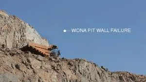
/
Final Wall Stability in Metal Open Pit Mines Using Presplit Final Wall Stability in Metal Open Pit Mines Using Presplit

Final Wall Stability in Metal Open Pit Mines Using Presplit - PowerPoint Presentation

alida-meadow
alida-meadow . @alida-meadow
Follow
398 views
Uploaded On 2016-02-21

Final Wall Stability in Metal Open Pit Mines Using Presplit - PPT Presentation

Kazem Oraee Arash Goodarzi Ali Mozafari Nikzad OraeeMirzamani Importance of presplit drilling and blasting in open pit mines slope stability study is one of the most considerable parameter for safety and economical factors of open pit mines ID: 225667

holes presplit drilling hole presplit holes hole drilling blasting buffer production spacing charge row wall pit rock burden malu

Share:

Link:

Embed:

Download Presentation from below link

Download Presentation The PPT/PDF document "Final Wall Stability in Metal Open Pit M..." is the property of its rightful owner. Permission is granted to download and print the materials on this web site for personal, non-commercial use only, and to display it on your personal computer provided you do not modify the materials and that you retain all copyright notices contained in the materials. By downloading content from our website, you accept the terms of this agreement.


Presentation Transcript

Slide1

Final Wall Stability in Metal Open Pit Mines Using Presplit Blasting

Kazem

Oraee

Arash Goodarzi

Ali Mozafari

Nikzad

Oraee-MirzamaniSlide2

Importance of presplit

drilling and blasting in open pit minesslope stability study is one of the most considerable parameter for safety and economical factors of open pit mines.

failure of mines’ walls can potentially cause loss of lives, roads blocking, damaging to mining machinery, temporarily or permanently halt production and in the worst case scenario closing the mine. Production and Mining BenefitsAbility to maintain safe conditions in mine

Increased stability of the rock wallImproved stripping ratiosReduction in ore dilutionLess broken rock to load and transportReducing the vibration level in the rock massMinimizing production schedule disturbances for mine stability comparison with mechanical rock reinforcementSlide3

Wall failure in an open pit mineSlide4

Failure in Pit Slop in Grasberg Gold Mine in Indonesia in 2003

The Grasberg mine is the largest gold mine in the

worldSlide5

Failure in Pit

Slop Angouran

Lead Mine in Iran 2006 Slide6

Wall Failure

in Pit

Slop Angouran Lead & Zinc Mine in Iran 2006 25 million tons rock slideSlide7

Pit wall stability is dependent on:

• geotechnical and hydrogeological issues

• level of design safety (based on risk assessments)• ability to secure the ground (scaling, ground support, slope dewatering)detrimental effects of blastingSlide8

drilling smaller diameter blasting holes along the final excavation boundary

drilling straight holescharging with lower explosive than main holes

firing holes in sequential timescaleGeneral Principals of Control Blasting Slide9

Controlled Blasting Methods

Line blasting

Smooth blasting Cushion blasting Presplit blastingSlide10

Presplit Hole Design

As a general guide for the presplit holes, spacing can be 8 to 12 times of the hole diameter or about

one third to less than one half of the normal spacing used in production blast holes. It also can be determined by using the following equation:S ≤ 2 rb × 2.54 × (Pb + T) / T Where S = Spacing between two presplit holes (cm)rb = Borehole radius ( cm)Pb = Borehole pressure ( Mpa)

T = Tensile strength of rock( Mpa)Slide11

In this equation borehole detonation pressure can be calculated by:

Pb = 1.69 × 10⁻³

Ye (VOD)2 (re / rb)2.6 Where Pb = Borehole pressure in psiYe = Specific gravity of explosivesVOD = Detonation velocity of explosive charge ft/s

re = Radius of explosive charge in inchesrb = Radius of borehole in inchesSlide12

Bore hole detonation pressure (P

a) for the full charge hole can be calculated by:Pd = × Ye × (VOD)

2 × 10⁶Where Pd = Detonation pressure (MPa)Ye = Density of explosive (kg/m3)VOD = Velocity of detonation (m/s)Slide13

Buffer Holes Design

(Buffer row is used to minimize blasting damage from production row to final wall)

Normally the spacing and burden of about 2/3rd of production holes are used in buffer row but if presplit and buffer rows are of same diameter then, the burden in front of the presplit row to buffer row should be 1.5 times the presplit spacing holes and in case of different diameters, then diameter of buffer holes can be set to

12 to 15 times of presplit holes diameter.As a general rule, when the diameters of production and buffer holes are the same, then the burden and spacing of the buffer row should be 70 to 80% of the production blast holes.Slide14

Hole Charge Distribution

Powder factors will normally range from

1.6 to 4.8 kg/m3The ratio of the charge diameter to hole is about 0.3 – 0.4 The specific charge recommended for presplit holes is 0.35 to 0.5 kg/m2 and generally charge factor in buffer hole is about

75% of a production holeThe charge density has to be reduced to 5 to 15 percent of the charge in production holesSlide15

Presplit Charging Methods

Air deck charging

Suspended chargingLow density chargingContinues column chargingCommon charging methods in presplit holes to minimize near field blast damageSlide16

Guidelines are offered by

Gustafsson, 1981, DuPont Hand Book, 1977, etc. which recommends the charge loads and blast hole pattern for presplitting as shown at the below table:

Hole Diameter(mm)Charge Mass / Meter of

Blast hole(kg)Cartridge Diameter(mm)

Presplit Space(m)

89

0.65

23

1.0

102

1.0

29

1.4

115

1.0

29

1.4

152

1.8

45

1.8Slide17

Shooting the Presplit Line

In order to make a free face to reflect shock wave resulted from blasting in production holes, the presplit row must be fired at least 50ms

before the main production blast. As a rule, if the presplit holes are to be detonated with production blast holes, generally 200 to 350ms (not more) of delaying interval between presplit holes and the nearest production row or buffer row is recommended.To achieve optimum presplit results, zero detonation delay (simultaneous blasting) to be used between presplit holes, although if the numbers of holes in presplit row are more than usual pattern, blasting may be done in separate groups with minimum delay in sequence.Slide18

Presplit Drilling & Blasting Key Points

• hole spacing and charging dependent on hole size, rock strength, explosive strength and decoupling ratio• highly jointed rock requires closer hole spacing than massive rock

• when firing presplit row with production row, a minimum of 200 - 350 milliseconds time delay between presplit holes and nearest production holes is recommended• use zero delays between holes to achieve optimum presplit results• a bottom charge is often used to assure that the toe is pulled• straight hole drilling is a necessitySlide19

Chador Malu

Iron Mine Site Profile Chador Malu

iron ore mine with 400 million tons of ore reserve is the biggest iron concentrate producer in Middle East, located in 180km north-east of Yazd province in central Iran. Reconnaissance for the Chador Malu deposit was first done in 1921 and more detailed work was carried out in the beginning of 1960s. Petrography studies on the mine rocks shows that major rocks in Chador Malu mine area are Metasomatite, Albitite, Diorite, Magnetite and Hematite

. The iron ore concentrate contains about 68% iron and 0.045% phosphorus. Slide20

Chador

Malu drilling fleetProduction & Buffer Hole Drilling

: DMH, DML and DM45(Rotary system) presplit Hole Drilling: Titon 600 (DTH system)Main drill patterns:Hard Rock: Burden = 6 m & Spacing = 7 mFractured Rock : Burden = 7m & Spacing = 8 m* ANFO explosive with Dynamite primers are used for blasting.Slide21

Chador Malu

iron ore mine

HoleDiameter(mm)

Sub drilling(m)

Burden(m)

Spacing

(m)

Charge Density

(

gr

/m3)

Stemming

(m)

Explosive

Bottom

Charge

(m)

Hole

Depth

(m)

Bench

Height

(m)

Hole

Angle

(degree)

251

2.25

6

7

1.0

7.25

ANFO

1

17.25

15

90

Hole Diameter

(mm)

Decoupling ratio

Buffer

Burden(m)

Buffer Spacing(m)

Charge Density(

gr

/m3)

Stemming

(m)

Explosive

Hole

depth

(m)

Hole Angle(degree)

1650341.02ANFO690

Hole Diameter(mm)Charge decoupling ratioCartridge Diameter(mm)Presplit Spacing(m)Charge Density(gr/m3)Burden(m)Time Delay(ms)Stemming & Subdrilling(m)ExplosiveHole Depth(m)Hole Angle(degree)1140.35401.451.0362000Azar Powder15.575

Drilling pattern for buffer holes at Chador Malu iron ore mine

Drilling pattern for production holes at Chador Malu iron ore mine

Drilling pattern for presplit holes at Chador Malu iron ore mineSlide22

Presplit Drilling Operation

Buffer Holes

Production Holes

presplit HolesSlide23

A schematic illustration showing drilling and blasting design in Chador

Malu mineSlide24

A schematic illustration showing of drilling profile in Chador Malu

mine Slide25

presplit Drill RigsSlide26

-Sideways: 30

°

/ 30° 30°

30°Drilling anglesSlide27

Drilling rig position for presplit drilling at Chador

Malu mineSlide28

Visual presplit evaluation

examine the presplit face and adjust spacing or chargingwith regard to:

- smoothness of presplit surface- percent of half-casts visible- occurrence of crest failuresoccurrence of plane and wedge failures in final wallSlide29

The sources of drilling deviationsSlide30

Drilling deviations in difficult condition

Designed hole direction Slide31

A schematic illustration showing sources of hole drilling deviations on mine bench

Collaring

misalignment

Collaring offset

Planed hole

In-hole deviation

Incorrect depth

Deviation due to

collar errorSlide32

Conventional Drilling Methods in Surface Mines

Top Hammer

Down the HoleCOPRODRotary

12

34Slide33

Drilling deviations depend on drilling rigsSlide34

Double Benches Drilling

Using double benches presplit blasting to reduce wall failure and achieve less total drilled meters per toneSlide35

Successful Presplit Blasting in an Open Pit Mine Slide36

Aitik Copper

Mine

The Aitik copper mine is situated in Sweden. It is one of Europe's largest open pit copper mines. Associated with the copper, large quantities of gold, silver and since 2008

molybdenum have been mined at Aitik. Slide37

Aitik Copper Mine in Sweden

Production Started

with 2 Mt/y in 1968 and now 36 Mt/yProven Reserves : 520 MtGrade: 0.31 % Copper ,0.2 gr

/t Gold & 2.0 gr/t SilverMine Life: 2025Final pit depth: 400 mProduction Holes: 311 mmW/O: 1:1 Pit Slope Design: 46 degree Bench height: 15 m

Mine SpecificationSlide38

Presplit

drilling pattern

Pre-split Holes 5 1/2 in

Production Holes 12 ¼ inBuffer Holes 6 1/2 in

16m10.5 m

15m

15m

5.0 mSlide39

Typical presplit

Drilling Design , Aitik Copper Mine in Sweden

5 ½” Pre-split holes15 m depth 22 degree incline6 ½” Buffer

holes15 m depth12 ¼” Production holes16 m depth

12 ¼” Production holes17 m depth

4.5 m

5.0 m

4.5 m

10.5 m

8.0 m

6.0 m

wallSlide40

Presplit blasting evaluation

Type

of DamageOriginCorrectionBack break around the presplit holes caused no half-casts visible in fracture lineShortage of burden or spacing in presplit line or excessive charging in buffer or presplit holesModifying burden, spacing and hole

charge densityBack break visible just around the presplit hole areaDetonation pressure in presplit holes was more than rock compression strength

Modifying hole charge density and charging methodBack

break visible just between the presplit hole area

Shortage of buffer row spacing

Increasing the spacing in buffer

row and decreasing charging density in buffer holes

Roughness and

the

irregularity of final wall behind the presplit surface

Excessive spacing or shortage of burden in presplit row

Decreasing

spacing and

hole

charge density in presplit row

Shortage of rock

breaking in final wall

Excessive burden between presplit and buffer rows

Decreasing

burden between

presplit and buffer rows

Excessive joints and cracks at f

inal wall

crest

High weathering and poor condition of final wall rock

Using

guide holes between presplit holes or drilling presplit holes with retract bit

for fracture control Slide41

Half-casts visible remained after blasting of presplit holes Slide42

Wall damages due to inappropriate spacing in presplit rowSlide43

Key Notes

Several techniques are used for improvement wall stability in open pit mines which among them, presplit blasting is the most pragmatic and effective approach for tackling this issue in metal open pit mines

The influence of geology can never be completely eliminated but certain measures can be taken to ensure acceptable blasting results such as selecting appropriate drill rig to control minimum drilling deviation on presplit rowDTH and COPROD drilling systems give less deviation than the other drilling methods thus they could be right choices for presplit drillingOrientation of geological structures has the great influence on the presplit fracture, thus, survey on structural mapping and joint sets is very important to obtain the good final wall in open pit minesVisual evaluation of presplit blasting results and modifying parameters according to mentioned table is crucial to achieve successful results.Slide44

Thanks for your kind attention