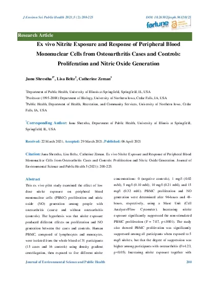
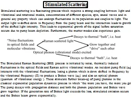
and vibrational and rotational modes concentrations of different species spin sound waves and in general any property which can undergo fluctuations in its population and couples to light ID: 412133
Download Presentation The PPT/PDF document "Stimulated scattering is a fascinating p..." is the property of its rightful owner. Permission is granted to download and print the materials on this web site for personal, non-commercial use only, and to display it on your personal computer provided you do not modify the materials and that you retain all copyright notices contained in the materials. By downloading content from our website, you accept the terms of this agreement.
Slide1
Stimulated scattering is a fascinating process which requires a strong coupling between light andvibrational and rotational modes, concentrations of different species, spin, sound waves and ingeneral any property which can undergo fluctuations in its population and couples to light. Theoutput light is shifted down in frequency from the pump beam and the interaction leads to growthof the shifted light intensity. This leads to exponential growth of the signal before saturation occurs due to pump beam depletion. Furthermore, the matter modes also experience gain.
Stimulated Scattering
The
Stimulated Raman Scattering (SRS)
process is initiated by noise, thermally
induced
fluctuations
in the optical fields and Raman active vibrational modes. An incident pump field (
ω
P
)
interacts
with the vibrational fluctuations,
losing
a photon which is down shifted
in frequency by
the
vibrational frequency
(
)
to produce a Stokes wave (
ω
S
,
)
and
also an
optical
phonon
(
quantum of vibrational energy
).
These
stimulate further break-up
of pump photons in
the
classical
exponential population dynamics process in
which “
the more you have, the more you get”.
The
pump decays with propagation distance
and both
the phonon population and Stokes
wave
grow
together. If the generation rate of Stokes
light exceeds
the loss, stimulated emission
occurs
and
the Stokes beam grows exponentially. Slide2
It is the product of optical fields which excites coherently thephonon modes. Since the “noise” requires a quantummechanical treatment here we consider only the classicalsteady state case, i.e. both the pump and Stokes are classical fields, i.e. it is assumed that both fields are present.Pump (laser) fieldStokes field,
drives
drivesSlide3
VNB: both polarizations, have exactly the correct wavevector forphase-matching to the Stokes and pump fields respectively. Also, for simplicity in theanalysis, assume that the laser and Stokes beams are collinear. However, stimulated Ramanalso occurs for non-collinear Stokes beams since is independent of .
Optical loss added
phenomenogically
→
For
g
R
I
(
p
)>
S
,
e
xponential
growth of Stokes
Phase
of Raman signal
independent of laser phase,
i.e
.
! But
if
temporal coherence of
laser is very
bad,
P
may
be larger
than
→
must average
over
P
to get
net gainSlide4
can also have gain for Stimulated Stokes in the backward direction! Get the same but boundary conditions at z=0,
L different!
In fact Stokes beam can go
in any direction
, however if the two beams are
not collinear
then the net gain is small with finite
width beams
Raman
Amplification
Optimum conversion:
When grows by one photon,
decreases
by one photon
and
of
energy
is lost
to the vibrational mode, and eventually
heat Slide5
No pump depletion (small signal gain) but with attenuation lossRaman Amplification – Attenuation, Saturation, Pump Depletion, Threshold Saturation in amplifier gain occurs due to pumpdepletion.
Assume
P
=
S
=
(reasonable approximation)
Note that the higher
the input
power
, the
faster the saturation
occurs, as expected.Slide6
Starting from noise, the Stokes seed intensity ( ) is a single “noise” photon the Stokes frequency bandwidth of the unsaturated gain profile, assumed to be Lorentzian.Mathematically for the most important case of a single mode fiber: The stimulated Raman “threshold” pump intensity is defined approximately as the input pump intensity for which the output pump intensity equals the Stokes output intensity, i.e.
A
eff
is the effective nonlinear core
area
glass
For backwards propagating Stokes
This threshold is higher than for forward
propagating Stokes. Therefore, forward
propagating Stokes goes stimulated first and
t
ypically grows so fast that it depletes the pump
so that that backwards Stokes never really growsSlide7
Raman Amplification – Pulse Walk-offStokes and pump beams propagate with different group velocities vg (S) and vg(P). The interaction efficiency is greatly reduced when
walk-off time pump pulse width
t. As a result
t
he Stokes signal spreads in time
and space
For backward propagating Stokes, the pulse
overlap is small and the amplification is weak.
Raman Laser
Threshold
condition:
Frequently
fibers used for gain.
Why? Example silica has a small
g
R
but
also an ultra-low loss allowing
long growth distances
.
For
L
10
m
,
P
P
th
=1
W
for
lasing.Slide8
Multiple Stokes and Anti-Stokes GenerationFused silica fiber excitedwith doubled Nd:YAG laser=514nm.
Spectrally resolved multiple Stokes beamsSpectrally resolved multiple Anti-Stokes
beams
To this point we have focused on terms like
which corresponded
to
What
about
,
i.e. Anti-Stokes generation? This requires tracking the
o
ptical phonon
population since a phonon must be destroyed to upshift the
frequency. Therefore
Anti-Stokes generation
follows
Stokes generation which involves the generation of the phonons.
S
P
P
ASlide9
Coherent Anti-Stokes Generation
Stimulated
Stokes;
Anti-Stokes
-
dispersion in refractive index means the waves are not collinear
for the Anti-Stokes case, similar to the CARS case discussed
previously
Thus
A
nti-Stokes
process requires phase-matching (not automatic
)Slide10
For every Stokes photon created, one pump photon is destroyed AND for every Anti-Stokes photon created another pump photon is destroyed. Also, for every Stokes photon created an optical phononis also created, and for every Anti-Stokes photon created an optical phonon is destroyedWhat is missing in the conservation of energy is the flow of mechanical energy Emech (t) into theoptical phonon modes via the nonlinear mixing interaction, and its subsequent decay (into heat).
Vibrational energy grows with the Stokes energy, and
decreases with the creation of Anti-Stokes and by
decay into heat.
If Stokes strong
2
nd
Stokes
3
rd
Stokes etc
.
Anti-Stokes is
not
automatically
wavevector
matched!
Since
Stokes
is generated in all directions
, Anti-Stokes generation
“
eats out” a
cone in
the Stokes generation (angles small
).
T
he generation of
Anti-Stokes lags
b
ehind the StokesSlide11
Stimulated Brillouin ScatteringThe normal modes involved are acoustic phonons. In contrast to optical phonons, acoustic waves travel at the velocity of sound. Light wavesFreely propagating sound waves
Forward travelling
Backwards travelling
Stimulated
Brillouin
“Noise” fluctuations
in optical fields and
sound wave fields
Brillouin
scattered light
Optical
phonon
(sound
wave)
excited
Grow
in
opposite
directions but still
“drive” each
other
Decays to
thermal
“bath”, i.e. heat
Decays to thermal
“
bath
”, i.e
. heat
Brillouin
Amplification
Stokes signal injected.Slide12
need kK for measurable S, since S0 as K 0
Backwards Stokes couples toforwards travelling phonons
For
Stokes
need
To get stimulated scattering, light and sound waves
must
be
collinear
→
Backscattering
→
K
2
k
→ phonon wave picks
up energy and grows along +
z
.
Stokes can grow along -
z
For
Anti- Stokes
need
Backwards Anti-Stokes couples
to backwards travelling phonons
backwards
phonon
wave gives
up energy
and one phonon is lost for every
anti-Stokes photon created. But the
only
backwards
phonons
available
are
due
to “noise
”
, i.e
.
k
B
T
, a very small number
! (Stokes process generates
s
ound waves in opposite direction.)
A
nti-Stokes NOT stimulated!Slide13
Stimulated RamanMolecular property Local field corrections2. Normal modes do NOT propagate.Normal mode frequency is fixed at vBoth forwards and backwards scatteringStimulated BrillouinAcousto-optics uses bulk properties NO local field corrections
2. Acoustic waves propagate.Normal mode frequency S K
4.
Backward Scattering only
Light-sound coupling
Equation
of
Motion
for
Sound Waves
Only
compressional
wave (
longitudinal acoustic
phonon
) couples to
backscattering
of light
Mass density
Acoustic
damping constant
Sound velocity
Force due to
mixing of
light beams
v
s
Gas or Liquid
Comparison between Stimulated Raman and Stimulated
BrillouinSlide14
Substituting into driven wave equation for qz
The damping of acoustic phonons at the frequencies typical of stimulated
Brillouin
(10’s GHz) frequencies is large with decay lengths less than 100
m. This limits (saturates) the growth of the phonons. In this case the phonons are damped as fast as they are created , i.e. .
Mixing of optical
beams drives
the sound wavesSlide15
Acoustic phonons modulate pump beam to produce Stokes.Power Flow (Manley Rowe)
Note that for , Q+ is linked to ES
with
S
propagates
along –
z
P
travels along +
z
Travels
and
depletes along
+
z
Travels and
grows
along
-
z
Pump beam
supplies energy for
the
Stokes
beam!Slide16
Phonon Energy Flow (need acoustic SVEA)Mixing of optical beams drives sound wavesDecay of sound waves “
heats up” the lattice
Phonon beam grows in forward direction by picking up energy from the
pump beam
. The Stokes grows in the backwards direction because it also
picks up
energy from the pump.
Exponential
Growth
W
hen the growth of the acoustic phonons is limited by their attenuation constant.
Signature of exponential growthSlide17
The energy associated with , i.e. the sound waves, eventually goes into heat.This leads to
exponential growth of Stokes along -z!!
What is happening to acoustic phonons ?
Therefore
,
acoustic damping leads to saturation of the phonon flux and exponential gain of the Stokes beam!
→In the
undepleted
pump
approximation get exponential
gain for
backwards StokesSlide18
0.20.40.60.81.0Distance z/LRelative Intensity
0.2
0.4
0.6
0.8
1.0
0.0
Pump
Stokes
For amplifying a signal
I
S
(
L
) inserted
at
z
=
L,
the growth of the signal is shown
for different signal intensities relative
to the pump intensity.
Pump signal decays
exponentially in
the forward direction as the Stokes
g
rows exponentially in the backward
direction
Assume an
isotropic solid
– the
pertinent
elasto
-optic
coefficient is
p
12
so
that
(typically 1
p
12
0.1)
.
Can add
loss
phenomenologicallySlide19
Pump Depletion and ThresholdThe analysis for no pump depletion, threshold and saturation effects is similar to that discussed previously for Raman gain effects Since S,P>>S then SP= is an excellent approximation. For no depletion of pump except
for absorption
Signal output
Brillouin
threshold
pump intensity defined as
with unsaturated
gain
& with
the
Lorentzian
line-shape for
g
B
:
To solve
analytically
for saturation which occurs in the presence of pump depletion, must
assume
=
0,
P
S
and define
Slide20
Plot of gain saturation after a propagation distanceL versus the normalized unsaturated gain GA.The higher the gain, the faster it saturates.Stimulated Brillouin has been seen in fibers at mW power levels for cw single frequency inputs. It is the dominant nonlinear effect for cw beams.e.g. fused silica : P =
1.55m, n=1.45,
vS=6
km
/
s
,
S
/2
=
11GHz
,
1/
S
17 MHz
→
g
B
5x10
-11 m/
W. This value is
500x larger the gR!
But, 1/
S
is much
smaller and requires stable single frequency input toutilize the larger gain – hence no advantage to stimulated Brillouin
for amplification.
Pulsed Pump Beam
t
P
t
S
v
g
(
P
)
v
g
(
S
)
Stokes and pump travel in opposite directions, the overlap
with a growing Stokes is very small and hence the
Stokes amplification is very small! The shorter the pump
pulse, the less Stokes is generated, i.e. this is a very
inefficient process! Stimulated Raman dominates for
pulses when pulse width <<
Ln
/c.