/
A MICROMACHINED PENDULOUS OSCILLATING GYROSCOPIC ACCELEROMETER 
... A MICROMACHINED PENDULOUS OSCILLATING GYROSCOPIC ACCELEROMETER 
...

A MICROMACHINED PENDULOUS OSCILLATING GYROSCOPIC ACCELEROMETER ... - PDF document

briana-ranney
briana-ranney . @briana-ranney
Follow
398 views
Uploaded On 2016-07-07

A MICROMACHINED PENDULOUS OSCILLATING GYROSCOPIC ACCELEROMETER ... - PPT Presentation

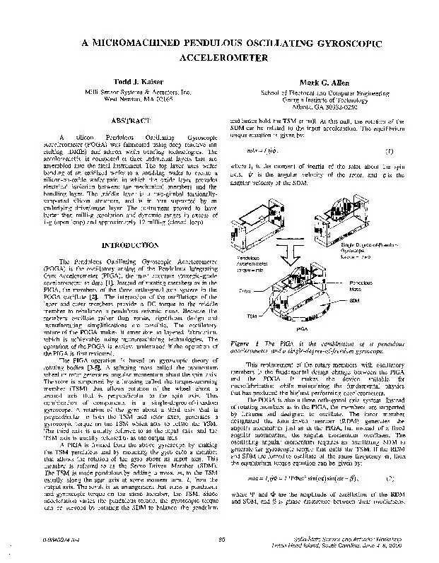
Todd J Kaiser Mark G Allen Milli Sensor Systems Actuators Inc West Newton MA 02165 School of Electrical and Computer Engineering Georgia Institute of Technology Atlanta GA 303320250 ABSTRAC ID: 394922

Todd Kaiser Mark

Share:

Link:

Embed:

Download Presentation from below link

Download Pdf The PPT/PDF document "A MICROMACHINED PENDULOUS OSCILLATING GY..." is the property of its rightful owner. Permission is granted to download and print the materials on this web site for personal, non-commercial use only, and to display it on your personal computer provided you do not modify the materials and that you retain all copyright notices contained in the materials. By downloading content from our website, you accept the terms of this agreement.


Presentation Transcript

A MICROMACHINED PENDULOUS OSCILLATING GYROSCOPIC ACCELEROMETER Todd J. Kaiser Mark G. Allen Milli Sensor Systems & Actuators, Inc. West Newton, MA 02165 School of Electrical and Computer Engineering Georgia Institute of Technology Atlanta, GA 30332-0250 ABSTRACT A silicon Pendulous Oscillating Gyroscopic Accelerometer (POGA) was fabricated using deep reactive ion etching (DRIE) and silicon wafer bonding technologies. The accelerometer is composed of three individual layers that are assembled into the final instrument. The the SDM. INTRODUCTION be-Degree-of-Freedom Gyroscope The Pendulous Oscillating Gyroscopic Accelerometer (POGA) is the oscillatory analog of the Pendulous Integrating Gyro Accelerometer (PIGA), the most accurate strategic-grade accelerometer to date [l]. Instead of rotating members as in the PIGA, the members of the three orthogonal axis system in the POGA oscillate [2]. The interaction of the oscillations of the inner and outer members Pendulous torque = II& Accelerometer torque = mla PIGA Figure 1. The PIGA is the combination of a pendulous accelerometer and single-degree-of-freedom gyroscope. The PIGA operation is based on gyroscopic theory of rotating bodies [3-q. mla = Z, I$$ = Z,Y@Wz sin(wt) sin(wt + p) , where Y and @ are the amplitude of oscillation of the RDM and SDM, and p is phase difference between their oscillations. o-9640024-3-4 85 Solid-State Sensor and Actuator Workshop Hilton Head Island, South Carolina, June 4-8, 2000 Pendulous Mass (2) IWD a=$---Jo* cosp+f(2w). The acceleration is a function of the cosine of the phase difference between the two oscillations plus a second harmonic term that time averages to zero. The phase difference becomes the control signal used to maintain the TSM at T Spin Axis Figure 2. Schematic drawing of the micromachined POGA, showing the principal components and rotational axes DEVICE DESCRIPTION The RDM of the micromachined POGA is a 4.5 mm diameter silicon member formed by etching entirely through a two inch wafer. It has two sets of four rotational electrostatic comb drives for in-plane actuation. The RDM is supported by four 50 micron wide silicon flexures that are anchored to an Figure 3. The left image shows a single RDM in an array of devices. Each RDM has a diameter of 4.5 millimeters and is formed on 6x6 mm silicon die connected by tabs. The right image is an SDM/TSM assembly with a recess for mounting the RDM m the surface. The SDM Ji-ame measures 13xZOmm. The TSM and the SDM are silicon members etched from the same 2 inch silicon wafer as a single unit. The TSM is inset within the SDM. The TSM flexures are 50 microns wide and 1 mm long connecting the TSM to the SDM. The SDM flexure dimensions are varied to match the SDM resonant frequency to the RDM resonant frequency. These flexures Figure 4. The lef image shows the base electrode configuration. The right image is cut assembled POGA: RDM mounted on TSM, SDM mounted on base, 15 n22mm. Figure 5. SEM of a quadrant of RDM. The RDM jlexure runs vertically in the image Figure 3 an RDM still in a device array on the wafer. Small tabs are left during the etching process to interconnect the components. These are easily cleaved to dice out the individual components. The second image in Figure 3 is an SDMiTSM 86 SDM sensing electrodes are positioned just inside the drive electrodes. The TSM sensing electrodes are placed under the TSM at the edge of the member to maximize sensitivity to rotations. Both sensor systems use differential capacitor readout electronics to monitor the position of the SDM and TSM. A ground plane is serpentined between the electrodes to reduce cross-talk between the capacitors. Figure 4 shows an image of the FABRICATION PROCESS The micromachined POGA is fabricated in three separate assemblies, the RDM, the SDM/TSM assembly and metal layers and the silicon mechanical layers. The wafer is then etched entirely through its thickness from the front side to define the SDM and TSM. The bases are formed in glass. Aluminum is deposited on the glass with a titanium adhesion layer. The metals are then patterned to produce the SDM drive electrodes, and the sensing electrodes for the SDM and TSM. The three components are then assembled to 7) She&w. Msk Melal Figure 6. RDM fabrication sequence. BntDrn Et* sanmn Ha!&, 61 TW Etch T/S Sllvct”rer Figure 7. SDM/TSM assembly fabrication sequence. Figure 8. Micromachined POGA assembly procedure. RESULTS Open loop, the POGA operates just like any other pendulous accelerometer. Under acceleration, the pendulous mass torques the member against the supporting flexures. This motion is detected with the differential plate capacitors for the TSM. Figure 9 shows an open loop tumble test of the bulk micromachined POGA and an ADXLlSO, an Analog Devices 87 steps through 360°, measuring the component of the earth’s gravity along the input axis of the accelerometers, -0.4 I - 2.46 0 Time (seconds) Figure 9. Open loop tumble test of ADXLISO and micromachined POGA. Rotated 10” steps at 50 second intervals measuring a component of earth’s -15 -, -1.0 I 1 I -0.5 0.0 Cosine (drive phase difference) Figure 10. Closed loop scale factor test. Input acceleration nulled by adjusting phase between input drive voltages. Closed loop, the POGA operation differs from other accelerometers. The innermost member, the RDM, generates an oscillating angular momentum. The drive frequency is set at the resonant frequency of the RDM. A bias voltage is applied to the sinusoidal signal to offset the drive so that it is always applying a positive potential to remove the frequency doubling effect of capacitive SUMMARY AND CONCLUSIONS The POGA uses the same fundamental physics that has been demonstrated to produce the highest performing accelerometer, the PIGA. The scale factor is determined only by mechanical quantities, the pendulosity and angular momentum, rather than by a precision voltage supply as in other servoed accelerometers. The fabrication methods demonstrate the use of the ICP ACKNOWLEDGMENTS Microfabrication was carried out in the Georgia Tech Microelectronics Research Center, with the assistance of the staff. The authors would also like to thank the staff of Milli Sensor Systems and Actuators for their numerous contributions as well as discussions of capacitive sensing. The authors would like REFERENCES 1. M. S. Sapwo., “Pendulous Accelerometer: POGA,” Joint Services Guidance, Navigation & Control, 24th, 1998. Oscillating Gyro Data Exchange for Anaheim, CA, Nov., 2. M. S. Sapwpo, “Pendulous Oscillating Gyro Accelerometer,” U. S. Patent #5,457,993, October 17, 1997. 3. A. Lawrence, Modern Inertial Technology, Springer- Verlag, New York, 1998. 4. G. Inertial Guidance, Wiley, New York, 1962. 5. M. Fernandez and G. R. Macomber, Inertial Guidance Engineering, Prentice-Hall, Englewook Cliffs, NJ, 1962. 6. A. Ayon, R. Braff, C. Lin, H. Sawin, and M. A. Schmidt, “Characterization of a Time Multiplexed Inductively Coupled Plasma Etcher,” J. Electrochem. Sot., Vol. 146, No. 1, pp. 339-349, 1999. 7. M. A. Schmidt, “Silicon Wafer Bonding for Micromechanical Devices,” Technical Digest of the 1994 Solid State Sensor and Actuator Workshop, Hilton Head, SC, pp127- 131, 1994. 88