/
BIFURCATEDTECHNICAL INFORMATION BIFURCATEDTECHNICAL INFORMATION

BIFURCATEDTECHNICAL INFORMATION - PDF document

briana-ranney
briana-ranney . @briana-ranney
Follow
357 views
Uploaded On 2016-05-14

BIFURCATEDTECHNICAL INFORMATION - PPT Presentation

029 2085 8200 292 AXIAL FANS 
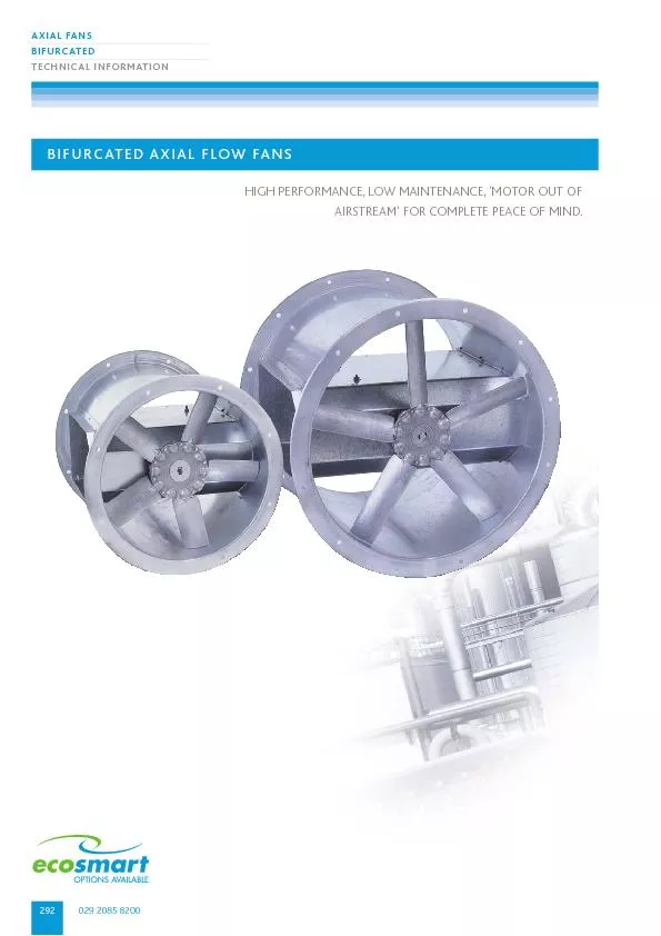
BIFURCATED AXIAL FLOW FANSHIGH PERFORMANCE LOW MAINTENANCE MOTOR OUT OFAIRSTREAM FOR COMPLETE PEACE OF MIND 029 2085 8200 300 AXIAL FANS BIFURCATEDTECHNICAL INFORMATI ID: 319472

029 2085 8200 292 AXIAL FANS BIFURCATED AXIAL

Share:

Link:

Embed:

Download Presentation from below link

Download Pdf The PPT/PDF document "BIFURCATEDTECHNICAL INFORMATION" is the property of its rightful owner. Permission is granted to download and print the materials on this web site for personal, non-commercial use only, and to display it on your personal computer provided you do not modify the materials and that you retain all copyright notices contained in the materials. By downloading content from our website, you accept the terms of this agreement.


Presentation Transcript

029 2085 8200 292 AXIAL FANS BIFURCATEDTECHNICAL INFORMATION BIFURCATED AXIAL FLOW FANSHIGH PERFORMANCE, LOW MAINTENANCE, 'MOTOR OUT OFAIRSTREAM' FOR COMPLETE PEACE OF MIND. 029 2085 8200 300 AXIAL FANS BIFURCATEDTECHNICAL INFORMATION PERFORMANCE - BIFURCATED AXIAL FLOW UNITS - 560MM Ø ELECTRICAL & SOUND Motor1 Phase(230V-50Hz)(400V-50Hz)In-duct inlet sound power levels dB re 1pWCurveUnitBladeSpeedUnitA.V.frameMotorFLCSCMotorFLCSCOctave band mid frequency HzBreakout NoCode AngleRPMkgSetsizekWampsampskWampsamps1252505001K2K 4K8KdBA@3m 560mm Ø - 4 Pole/1440rpm 1AXB56M-41*A20135043NAV2800.755.519.80.75297679919183796966 2AXB56M-42*A25135043NAV2800.755.519.80.75298475858683807261 3AXB56M-43*A30135043NAV2800.755.519.80.75297973858782807462 4AXB56M-45*A35135043NAV2800.755.519.80.75297977868983817863 5AXB56D-45*A45135043NAV2800.755.819.80.75298376878984817764 560mm Ø - 2 Pole - 2800rpm 6AXB56M-213A 20288055NAV2100---36.750919610110396898478 7AXB56M-223A25288055NAV2100---36.7508694106114102989587 8AXB56H-223A30289055NAV2112---48T23929610210397928678Notes relating to the table: The electrical and sound information in the table is nominal. Breakout dBA@3m is spherical, free field. Start currents (sc) are DOL other than for motors of 4kW and above which are Star Delta (T). *Insert number for correct phase. 1 = 1 phase, 3 = 3 phase. For ancillaries please refer to page 310. 00.511.52.533.5 - Air volume flow (m Type DAMCA 300 00.51.512.53.5 - Air volume flow (m Type DAMCA 300 560mm Ø 4 Pole/1440 rpm560mm Ø 2 Pole/2800 rpm 299 AXIAL FANS BIFURCATEDTECHNICAL INFORMATIONnuaire.co.uk Download specification from www.nuaire.co.uk/specifications PERFORMANCE - BIFURCATED AXIAL FLOW UNITS - 500MM Ø ELECTRICAL & SOUND Motor1 Phase(230V-50Hz)(400V-50Hz)In-duct inlet sound power levels dB re 1pWCurveUnitBladeSpeedUnitA.V.frameMotorFLCSCMotorFLCSCOctave band mid frequency HzBreakout NoCode AngleRPMkgSetsizekWampsampskWampsamps1252505001K2K 4K8KdBA3m 500mm Ø - 4 Pole/1440rpm 1AXB50M-41*A 20135043NAV2800.755.719.80.75298981808176686057 2AXB50M-42*A 25135043NAV2800.755.719.80.75298481808176706257 3AXB50M-43*A 30135043NAV2800.755.719.80.75299984828378716562 4AXB50M-45*A35135043NAV2800.755.721.50.75299788838479747062 500mm Ø - 2 Pole/2800rpm 5AXB50E-213A30285749NAV290---2.24.3328693979993857974 6AXB50M-213A20285749NAV290---2.24.33286939610093868174 7AXB50M-223A25285749NAV290---2.24.33289969810092868275Notes relating to the table: The electrical and sound information in the table is nominal. Breakout dBA@3m is spherical, free field. Start currents (sc) are DOL other than for motors of 4kW and above which are Star Delta (T). *Insert number for correct phase. 1 = 1 phase, 3 = 3 phase. For ancillaries please refer to page 310. 00.20.40.60.81.21.41.61.8 - Air volume flow (m Type DAMCA 300 00.51.512.53.5 - Air volume flow (m Type DAMCA 300 500mm Ø 4 Pole/1440 rpm500mm Ø 2 Pole/2800 rpm 029 2085 8200 298 AXIAL FANS BIFURCATEDTECHNICAL INFORMATION PERFORMANCE - BIFURCATED AXIAL FLOW UNITS - 450MM Ø ELECTRICAL & SOUND Motor1 Phase(230V-50Hz)(400V-50Hz)In-duct inlet sound power levels dB re 1pWCurveUnitBladeSpeedUnitA.V.frameMotorFLCSCMotorFLCSCOctave band mid frequency HzBreakout NoCode AngleRPMkgSetsizekWampsampskWampsamps1252505001K2K 4K8KdBA@3m 450mm Ø - 4 Pole/1440rpm 1AXB45M-41*A 20141032NAV2710.372.911.60.371.063.58982817871645557 2AXB45M-42*A25141032NAV2710.372.911.60.371.063.58782797873665856 3AXB45M-43*A30141032NAV2710.372.911.60.371.063.59081808075696157 4AXB45M-45*A35141032NAV2710.372.911.60.371.063.59583818175706360 450mm Ø - 2 Pole/2800rpm 5AXB45C-21*A25270038NAV2801.17.5351.12.5148697909387807469 6AXB45M-21*A20270038NAV2801.17.5351.12.5148895959789837772 7AXB45M-22*A25280038NAV290---1.53.2517.88982817871645572Notes relating to the table: The electrical and sound information in the table is nominal.Breakout dBA@3m is spherical, free field.Start currents (sc) are DOL other than for motors of 4kW and above which are Star Delta (T).*Insert number for correct phase. 1 = 1 phase, 3 = 3 phase. For ancillaries please refer to page 310. 00.250.51.01.25 - Air volume flow (m Type DAMCA 300 00.250.51.01.25 - Air volume flow (m Type DAMCA 300 450mm Ø 4 Pole/1440 rpm450mm Ø 2 Pole/2800 rpm 297 AXIAL FANS BIFURCATEDTECHNICAL INFORMATIONnuaire.co.uk Download specification from www.nuaire.co.uk/specifications PERFORMANCE - BIFURCATED AXIAL FLOW UNITS - 400MM Ø 00.20.10.40.30.50.90.81.0 - Air volume flow (m Type DAMCA 300 00.40.20.80.61.61.41.8 - Air volume flow (m Type DAMCA 300 400mm Ø 4 Pole/1440 rpm400mm Ø 2 Pole/2800 rpm ELECTRICAL & SOUND Motor1 Phase(230V-50Hz)(400V-50Hz)In-duct inlet sound power levels dB re 1pWCurveUnitBladeSpeedUnitA.V.frameMotorFLCSCMotorFLCSCOctave band mid frequency HzBreakout NoCode AngleRPMkgSetsizekWampsampskWampsamps1252505001K2K 4K8KdBA@3m 400mm Ø - 4 Pole/1440rpm 1AXB40M-41*A 20141028NAV2710.372.911.60.371.063.58579767468605053 2AXB40M-42*A 25141028NAV2710.372.911.60.371.063.58581757570615253 3AXB40M-43*A 30141028NAV2710.372.911.60.371.063.58581777671645554 4AXB40F-43*A 35141028NAV2710.372.911.60.371.063.58583787671635655 400mm Ø - 2 Pole/2800rpm 5AXB40M-21*A20270031NAV2801.17.5351.12.5148690929487797569 6AXB40M-21*A 25270031NAV2801.17.5351.12.5148796939387807469 7AXB40M-22*A 30270031NAV2801.17.5351.12.5149095949488817569Notes relating to the table: The electrical and sound information in the table is nominal. Breakout dBA@3m is spherical, free field. Start currents (sc) are DOL other than for motors of 4kW and above which are Star Delta (T).*Insert number for correct phase. 1 = 1 phase, 3 = 3 phase. For ancillaries please refer to page 310. 029 2085 8200 296 AXIAL FANS BIFURCATEDTECHNICAL INFORMATION PERFORMANCE - BIFURCATED AXIAL FLOW UNITS - 350MM Ø 00.050.150.250.350.450.550.10.20.30.50.6 - Air volume flow (m Type DAMCA 300 00.20.40.61.01.2 - Air volume flow (m Type DAMCA 300 350mm Ø 4 Pole/1440 rpm350mm Ø 2 Pole/2800 rpm ELECTRICAL & SOUND Motor1 Phase(230V-50Hz)(400V-50Hz)In-duct inlet sound power levels dB re 1pWCurveUnitBladeSpeedUnitA.V.frameMotorFLCSCMotorFLCSCOctave band mid frequency HzBreakout NoCode AngleRPMkgSetsizekWampsampskWampsamps1252505001K2K 4K8KdBA@3m 350mm Ø - 4 Pole/1440rpm 1AXB35A-41*A25143025NAV2710.372.911.60.371.063.57867666561544843 2AXB35D-41*A25143025NAV2710.372.911.60.371.063.57475707167585048 3AXB35D-42*A30143025NAV2710.372.911.60.371.063.58479747268605148 4AXB35M-45*A35143025NAV2710.372.911.60.371.063.59275757469635648 350mm Ø - 2 Pole/2800rpm 5AXB35A-21*A25281025NAV2800.553.817.10.551.365.88080838580736860 6AXB35D-21*A25281025NAV2800.553.817.10.551.365.88284918784777065 7AXB35B-22*A30281025NAV2800.553.817.10.551.365.88392888984777265Notes relating to the table: The electrical and sound information in the table is nominal. Breakout dBA@3m is spherical, free field.Start currents (sc) are DOL other than for motors of 4kW and above which are Star Delta (T). *Insert number for correct phase. 1 = 1 phase, 3 = 3 phase. For ancillaries please refer to page 310. 295 AXIAL FANS BIFURCATEDTECHNICAL INFORMATIONnuaire.co.uk Download specification from www.nuaire.co.uk/specifications PERFORMANCE - BIFURCATED AXIAL FLOW UNITS - 315MM Ø 00.050.10.150.20.250.30.350.4 Type DAMCA 300 - Air volume flow (m 00.10.20.30.50.7 - Air volume flow (m Type DAMCA 300 315mm Ø 4 Pole/1440 rpm315mm Ø 2 Pole/2800 rpm ELECTRICAL & SOUND Motor1 Phase(230V-50Hz)(400V-50Hz)In-duct inlet sound power levels dB re 1pWCurveUnitBladeSpeedUnitA.V.frameMotorFLCSCMotorFLCSCOctave band mid frequency HzBreakout NoCode AngleRPMkgSetsizekWampsampskWampsamps1252505001K2K 4K8KdBA@3m 315mm Ø - 4 Pole/1440rpm 1AXB31B-41*A25143022NAV1710.372.911.60.371.063.56772666359514643 2AXB31B-42*A30143022NAV1710.372.911.60.371.063.57176696762555046 3AXB31B-43*A35143022NAV1710.372.911.60.371.063.57479727066585349 315mm Ø - 2 Pole/2800rpm 4AXB31B-21*A25281027NAV1800.553.817.10.551.365.87281787874666155 5AXB31B-22*A30281022NAV1800.553.817.10.551.365.87685818277706558 6AXB31B-23*A35281022NAV1800.553.817.10.551.365.87988848581736861Notes relating to the table: The electrical and sound information in the table is nominal. Breakout dBA@3m is spherical, free field. Start currents (sc) are DOL other than for motors of 4kW and above which are Star Delta (T).*Insert number for correct phase. 1 = 1 phase, 3 = 3 phase. For ancillaries please refer to page 310. 029 2085 8200 294 AXIAL FANS BIFURCATEDTECHNICAL INFORMATIONDUTY RANGE - BIFURCATED AXIAL FLOW UNITS Fan Static Pressure (Pa) 300 Air volume ßow rate ( m/s 6005004000100700 800900 1000 Type DAMCA 300 Code descriptions1. Bifurcated AXUS Long cased axial2. Case diameter in cms3. Impeller specification reference4. Motor speed in poles5. Impeller blade angle reference6. Electrical supply in Phases1 = 230V, 50Hz3 = 400V, 50Hz7. Impeller materialNo letter = standard GRPA = Optional aluminium alloy8. Other options (combinations possible)T = Two speed (full and half)F = Flameproof (EExd 11BT4)C operationZ = Access door9.ES = Full Ecosmart controls. BMS interfaces and commissioning controls (as 2 & 3 below) full compatibility with Ecosmart sensors.10.B = BMS interfaces 0-10V, volt free run and fail indication. Commissioning/speed control built in.Adjustable trickle and boost if required.11.C = Commissioning/speed control built in.Adjustable trickle and boost if required.All the above control options are pre-programmed with a soft start function.The above control options are provided in a purpose made module mounted remotefrom the unit. Other controls to be specified separately see selection table.AXB 100 Z - 4 1 3 A T ES B C|||||||||||1234567891011Below is an indication of the overall duty range, a selection of which iscovered in this brochure. Please contact Nuaire (029) 20 858 200 for anyduty outside the range indicated. 293 AXIAL FANS BIFURCATEDTECHNICAL INFORMATIONnuaire.co.uk Download specification from www.nuaire.co.uk/specifications HIGH TEMPERATURE PERFORMANCE The standard bifurcated unit is suitable fortemperatures up 90ºC. High temperature optionsavailable up to 230ºC. WIDE RANGE The widest range of standard bifurcated axialsavailable. A fan to match every application ensuresmaximum efficiency saving costly energy. LOW MAINTENANCE Motor out of airstream ensures the unit is noteffected by contaminents yet is easily accessible. LONG LIFE HEAVY GAUGE GALVANISEDSTEEL CONSTRUCTION Ensures strength, durability and protection fromdamage during installation and will be corrosionresistant. TESTED TO THE HIGHEST STANDARDS Air performance to BS848 (part 1) 2007 andISO5801 (part1) 2007 with acoustic performanceto AMCA300. All carried out at our own testfacilities to ensure the most accurate performancefigures and noise data is provided, constantlymonitored to give you up to date information youcan rely on. COMPREHENSIVE ANCILLARIES Including attenuators, frequency inverters, Ecosmartcontrols and mounting ancillaries all pre-selectedfor the individual fan to ensure a perfect match andeliminate any on-site fitting problems. FAN OPTIONS Options within the bifurcated axus range, Twospeed … operation half and full, Flameproof motorsto EExd IIBT4 for operation in systems with in ductambient temp up to 230ºC. STOCK AVAILABILITY Stock range available on next day delivery.Standard products available, to give peace of mindwhen designing those rapid turnaround projects.Contact Nuaire for details. WARRANTY Bifurcated fans have a 3 year warranty. Ecosmart Bifurcated fans have a 5 year warranty. BENEFITS ANCILLARIES FOR BIFURCATED AXIAL FANS Note: individual ancillary code numbers for each fan size are included on page 310.Mounting Brackets (pair)Typical Code: CMB31Matching Flange (single)Typical Code: CMF31Flexible Connector (Single)Typical Code: CFC31Anti-Vibration Mounts (for fan only)Codes: See TablesAttenuator (standard, long andTypical Code: CA31SGuardTypical Code: CGD31Inlet ConeTypical Code: CIC31Backdraught DamperTypical Code: CBD31InvertersRefer to end of Axial section Correct method of lifting using a spreader. 317 AXIAL FANS CONTROLSTECHNICAL INFORMATIONnuaire.co.uk Download specification from www.nuaire.co.uk/specifications ELECTRONIC SPEED CONTROL (mm) Dimensions (mm) Unit CodeABCWeight Kg NSC1-3A83881800.5 NSC1-6A115951950.7 NSC1-10A115951950.7 The electronic speed controllers provide infinitely variable speed control from preset minimum to maximum. All models feature a boost start function, which appliesmaximum power to the motor for a few seconds to prevent motor stalling beforereturning to selected speed. Wiring to the motor can be either 2-wires or 3-wires controldepending on the motor design. The enclosures for ESC1-3A and ESC1-6A are rated toIP45 with the ESC1-10A rated at IP54. All controllers meet LVD and EMC directives forsafety and electromagnetic compatibility. CONTROLS CONT. ABC TRANSFORMER SPEED CONTROL (mm) Single Phase Unit CodeABCWeight Kg SPCON1.5115851801.7 SPCON3.52001402803.6 SPCON7.52001402806.0 Autotransformers having class F insulation are used to provide discrete voltage steps. All models are fitted with suitable fuses for short-circuit protection. The controller casingis manufactured from plastic pre-coated steel or impact resistant polycarbonate. Allmodels are suitable for indoor installations only. All controllers meet LVD and EMCdirectives for safety and electromagnetic compatibility. Transformer speed controlsproduce a pure sine wave output resulting in quiet motor operation.Transformer controlsare therefore preferred for noise sensitive applications. BC Code descriptions1. 3 Phase 2.Inverter Speed Control3.Output Current Rating|||123 Front View Side View Drill Pattern Drill Pattern Drill Pattern 4.8mm DIMENSIONS (MM) Frame size A inverters codes 3ISC1.2A (image shown) 3ISC1.6A (image shown) 3ISC2.1A (image shown) 3ISC3.0A (image shown) 3ISC4.0A (image shown) Frame size B inverters codes 3ISC5.9A 3ISC7.7A 3ISC10.2A Frame size C inverters codes 3ISC13.2A 3ISC15.8A 3ISC18.4A All inverters are supplied complete with integral class A filters to suppress EMCNote: Frame size A inverters are pre assembled into metal enclosures.Frame size A inverter and Drill PatternFrame size B Drill PatternFrame size C Drill Pattern 029 2085 8200 316 AXIAL FANS CONTROLSTECHNICAL INFORMATION SPEED CONTROLS TABLES Unit CodeElectronic Speed ControlUnit CodeElectronic Speed Control 1AX31X-461NSC1-3A21AX45S-481NSC1-6A 2AX31F-441NSC1-3A22AX45P-471NSC1-6A 3AX31F-451NSC1-3A23AX45P-481NSC1-6A 4AX31B-451NSC1-3A24AX45D-451NSC1-6A 5AX35D-411NSC1-3A25AX50C-411NSC1-3A 6AX35X-421NSC1-3A26AX50D-411NSC1-6A 7AX35F-431NSC1-3A27AX50P-411NSC1-6A 8AX35F-441NSC1-3A28AX50P-421NSC1-6A 9AX35F-451NSC1-3A29AX50S-45*NSC1-10A 10AX40D-411NSC1-3A30AX56B-411NSC1-3A 11AX40I-411NSC1-3A31AX56F-411NSC1-6A 12AX40I-421NSC1-3A32AX56S-42*NSC1-10A 13AX40I-431NSC1-6A33AX63F-411NSC1-6A 14AX40I-441NSC1-6A34AX710-611NSC1-6A 15AX40I-451NSC1-6A35AX710-621NSC1-6A 16AX45S-411NSC1-3A36AX71P-621NSC1-6A 17AX45P-411NSC1-3A37AX71AA-621NSC1-6A 18AX45S-431NSC1-6A38AX80O-611NSC1-6A 19AX45S-451NSC1-6A39AX80O-621NSC1-6A 20AX45S-471NSC1-6A40AX80P-621NSC1-6A* refers to code 1 or 3 phase.CONTROLS DIMENSIONS (mm) & WEIGHTS Fan codeA B C Weight KgDrillPattern D mmE mm ES-ISC1.2A230325 4106340298 ES-ISC2.4A230325 4106340298 ES-ISC3.3A2303254106340298 ES-ISC4.1A2303254106340298 ES-ISC5.6A29039045514470373 ES-ISC7.3A29039045514470373 ES-ISC8.8A29039045514470373 ES-ISC12.5A29039045520470373 ES-ISC15.6A29039045520470373 ES-ISC23.1A29039045520470373 ES-ISC38.0A35552580540710510The Ecosmart Energy Saving Speed Control is designed to control selected Nuaire fansand to match the range of integrated Ecosmart control systems. The control is onlyavailable for three phase electrical supply.The case material is of Aluzinc corrosion resistant steel, incorporates a frequency inverter,Ecosmart control board and is directly compatible with the Ecosmart range of usercontrols, time clocks, stats and sensors. Code descriptions1. ES = Ecosmart 2.Inverter Speed Control3.Output Current RatingES- ISC 2.4A |||123 ACD2D2BDE Internal mountingPlease note: € Select a control by matching the unit full load current with the control code i.e. controlcode ES-ISC3.3A is suitable for a fan with a maximum full load current of 3.3A. TheInverter overload is pre-set at the rating plate value, if a lower setting is required fit anappropriately sized overload relay or adjust inverter settings. € The mains power supply to the controller must be appropriately sized and installed via alocal isolation switch (by others). The isolator must also accommodate the 230V switched live (if used). The mains supplyfrom the Ecosmart controller to the fan must be appropriately sized, not exceeding 30metres and must be a screened power cable, earthed at both ends. A four point glanding plate is formed from the base of the control and in order tomain EMC compliance, EMC glanding kit is supplied. € Not suitable for contra rotating/run and standby axial units. € All integrated sensors plug directly into the control panel. € Refer to product datasheet No. 671432 for further information. 315 AXIAL FANS BIFURCATED UNIT WIRINGTECHNICAL INFORMATIONnuaire.co.uk Download specification from www.nuaire.co.uk/specifications BIFURCATED WIRING U2 U1 (Not speed controllable) 230V 1 phase terminal box Supply LN Single Speed 1 phase Three PhaseSupply U1 W1 terminal box 400V 3 phase 50HZ supply Single Speed 3 phase (below 4kW) U1V1W1W2U2V2 400V 3 phase 50Hz supply STARL2 - V1L3 - W1Link W2, U2, V2DELTAL1 - U1 - W2L2 - V1 - U2 L3 - W1 - V2 For D.O.L (Direct On Line Starting) operation or Inverter type Speed Control, wire in DELTA 3 phase for STAR /DELTA STARTING (4kW and above) U1V1W1W2U2V2 400V 3 phase 50Hz supply L1L2L3 3 phase for DOL STARTING(4kW and above) 400V 3 phase 50HZ supply 1U1V1W2U2V2W boxNOTE:LOW SPEED - Supply: 1U 1V 1WSupply: 2U 2V 2W Note: individual wiring instructions are included with each unit 2 Speed TAP/PAM Wound Motor(D.O.L.starting both speeds) L1 L/L2 N/L3 PE/ W V U 400V 3 phase 50Hz supply Connections 3 Phase input Motor3 phase Matched Nuaire Inverter Speed Control 313 AXIAL FANS TECHNICAL INFORMATIONnuaire.co.uk Download specification from www.nuaire.co.uk/specifications CIRCULAR ATTENUATORSStandard Podded PERFORMANCE, DIMENSIONS (mm)& WEIGHTS Dynamic AttenuationOctave band mid frequency (Hz)Dimensions & Weights Dia.Unit CodeType1252505001K2K4K8KACDEFGWeight KgZ 250mmCA25SPStandard - Podded-2-5-13-16-17-11-82504502504M83008.0 82 315mmCA31SPStandard - Podded-3-6-14-16-17-11-83155153158M835512.0 26.6 350mmCA35SPStandard - Podded-3-6-14-17-17-11-83555553558M839517.0 19.7 400mmCA40SPStandard - Podded-3-7-14-18-16-11-84006004008M1045023.0 8.2 450mmCA45SPStandard - Podded-4-7-15-18-16-11-84506504508M1050030.0 6.2 500mmCA50SPStandard - Podded-4-8-15-19-15-11-850070050012M1056033.0 4.0 560mmCA56SPStandard - Podded-5-8-16-21-14-11-856076056012M1062037.0 2.7 630mmCA63SPStandard - Podded-5-8-16-21-14-11-863083063012M1069044.0 1.5 710mmCA71SPStandard - Podded-6-9-17-20-14-11-971091071016M1077050.0 0.9 800mmCA80SPStandard - Podded-6-9-18-18-14-11-9800100080016M10860105.0 0.55 900mmCA90SPStandard - Podded-7-10-19-17-15-11-10900110090016M12970132.0 0.31 1000mmCA100SPStandard - Podded-7-11-19-17-14-11-1010001200100016M121070160.0 0.22 1120mmCA112SPStandard - Podded-8-12-20-17-13-11-1011201320112020M121190206.0 0.13 1250mmCA125SPStandard - Podded-8-12-20-17-13-11-1012501450125020M121320269.0 0.08 Long Podded PERFORMANCE, DIMENSIONS (mm)& WEIGHTS Dynamic AttenuationOctave band mid frequency (Hz)Dimensions & Weights Dia.Unit CodeType1252505001K2K4K8KACDEFGWeight KgZ 250mmCA25LPLong - Podded-4-10-21-27-29-19-125004502504M830016.0 82 315mmCA31LPLong - Podded-5-10-23-27-29-19-136305153158M835522.0 26.6 350mmCA35LPLong - Podded-5-11-23-28-29-20-147105553558M839531.0 19.7 400mmCA40LPLong - Podded-6-11-24-29-27-20-158006004008M1045043.0 8.2 450mmCA45LPLong - Podded-6-12-24-30-27-21-159006504508M1050055.0 6.2 500mmCA50LPLong - Podded-7-12-25-32-26-21-17100070050012M1056061.0 4.0 560mmCA56LPLong - Podded-8-13-26-34-25-22-18112076056012M1062068.0 2.7 630mmCA63LPLong - Podded-8-13-26-34-25-22-18126083063012M1069080.0 1.5 710mmCA71LPLong - Podded-9-14-27-32-25-21-18142091071016M1077091.0 0.9 800mmCA80LPLong - Podded-10-15-29-30-25-20-171600100080016M10860191.0 0.55 900mmCA90LPLong - Podded-11-16-31-29-25-20-171800110090016M12970241.0 0.31 1000mmCA100LPLong - Podded-12-17-32-29-23-19-1720001200100016M121070291.0 0.22 1120mmCA112LPLong - Podded-14-18-33-29-22-18-1622401320112020M121190373.0 0.13 1250mmCA125LPLong - Podded-14-18-33-29-22-18-1625001450125020M121320490.0 0.081Note: Air pressure drop of attenuator (Pa) = Z x Qwhere Z = Factor listed in table above Q = air volume flow rate (m/ C 'E' No. of holes tapped 'F' equi-spaced on 'G' P.C.D. 029 2085 8200 312 AXIAL FANS TECHNICAL INFORMATION IN-LINE CIRCULAR ATTENUATORSStandard Un-podded PERFORMANCE, DIMENSIONS (mm)& WEIGHTS Dynamic AttenuationOctave band mid frequency (Hz)Dimensions & Weights Dia.Unit CodeType1252505001K2K4K8KACDEFGWeight Kg 250mmCA25SStandard Un-podded-1-2-4-7-9-7-52504502504M83006.0 315mmCA31SStandard Un-podded-1-2-4-7-9-7-53155153158M83558.0 350mmCA35SStandard Un-podded-1-2-4-7-9-7-53555553558M839511.0 400mmCA40SStandard Un-podded-2-3-5-7-9-6-54006004008M1045016.0 450mmCA45SStandard Un-podded-2-3-6-7-8-6-54506504508M1050020.0 500mmCA50SStandard Un-podded-2-3-6-8-8-6-450070050012M1056023.0 560mmCA56SStandard Un-podded-2-4-7-8-8-5-456076056012M1062025.0 630mmCA63SStandard Un-podded-2-4-8-9-8-5-463083063012M1069030.0 710mmCA71SStandard Un-podded-3-5-8-9-7-5-471091071016M1077034.0 800mmCA80SStandard Un-podded-3-5-9-8-7-4-3800100080016M1086073.0 900mmCA90SStandard Un-podded-3-6-9-8-6-4-2900110090016M1297092.0 1000mmCA100SStandard Un-podded-3-6-9-8-6-4-210001200100016M121070111.0 1120mmCA112SStandard Un-podded-4-6-9-7-6-3-211201320112020M121190143.0 1250mmCA125SStandard Un-podded-4-7-9-7-5-3-212501450125020M121320188.0Note: Pressure drop negligible. Long Un-podded PERFORMANCE, DIMENSIONS (mm)& WEIGHTS Dynamic AttenuationOctave band mid frequency (Hz)Dimensions & Weights Dia.Unit CodeType1252505001K2K4K8KACDEFGWeight Kg 250mmCA25LLong - Un-podded-2-3-6-12-15-13-95004502504M830011.0 315mmCA31LLong - Un-podded-2-3-6-12-15-13-96305153158M835515.0 350mmCA35LLong - Un-podded-2-3-6-12-15-12-87105553558M839521.0 400mmCA40LLong - Un-podded-3-3-7-13-14-12-88006004008M1045030.0 450mmCA45LLong - Un-podded-3-4-8-13-14-11-79006504508M1050038.0 500mmCA50LLong - Un-podded-3-4-10-14-13-10-7100070050012M1056042.0 560mmCA56LLong - Un-podded-3-5-12-14-13-10-7112076056012M1062047.0 630mmCA63LLong - Un-podded-3-6-13-15-13-9-6126083063012M1069056.0 710mmCA71LLong - Un-podded-4-6-13-15-12-9-6142091071016M1077063.0 800mmCA80LLong - Un-podded-4-8-14-14-11-8-51600100080016M10860133.0 900mmCA90LLong - Un-podded-5-10-15-14-10-6-31800110090016M12970166.0 1000mmCA100LLong - Un-podded-6-11-15-14-10-6-320001200100016M121070203.0 1120mmCA112LLong - Un-podded-6-11-15-13-10-6-322401320112020M121190261.0 1250mmCA125LLong - Un-podded-6-12-15-12-9-5-325001450125020M121320343.0 Note: Pressure drop negligible. C 'E' No. of holes tapped 'F' equi-spaced on 'G' P.C.D. Attenuators and Pods (when fitted) shall be rigidly constructed fromgalvanised steel, internally lined with sound absorbing material not lessthan 100mm thick retained by galvanised steel perforated sheet.Attenuator end faces shall be drilled and tapped to match the flangedetails of the associated fan.Attenuator sound absorbing material shall be chemically inert, non-combustible, non-hydroscopic and vermin resistant.Attenuator shall be tested in accordance with BS4718:1971 ASTME 477.Application: All attenuators shall be suitable for internal and external use at any installed angle.Note: Podded attenuators with higher acoustic performance and otherspecifications are available. Please contact Nuaire Technical for details. 311 AXIAL FANS TECHNICAL INFORMATIONnuaire.co.uk Download specification from www.nuaire.co.uk/specifications Anti Vibration Mountings Supplied as a set of 4. To select match isolated assembly weight to maxSupporting weight shown on right. Typical code: NAV1- Resilient Rubber NAV49 - Spring type. DIMENSIONS (mm)& WEIGHTS Max Supporting CodeTypeBCWeight Kg NAV1Rubber305020.0 NAV2Rubber407580.0 NAV3Rubber4075180.0 NAV4Rubber4075260.0 NAV5Rubber4075130.0 NAV6Rubber50100320.0 NAV49Spring7776400.0 NAV50Spring7776480.0 NAV51Spring7776520.0 NAV52Spring87127600.0 NAV53Spring87127700.0 NAV54Spring87127800.0 NAV55Spring87127950.0 NAV56Spring871271110.0 NAV57Spring871271270.0 NAV58Spring871271430.0 B B B NAV1-5Resilient RubberNAV6Resilient RubberNAV49-58Spring ANCILLARIES FOR AXIAL FANS - DETAILS CONT. TABLE 1 DIMENSIONS (mm)& WEIGHTS InletB/draughtGuardconeDamper FanØABCDEF GHWeight KgWeight KgWeight Kg 250mm65150350350853551701500.41.56 310mm65150350350854052102200.527.5 350mm6515035035090460240250129 400mm65150350350905202702901.5311 450mm65150350350905803003301.7414 500mm651503503501006503403802.3516.5 560mm651503503601007003704202.8620 630mm651503504001308304305003.2922.5 710mm651503504401709204705403.71127.5 800mm65150350470200105054059041335 900mm65150350520220118060067072055 1000mm65150350580230130067077072366.5 1120mm65150350920260145075087083280 1250mm65150350985300160083092084088 029 2085 8200 310 AXIAL FANS TECHNICAL INFORMATIONMounting Brackets The AXUS mounting brackets are manufactured from heavy gaugegalvanised steel and are supplied in pairs. (See table 1 for dimensions).Typical Code: CMB100(100 = fan diameter in cm). fixing centres C/L fan Matching Flange (Single) Manufactured from galvanised steel matching flanges are suppliedindividually. (See table 1 for dimensions and weights).Typical code: CMF100(100 = fan diameter in cm). A Holes matchfan flanges Flexible Connector (Single) Circular without flanges. Flexible duct material is flameproof and resistantto heat up to 132°C/400°C, chemicals, ozone, oil and grease. The materialis airtight, waterproof and tested to BS476 Part 7.(See table 1 for dimensions and weights).(Supplied complete with fixing straps).Typical Code: CFC100(100 = fan diameter in cm) - 132°C.CFCH100 (100 = fan diameter in cm) - 400°C. BTo matchfan diameter Guard (Single) Manufactured from heavy gauge galvanised steel and acid zinc plated (See table 1 for dimensions and weights). Standard Accessory Losses (k).Flat type € Finger guard 0.4.Typical Code: CGD100(100 = fan diameter in cm) Pressure Drop (Pa) = 0.6 x k x Velocity (m/s). Inlet Cone (Single) Manufactured in heavy gauge galvanised steel with a single bolted flange. (See table 1 for dimensions and weights). Standard Accessory Losses (k).Low loss € inlet cone 0.38.Typical Code: CIC100(100 = fan diameter in cm) Pressure Drop (Pa) = 0.6 x k x Velocity (m/s). Backdraught Damper (Single) Gravity operated backdraught damper, manufactured from heavy gaugegalvanised steel with a pair of bolted flanges. (See table 1 for dimensions and weights). Standard Accessory Losses (k) (Air stream operated) 0.4Typical Code: CBD100 (100 = fan diameter in cm) - 132°C (For horizontal mounting only).Pressure Drop (Pa) = 0.6 x k x Velocity (m/s). C D Holes matchfan flanges ANCILLARIES FOR AXIAL FANS - DETAILS 309 AXIAL FANS TECHNICAL INFORMATIONnuaire.co.uk Download specification from www.nuaire.co.uk/specifications ANCILLARIES BIFURCATED AXIAL FANS AncillaryCodeAXB31AXB35AXB40AXB45AXB50AXB56AXB63AXB71AXB80AXB90AXB100 (mm) 315 350 400 450 500 560 630 710 8009001000 DescriptionMounting brackets CMB31CMB35CMB40 CMB45 CMB50CMB56 CMB63 CMB71CMB80CMB90CMB100Bracketssupplied as pair.manufactured fromheavy gauge steel. Matching Flange supplied as single. CMF31 CMF35 CMF40 CMF45 CMF50 CMF56 CMF63 CMF71 CMF80CMF90CMF100FlangeManufactured fromgalvanised steel. FlexibleCircular without flange. CFC31 CFC35 CFC40 CFC45 CFC50 CFC56 CFC63 CFC71 CFC80CFC90CFC100ConnectorFlexible duct material is flameproof and heat resistant up to 132C. The material is airtight and waterproof. Anti-vibrationResiliant rubber, forsfan only. AttenuatorStandard, Long, CA31S CA35S CA40S CA45S CA50S CA56S CA63S CA71S CA80SCA90SCA100Spodded & long CA31L CA35L CA40L CA45L CA50L CA56L CA63L CA71L CA80LCA90LCA100Lpodded options.CA31P CA35P CA40P CA45P CA50P CA56P CA63P CA71P CA80PCA90PCA100PCA31LP CA35LP CA40LP CA45LP CA50LP CA56LP CA63LP CA71LP CA80LPCA90LPCA100LP GuardManufactured in heavy CDG31 CDG35 CDG40 CDG45 CDG50 CDG56 CDG63 CDG71 CDG80 CDG90CDG100gauge galvanised steel Inlet Conemanufactured in heavy CIC31 CIC35 CIC40 CIC45 CIC50 CIC56 CIC63 CIC71 CIC80CIC90 CIC100 gauge galvanised steelwith a single bolted flange. BackdraftGravity operated damper CBD31 CBD35 CBD40 CBD45 CBD50 CBD56 CBD63 CBD71 CBD80CBD90 CBD100 manufactured fromheavy gauge galvanisedflanges. ControlsChoice of Inverter. For further details on AV Mounts please contact NuaireFor further details on Controls please contact Nuaire See page 310 for ancillaries 029 2085 8200 308 AXIAL FANS TECHNICAL INFORMATION AXUS AXIAL FANS AncillaryCodeAX25AX31AX35AX40AX45AX50AX56AX63AX71AX80AX90AX100AX112AX125 (mm) 250 315 350 400 450 500 560 630 710 800900100011201250 DescriptionMounting brackets CMB25 CMB31CMB35CMB40 CMB45 CMB50CMB56 CMB63 CMB71CMB80CMB90CMB100CMB112CMB125Bracketssupplied as pair.manufactured fromheavy gauge steel. Matching Flange supplied as single. CMF25 CMF31 CMF35 CMF40 CMF45 CMF50 CMF56 CMF63 CMF71 CMF80CMF90CMF100CMF112CMF125FlangeManufactured fromgalvanised steel. FlexibleCircular without flange. CFC25 CFC31 CFC35 CFC40 CFC45 CFC50 CFC56 CFC63 CFC71 CFC80CMC90CMC100CMC112CMC125ConnectorFlexible duct material is flameproof and heat resistant up to 132C. The material is airtight and waterproof. Anti-vibrationResiliant rubber, forsfan only. Acoustic JacketAcoustic materialfoam. Complete withstraps/buckles for security. AttenuatorStandard, Long, CA25S CA31S CA35S CA40S CA45S CA50S CA56S CA63S CA71S CA80SCA90SCA100SCA112SCA125Spodded & long CA25L CA31L CA35L CA40L CA45L CA50L CA56L CA63L CA71L CA80LCA90LCA100LCA112LCA125Lpodded options.CA25P CA31P CA35P CA40P CA45P CA50P CA56P CA63P CA71P CA80PCA90PCA100PCA112PCA125PCA25LP CA31LP CA35LP CA40LP CA45LP CA50LP CA56LP CA63LP CA71LP CA80LPCA90LPCA100LPCA112LPCA GuardManufactured in heavy CDG25 CDG31 CDG35 CDG40 CDG45 CDG50 CDG56 CDG63 CDG71 CDG80 CDG90CDG100CDG112CDG125gauge galvanised steel Inlet Conemanufactured in heavy CIC25 CIC31 CIC35 CIC40 CIC45 CIC50 CIC56 CIC63 CIC71 CIC80CIC90 CIC100 CIC112 CIC125gauge galvanised steelwith a single bolted flange. BackdraftGravity operated damper CBD25 CBD31 CBD35 CBD40 CBD45 CBD50 CBD56 CBD63 CBD71 CBD80CBD90 CBD100 CBD112 CBD125manufactured fromheavy gauge galvanisedflanges. ControlsChoice of Inverter,electronic or transformerspeed controls available. ANCILLARIES For further details on Acoustic Jackets please contact NuaireFor further details on AV Mounts please contact NuaireFor further details on Controls please contact Nuaire See page 310 for ancillaries 307 AXIAL FANS BIFURCATEDTECHNICAL INFORMATIONnuaire.co.uk Download specification from www.nuaire.co.uk/specifications FAN SPECIFICATION The ventilation fan Unit shall be configured and arranged as detailed on thedrawings and in accordance with the schedule of equipment and shall be of theAXUS Bifurcated (AXB) axial flow fan as manufactured by Nuaire, with motorout of the airstream. The units shall be manufactured from galvanised steel toBS EN10142 1991. Wiring must be direct to the motor terminal box by thecontractor.The fan impeller and motor shall be selected to provide the most energyefficient solution conforming to part L regulations and shall be direct drive withIE2 high efficiency motors to BS5000 as standard and shall be foot mountedTEFV type with IP55 enclosures and class F insulation in accordance withBS4999 part 20. They shall have sealed for life ball bearings. Motors shall be pre-wired to an external electrical terminal box through weatherproof flexibleconduit to IP55. The units shall be suitable for operation in airstream temperatures up to 90°C.Optional high temperature versions are suitable in airstream temperatures of upto 230°C.The impeller blades shall be of special aero-foil section giving excellentperformance and low noise characteristic manufactured from cast aluminiumalloy. All units shall be suitable for internal and external operation and can beinstalled any angle.The units will be provided complete with matching flanges, flexible connections,anti vibration mounts and all other necessary components to complete theinstallation and shall be in accordance with the manufacturers specification.The contractor shall allow for all necessary ductwork transformations to andfrom the fan unit and any associated components in accordance with themanufacturers recommendations, DW 144 and general good practice. CONTROL SPECIFICATION The fan unit shall be supplied with one of the following control options (onlyavailable for three phase fan units):- 1. ECOSMART CONTROLS The compact Ecosmart control system complete with all necessary controls tofacilitate the operation of the ventilation system. It shall be come complete withan integral factory fitted Ecosmart PCB which will control the fan unit within thedesired design parameters and provide the interface between all external controldevices and the unit itself. The fan unit shall have the following energy saving components integrallymounted, pre-wired to interface with the purpose made PCB, all componentspre-wired, configured and factory fitted by the manufacturer: - € Integral Frequency inverter/speed controller. € Integral maximum and minimum speed adjustment for commissioning. € Integral adjustable run on timer. € Integral BMS interfaces … 0-10V speed adjustment. € Integral BMS interfaces … Volt free failure and status indication. € Integral background ventilation switch (trickle switch). € Multiple IDC sockets for interconnection of sensors or fans using pre-plugged4-core low voltage cable. ECOSMART SYSTEM OPERATION The Ecosmart controls will enable the unit to automatically vary its speed as itreceives signals from one of the interconnected sensors. When the signal isreceived the fan shall either increase speed gradually until the required level isachieved or it will work on a trickle and boost principle. This will then move thefan duty point from trickle/background ventilation rate to the required boostventilation rate. Both the trickle and boost rates are infinitely variable, easy toadjust and remove the need of a main balancing damper. 2. BMS INTERFACES The fan unit shall be provided with the following integrated BMS interfaces. € 0 - 10 volt contacts to provide a full BMS interface. This will enable thefollowing functions:-Switch the unit on/off.Switch from low speed to high speed.Full speed control facility. € 2 No. Volt free contacts to provide fan run and failure indication to providesystem status. € An integrated commissioning/speed control to accurately commission thesystem, with minimum and maximum speeds easily adjusted via a miniaturedial, as recommended in Part L. This will enable the unit to be configured to runbetween set parameters thus saving motor power and limiting noise. 3. COMMISSIONING SET UP The fan unit shall be provided with an integrated commissioning/speed controlto accurately commission the system, as recommended in Part L, minimum andmaximum speeds easily adjusted via miniature dial. The commissioning set upfacility directly controls the integrated speed control/frequency inverter. 4. STANDARD CONTROLS The unit shall be provided with a standard speed control or starter in accordancewith the manufacturers recommendations.Bifurcated fans have a 3 year warranty. Ecosmart Bifurcated fans have a 5 year warranty.All equipment shall be as manufactured by Nuaire Ltd. CONSULTANTS SPECIFICATION 029 2085 8200 306 AXIAL FANS BIFURCATEDTECHNICAL INFORMATION DIMENSIONS - AXUS BIFURCATED AXIAL FAN DIMENSIONS (mm)& WEIGHTS Max. CodeABCDEFGHJKWeight Kg AXB3131540050021042081235522027022 AXB3535043050024042081239525030025 AXB4040049053027045081245029034031 AXB4545054053030045081250033038038 AXB50500608605340525121256038043049 AXB56560670605370525121262042047055 AXB63630740630430550121269050055084 AXB717107957004706201612770540600153 AXB808008859505408701612860590650257 AXB9090010009506008701615970670750307 AXB1001000110095067084016151070770850414 F= No. of G dia on H p.c.d. Unit shown supported on brackets and A.V. mounts OptionalAV mounts AIRFLOW E ctrs B Flange K foot J ctrs 305 AXIAL FANS BIFURCATEDTECHNICAL INFORMATIONnuaire.co.uk Download specification from www.nuaire.co.uk/specifications PERFORMANCE - BIFURCATED AXIAL FLOW UNITS - 1000MM Ø 4681012 200250300 - Air volume flow (m resistance to airflow (Pa)(Unpodded negligible) Type DAMCA 300 5.07.512.515.0 22.5400500600 - Air volume flow (m resistance to airflow (Pa)(Unpodded negligible) Type DAMCA 300 1000mm Ø 6 Pole/920 rpm1000mm Ø 4 Pole/1440 rpm ELECTRICAL & SOUND Motor3 Phase(400V-50Hz)In-duct inlet sound power levels dB re 1pWCurveUnitBladeSpeedUnitA.V.frameMotorFLCSCOctave band mid frequency HzBreakout NoCode AngleRPMkgSetsizekWampsamps1252505001K2K 4K8KdBA3m 1000mm Ø - 6 Pole/920rpm 1AXB100LF-613A10945258NAV41122.25.923.68589929289867768 2AXB100LF-623A15950287NAV613236.639.68692929087847567 3AXB100LF-633A20960299NAV613249T16.28794938985837268 4AXB100LF-643A25950299NAV61325.512.3T21.59195939086847668 5AXB100LF-653A30970371NAV491607.516T36.89595949187857969 6AXB100LF-663A35970371NAV491607.516T36.810298959389868071 1000mm Ø - 4 Pole/1440rpm 7AXB100LF-413A101440299NAV61327.514.5T34.8949810110198958777 8AXB100LF-423A151460351NAV491601120T40.0951011019996948477 9AXB100LF-433A201460351NAV491601120T40.0961031029894928177 10AXB100LF-443A251465371NAV491601527T65.01001041039995938578 11AXB100LF-453A301465414NAV5018018.534T71.410410510310096948879Notes relating to the table:The electrical and sound information in the table is nominal. Breakout dBA@3m is spherical, free field. Start currents (sc) are DOL other than for motors of 4kW and above which are Star Delta (T). For ancillaries please refer to page 310. 029 2085 8200 304 AXIAL FANS BIFURCATEDTECHNICAL INFORMATION PERFORMANCE - BIFURCATED AXIAL FLOW UNITS - 900MM Ø ELECTRICAL & SOUND Motor3 Phase(400V-50Hz)In-duct inlet sound power levels dB re 1pWCurveUnitBladeSpeedUnitA.V.frameMotorFLCSCOctave band mid frequency HzBreakout NoCode AngleRPMkgSetsizekWampsamps1252505001K2K 4K8KdBA@3m 900mm Ø - 6 Pole/920rpm 1AXB90LF-613A10920200NAV4901.14.311.68390919186848167 2AXB90LF-623A15945214NAV41122.25.923.68692939287848168 3AXB90LF-633A20945214NAV41122.25.9T23.68894969387858271 4AXB90LF-653A30960255NAV413249T16.29396959386827970 900mm Ø - 4 Pole/1440rpm 5AXB90LF-413A101420214NAV411248.4T18.5939910010096949176 6AXB90LF-423A151440243NAV41325.510.7T25.79510210310196949178 7AXB90LF-433A201440255NAV41327.514.5T34.89710410510397949180 8AXB90LF-453A301460307NAV61601120T40.010310510410295928879Notes relating to the table:The electrical and sound information in the table is nominal. Breakout dBA@3m is spherical, free field.Start currents (sc) are DOL other than for motors of 4kW and above which are Star Delta (T). For ancillaries please refer to page 310. 345 100150200250 7300 89 - Air volume flow (m resistance to airflow (Pa)(Unpodded negligible) Type DAMCA 300 4681012 300400500 14700 - Air volume flow (m Podded attenuatorresistance to airflow (Pa)(Unpodded negligible) Type DAMCA 300 900mm Ø 6 Pole/920 rpm900mm Ø 4 Pole/1440 rpm 303 AXIAL FANS BIFURCATEDTECHNICAL INFORMATIONnuaire.co.uk Download specification from www.nuaire.co.uk/specifications PERFORMANCE - BIFURCATED AXIAL FLOW UNITS - 800MM Ø ELECTRICAL & SOUND Motor1 Phase(230V-50Hz)(400V-50Hz)In-duct inlet sound power levels dB re 1pWCurveUnitBladeSpeedUnitA.V.frameMotorFLCSCMotorFLCSCOctave band mid frequency HzBreakout NoCode AngleRPMkgSetsizekWampsampskWampsamps1252505001K2K 4K8KdBA@3m 800mm Ø - 6 Pole/960rpm 1AXB80LF-611A10960143NAV3800.372.911.6---7382838480756663 2AXB80LF-623A15960147NAV390---1.14.311.67585848379756762 3AXB80LF-633A20960147NAV390---1.14.311.67789848379766862 4AXB80LF-643A25960152NAV3112---2.25.923.68088858379766863 5AXB80LF-653A30960152NAV3112---2.25.923.68487878479756964 6AXB80LF-663A35960193NAV4132---36.435.28689878580767165 7AXB80LF-673A40960193NAV4132---36.435.28891888680777266 800mm Ø - 4 Pole/1440rpm 8AXB80LF-413A101420147NAV390---1.53.618.98692979692878072 9AXB80LF-423A151430152NAV3100---36.842.88692979592888172 10AXB80LF-433A201420164NAV3112---48.4T18.58792979491888271 11AXB80LF-443A251440193NAV4132---5.510.7T25.79195989591888372 12AXB80LF-453A301440205NAV4132---7.514.5T34.89498989691888473 13AXB80LF-463A351460257NAV4160---1120T40.0100100999793898674 14AXB80LF-473A401460257NAV4160---1120T40.01051021009894908976Notes relating to the table:The electrical and sound information in the table is nominal. Breakout dBA@3m is spherical, free field.Start currents (sc) are DOL other than for motors of 4kW and above which are Star Delta (T). For ancillaries please refer to page 310. 023420406080100 120140160 200 78 - Air volume flow (m resistance to airflow (Pa)(Unpodded negligible) Type DAMCA 300 4681012 350400450 - Air volume flow (m resistance to airflow (Pa)(Unpodded negligible) Type DAMCA 300 800mm Ø 6 Pole/960 rpm800mm Ø 4 Pole/1440 rpm 029 2085 8200 302 AXIAL FANS BIFURCATEDTECHNICAL INFORMATION PERFORMANCE - BIFURCATED AXIAL FLOW UNITS - 710MM Ø ELECTRICAL & SOUND Motor1 Phase(230V-50Hz)(400V-50Hz)In-duct inlet sound power levels dB re 1pWCurveUnitBladeSpeedUnitA.V.frameMotorFLCSCMotorFLCSCOctave band mid frequency HzBreakout NoCode AngleRPMkgSetsizekWampsampskWampsamps1252505001K2K 4K8KdBA@3m 710mm Ø - 6 Pole/960rpm 1AXB71LF-61110960103NAV5800.372.911.6---7382838480756659 2AXB71LF-62315960107NAV590---0.752.497585848379756760 3AXB71LF-63320960107NAV590---0.752.497789848379766861 4AXB71LF-64325960110NAV590---1.14.311.68088858379766861 5AXB71LF-65330960110NAV590---1.14.311.68487878479756962 6AXB71LF-66335960124NAV5112---2.25.923.68689878580767163 7AXB71LF-67340960124NAV5112---2.25.923.68891888680777264 710mm Ø - 4 Pole/1440rpm 8AXB71LF-413101420110NAV590---1.53.618.98392939389847569 9AXB71LF-423151420112NAV5100---2.24.9278495939389857669 10AXB71LF-433201420112NAV5100---2.24.9278698939288857770 11AXB71LF-443251420112NAV5112---48.4T18.58997949389867870 12AXB71LF-453301420112NAV5112---48.4T18.59397969489867971 13AXB71LF-463351440153NAV3132---5.511.3T27.19598979589868172 14AXB71LF-473401440153NAV3132---5.511.3T27.198100979590868273Notes relating to the table:The electrical and sound information in the table is nominal. Breakout dBA@3m is spherical, free field. Start currents (sc) are DOL other than for motors of 4kW and above which are Star Delta (T). For ancillaries please refer to page 310. 23456 qv - Air volume flow (m3/s)psF - Static Pressure (Pa) resistance to airflow (Pa)(Unpodded negligible) Type DAMCA 300 23456 350400450500 - Air volume flow (m resistance to airflow (Pa)(Unpodded negligible) Type DAMCA 300 710mm Ø 6 Pole/960 rpm710mm Ø 4 Pole/1440 rpm 301 AXIAL FANS BIFURCATEDTECHNICAL INFORMATIONnuaire.co.uk Download specification from www.nuaire.co.uk/specifications PERFORMANCE - BIFURCATED AXIAL FLOW UNITS - 630MM Ø ELECTRICAL & SOUND Motor1 Phase(230V-50Hz)(400V-50Hz)In-duct inlet sound power levels dB re 1pWCurveUnitBladeSpeedUnitA.V.frameMotorFLCSCMotorFLCSCOctave band mid frequency HzBreakout NoCode AngleRPMkgSetsizekWampsampskWampsamps1252505001K2K 4K8KdBA@3m 630mm Ø - 4 Pole/1440rpm 1AXB63M-41*A20143780NAV2901.19301.12.5128685868780746562 2AXB63M-42*A25143780NAV2901.19301.12.5129085868680766962 3AXB63M-43*A30143780NAV2901.19301.12.5129385888881777164 4AXB63M-45*A35143780NAV2901.19301.12.5129589908982787366 630mm Ø - 2 Pole/2800rpm 5AXB63G-213252880100NAV5100---36.750911039810299938677 6AXB63M-213202859105NAV5112---48.4T249510210110299928778 7AXB63G-223302859105NAV5112---48.4T2491103100104100948879Notes relating to the table: The electrical and sound information in the table is nominal. Breakout dBA@3m is spherical, free field. Start currents (sc) are DOL other than for motors of 4kW and above which are Star Delta (T). *Insert number for correct phase. 1 = 1 phase, 3 = 3 phase. For ancillaries please refer to page 310. 00.511.52.533.5 225150 17550 75 25100 1250 - Air volume flow (m Type DAMCA 300 012456 700500100 2003004000 - Air volume flow (m Type DAMCA 300 630mm Ø 4 Pole/1440 rpm630mm Ø 2 Pole/2800 rpm