/
Installation of Concrete Pavers on Steeply Sloped Residential Driveway Installation of Concrete Pavers on Steeply Sloped Residential Driveway

Installation of Concrete Pavers on Steeply Sloped Residential Driveway - PDF document

briana-ranney
briana-ranney . @briana-ranney
Follow
434 views
Uploaded On 2016-03-18

Installation of Concrete Pavers on Steeply Sloped Residential Driveway - PPT Presentation

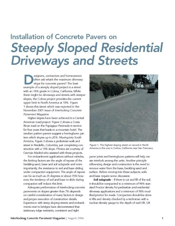
paver joints and herringbone patterns will help create interlock among the units Another principle influencing design and construction is the need to remove water from the base bedding sand and Fig ID: 260544

paver joints and herringbone patterns

Share:

Link:

Embed:

Download Presentation from below link

Download Pdf The PPT/PDF document "Installation of Concrete Pavers on Steep..." is the property of its rightful owner. Permission is granted to download and print the materials on this web site for personal, non-commercial use only, and to display it on your personal computer provided you do not modify the materials and that you retain all copyright notices contained in the materials. By downloading content from our website, you accept the terms of this agreement.


Presentation Transcript

Installation of Concrete Pavers on Steeply Sloped Residential Driveways and Streets paver joints and herringbone patterns will help create interlock among the units. Another principle influencing design and construction is the need to remove water from the base, bedding sand and Figure 1. The highest sloping street on record in North America is this one in Colma, California near San Francisco. Interlocking Concrete Pavement Magazine | August 2006 3 bar along the top in street applications. Reinforcing bar should be continuous. Use minimum 4,000 psi (30 MPa) concrete. Prior to forming the header, place and compact about 4 in. (100 mm) of base to serve as a platform for the forming the bottom of the concrete header. A larger header beam may be required in more severe climates or when truck traffic is expected. Locate the forms such that there is ½ in. (13 mm) gap between the end of the curbs and the header beam. This provides space for the drainage mat to continue the full length of the header beam so water can drain to each side of the driveway or road. The gaps can be covered with geotextile to contain base and bedding sand while allowing water to drain. The header beam should be formed, poured and forms removed prior to placing aggregate base against it. Construction joints should be placed a minimum of every 5 ft (1.5 m). These are daylight joints to reduce cracking risks and not joints made by tooling the beam surface. Besides controlling cracking, the joints will allow water to drain after rain during construction. After the concrete beam has cured a few days and forms are removed, (if necessary excavate and) compact the soil and place the drainage mat against the upslope side of the beam. Since running dump trucks and compaction equipment will damage the curbs, the following sequence should be considered: pour the curbs on the sides of the pavement, compact the soil and base up to the header beam location. Pour the header beam, then compact the soil, place and compact base after removal of forms around the cured header. The soil and base along the header beam will require compaction with a hand tamper or small equipment since it is unlikely that equipment will be able to reach corners. This is where density should be tested. More importantly, the drainage mat cannot be damaged, soiled or be allowed to fill with base along the edges during compaction. Cover the upslope side and top of the drainage mat to prevent base material from entering. Remove the cover after the base is completely compacted, meets density and elevation requirements. Immediately cover the top with geotextile to prevent ingress of base or bedding sand. This is indicated in Figure 4 with a small strip over the top of the drainage mat and anchored by the pavers.The drainage mat will extend the end of the header and direct water to one or both sides. The area outside the header and curb joints can be filled with No. 57 crushed stone or equivalent to facilitate drainage of water out of the drainage mat and down slope.In a few cases, the interlocking concrete pavement may abut an existing concrete slab. This could be a driveway apron or an abutting street. Careful consideration should be given on whether to construct a header beam to help direct water away from the side of slab. Care should be taken to Figure 3. Redevelopment of popular neighborhood in Medellín, Columbia included a 14% slope for the sidewalk and adjacent street.