/
Metropolis v1.0 MANUAL Metropolis v1.0 MANUAL

Metropolis v1.0 MANUAL - PDF document

briana-ranney
briana-ranney . @briana-ranney
Follow
381 views
Uploaded On 2017-02-20

Metropolis v1.0 MANUAL - PPT Presentation

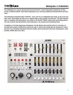
1 The Metropolis is a unique and powerful Eurorack format musical sequencer inspired by the Ryk M185 a Roland System 100m format sequencer but with many additional enhancements and func tions ID: 517817

1 The Metropolis unique

Share:

Link:

Embed:

Download Presentation from below link

Download Pdf The PPT/PDF document "Metropolis v1.0 MANUAL" is the property of its rightful owner. Permission is granted to download and print the materials on this web site for personal, non-commercial use only, and to display it on your personal computer provided you do not modify the materials and that you retain all copyright notices contained in the materials. By downloading content from our website, you accept the terms of this agreement.


Presentation Transcript

1 Metropolis v1.0 MANUAL The Metropolis is a unique and powerful Eurorack format musical sequencer inspired by the Ryk M-185 (a Roland System 100m format sequencer.) but with many additional enhancements and func - tions. The Metropolis comprises eight “STAGES”, each with its own assignable gate mode, pulse count and pitch value. Each stage can also have a special slide or skip function activated too. The slide function - ality is a constant time portamento very similar to the Roland TB303 (unlike most synths/sequencers that use constant rate portamento) which produces a very musical and interesting result. In addition to the base sequencer settings set with the sliders and switches there is a full menu of powerful ways including sequencer direction modes, pitch quantization and scale manipulators, clock 2 1 - AUX A input jack Patch a -5V to +5V source here for modulating the sequencer parameter assigned to AUX A . 2 - GATE output jack The sequencer gate signal (0V for off, 5V for on) is produced here. Typically you would patch this to the gate input of an ADSR or AHD envelope generator. 3 - PITCH output jack The pitch control voltage (CV) is produced here. This would usually be patched to the 1V/Oct or PITCH/FM inputs on a VCO. This signal is in the range of 0-5V and scaled to 1V/Oct. 4 - SYNC output jack A pulse is produced here at either the last clock pulse in a sequence or the �rst depending on the CONFIG menu setting for SYNC. The yellow led indicates the output state. 5. AUX B input jack Patch a -5V to +5V modulation signal source here for modulating the sequencer parameter assigned to AUX B. FRONT PANEL ELEMENTS 3 6. RESET input jack Patch a logic level signal (0-5V) here to reset the sequencer on either the next clock pulse or instantly depending on the CONFIG menu RESET option. 7. CLK input jack Patch an external clock source signal here (ideally 0-5V logic level or from a pulse LFO). This input only works when external clock mode is active (selected in the INT/EXT menu) 8. CLK output jack When the Metropolis is in internal clock mode (INT CLK) the BPM based clock is generated here. In external clock mode (EXT CLK) the external clock is divided and produced at this output. This clock frequency is divided by a value set with the DIV menu and is in a range of 1 (no division at all) to 32 (32 clock pulse internally must occur before one clock pulse externally is generated). In the CONFIG menu DIV TYPE submenu there is an option to change this output to generate a pulse at the beginning of each new stage instead of acting as a clock output. 9. DISPLAY All menu values and some real time sequencer data are displayed here. 10. BUTTON menu They are color coded as follows: RED - transport controls GREY - timing WHITE - sequence generation 11. GATE TIME manual control This knob allows you to manually set the gate time from the shortest possible gate length (full count - er clockwise CCW) to the longest (full clockwise CW). If one of the AUX inputs has been assigned to GATE LENGTH then the value set by this knob will be summed with the external modulation source. 12. EXIT BUTTON This button allows you to immediately exit any menu you have entered and return to the default dis - play mode. 13. DATA encoder A rotary encoder for setting values under the different menus and submenus. For the DIV, SAVE, LOAD and CONFIG menus one must click the encoder in order to complete the selection process. This is indicated by a �ashing display. In all other menus clicking the encoder will return the user to the default display mode. 14. SLIDE TIME manual control This knob allows you to set the pitch slide time for any sequence stage that has a slide button active. The time control ranges from 0 seconds (no slide) when fully CCW to approximately one second when full CW. Most sequencers and synthesizers use a constant rate style portamento but this slide functions as a constant time slide control much like the classic Roland TB-303. FRONT PANEL ELEMENTS (continued...) 4 15. SLIDE/ SKIP buttons Each of these buttons has dual functionality: Single click will activate a pitch slide for the given stage. A solid green indicates slide is active. Double click will set that stage to be skipped by the sequence. A �ashing green led indicates skip. 16. GATE MODE switches Each sequencer stage has four possible modes of operation with respect to the gate signal generated: HOLD - The gate output is held high for the number of clock pulses set by the pulse count switch for that stage. REPEAT - The gate output is repeatedly pulsed high based on the current STEP/DIV setting and the PULSE COUNT value for that stage. SINGLE - The gate output is high for one clock pulse and then stays low for a time deter - mined by the PULSE COUNT - 1. e.g. if PULSE COUNT for that stage is ‘3’ then the gate output is high for one clock pulse and then low for two. REST - the gate is held low for the number of clock pulses set by the PULSE COUNT switch for that stage. 17. PULSE COUNT switches Each of these switches sets a pulse count value for the associated stage in a range of 1 to 8 pulses. 18. PITCH sliders Each of these sliders sets the pitch for the associated stage. The led indicates the current gate state for that stage when the sequence is running. When in default display mode, the display will show the current quantized note value for each stage. If you move a slider, the sliders new pre-quantized value will be displayed along with slider number. FRONT PANEL ELEMENTS (continued...) 5 TRANSPORT FUNCTIONS RUN Toggles the start/stop of the sequence RESET Resets the sequence. �The behavior depends on the CONFIG- RESET mode. If RST n then reset occurs on the next clock pulse IF RST F then reset occurs if the CLK input is high at the same time as RST jack is high. PREV Stays on the current stage on the next clock pulse NEXT Skip the sequence ahead by one stage on the next clock pulse TIMING FUNCTIONS BPM When INT CLK mode is active you can set the BPM clock within the range of 20bpm to 320bpm. A single press of the button displays the current BPM. Any additional presses allow you to TAP TEM - PO the bpm value. You can adjust the new value with the encoder. When EXT CLK mode is active the BPM menu displays the detected external clock BPM. You will notice a dot �ashing after the second digit of the display to indicate an incoming clock that has not been LOCKED. What this means is that the incoming clock is being dynamically re-calcu - it is dramatically different from the previous BPM you will notice it takes a few seconds to properly average to the correct stable time. This has no effect on the down beat of each gate (which instantly matches external clock) but it may affect the gate length since this is based on an internal PPQ clock that runs at a much higher rate (96 PPQ) and is based on the detected value. Once the clock measurements are stable it is recommended to press the BPM button a second time. This will lock the internal BPM to the most recently calculated value. You will see the small dot stay in an on position to indicate locked BPM. If you press the BPM button a second time it will unlock the BPM You will notice that if you stop your external clock source (e.g. press stop on your DAW) and re-start then the clock will have to once again start measuring the incoming clock pulses if you are in BPM locked mode. Also once BPM is locked (locked from external measurement) you are still able to man - ually adjust the value with the encoder. SWING numbered clock pulse will be delayed by a percentage of the current clock interval. The swing ranges so that even steps will have longer gates than odd number steps. MENU FUNCTIONS 6 INT/EXT This allows you to select INT CLK mode or EXT CLK mode. The display �ashes to indicate that you choice is not active until you click the encoder. DIV Here you can set the divide clock output. The range of allowable values is determined by what divider mode you are in (as set in the CONFIG menu) IF CLK DIV mode = ALL: divider range 1 to 32 (where 1 represents no division) IF CLK DIV mode = EVE: divider range [1,2,4,6,....32] (even numbers only) IF CLK DIV mode = ODD: divider range [1,3,5,...31] (odd numbers only) IF CLK DIV mode = STA: no divider value can be set. Instead a clock pulse is generated at beginning of each new sequencer stage. SYSTEM CONFIGURATION FUNCTIONS AUX A Use the encoder to select one of six possible destinations for the AUX A input. Note that the selection is mutually exclusive to AUX B so whatever AUX B is assigned to will not be an available choice. P.PRE - shift the sequence +/-12 semitones before it is quantized. i.e. TRANSPOSE P.OCT - shift the sequence +/-4 octaves. i.e. TRANSPOSE P.POST - shift the sequence +/-12 semitones after it is quantized. i.e. KEY SHIFT ROOT - shift the root note of the current scale +/-12 semitones i.e. ROOT SHIFT G. LEN - change the gate length. This value is summed with the dedicated knob value STAGE - change the number of sequence stages or pulses (if in a �xed mode) by +/-16 STEPD - change the STEP/DIV value by +/-4 AUX B See AUX A. SAVE Allows you to save the current state of all the menu and submenu settings to a single location. This also includes all the slide and skip state buttons. This memory location is loaded by default each time Metropolis is power cycled. A �ashing S-YES or S - NO is selectable by the encoder. Choose S-YES and then click the encoder to save to EEPROM. Choose S - NO or any other button to exit this menu without saving. LOAD Allows you to load from EEPROM the last saved state of the system. A �ashing L-YES or L - NO is selectable by the encoder. Choose L-YES and then click the encoder to load from EEPROM. Choose L - NO or any other button to exit this menu without loading. MENU FUNCTIONS (continued...) 7 CONFIG The CONFIG menu comprises �ve �ashing submenu choices. To select a submenu item, select it with the encoder and then click to enter that submenu and set the values. 1. OCTAVES e.g. OCT_3 Sets the maximum number of octave range for the pitch sliders. Range of choices: 1 to 3 octaves 2. CLOCK DIVIDER MODE e.g. D_ALL Sets the clock divider mode used by the DIV menu Range of choices: D_ALL - ALL values from 1 to 32 D-ODD - Odd numbers only from 1 to 31 D-EVE - Even numbers only from 1 to 32 D-STA - STAGE SYNC mode 3. SYNC MODE e.g. SYNCL Sets the behavior of the SYNC output jack. Range of choices: SYNC L - the Sync pulse �res on the last clock pulse of the last stage of the sequence. 4. RESET MODE e.g. RST F Sets the reset jack behavior when in EXT CLK mode Range of choices: RST F - Sequence resets immediately when reset signal is high at the same time as clock RST N - Sequence will reset on the next clock pulse. This mode is useful if your DAW sends a reset signal when you stop the your DAW clock and you want the sequence to start at 1 when you restart. NOTE: If you are using the SYNC pulse to trigger another CV sequencer that is then feeding the CV values back to the Metropolis AUX inputs then it is recommended to use SYNCL mode. This causes the slave sequencer to generate new CV values earlier so that the AUX ADC inputs read them in time before the sequence advances. 5. FIRMWARE VERSION e.g. VER1.0 replacing the socketed chip on the back of the module or with the .hex code and an Atmel AVISPmkII programmer. MENU FUNCTIONS (continued...) 8 SEQUENCE GENERATION FUNCTIONS MODE There are 10 possible direction modes for the sequencer. These determine how the sequencer ad - vances between stages. FRD - FORWARD MODE The sequencer advances to each new stage in the forward direction starting at stage 1. The last stage is set in the STAGES menu. REV - REVERSE MODE The sequencer advances to each new stage in the reverse direction starting at the stage of the se - quence which is set in the STAGES menu. PNG - PING-PONG MODE stage (set in the STAGES menu) and then switches direction to advance in reverse until it reaches stage 1 again. RND - RANDOM MODE The sequencer advances to each new stage in a random order. The STAGES menu sets the total stages of the sequence can be randomly chosen. BRN - BROWNIAN MODE This is a pseudo random mode also sometimes referred to as “Drunken walk”. Starting at stage 1 There is a %50 chance of moving forward, %25 chance of staying on the same stage and a %25 chance of going backwards by one stage. The net result is that the sequence generally trends in the forward direction. The STAGES menu sets the total number of stages included in the pseudo random - ization. FRD-F - FIXED FORWARD MODE Same as FRD mode except that the total length of the sequence is determined by the total pulse count set in the STAGES menu. REV-F - FIXED REVERSE MODE Same as REV mode except that the total length of the sequence is determined by the total pulse count set in the STAGES menu. PNG-F - FIXED PING-PONG MODE Same as PNG mode except that the total length of the sequence is determined by the total pulse count set in the STAGES menu. RND-F - FIXED RANDOM MODE Same as RND mode except that the total length of the sequence is determined by the total pulse count set in the STAGES menu. MENU FUNCTIONS (continued...) 9 BRN-F - FIXED BROWNIAN MODE Same as BRN mode except that the total length of the sequence is determined by the total pulse count set in the STAGES menu. STAGES Sets the length of the sequence in terms of number of STAGES or PULSES depending on the direc - tion MODE that is currently active. STEP/DIV The step/div value determines how many clock pulses form a single gate if the gate mode for the stage is REPEAT. The range of values is 1 to 4 pulses. If STEP/DIV = 1 then the gate output goes high on every clock pulse If STEP/DIV = 2 then the gate output goes high on every two clock pulses If STEP/DIV = 3 then the gate output goes high on every three clock pulses If STEP/DIV = 4 then the gate output goes high on every four clock pulses E.g. If the PULSE COUNT for a stage was ‘5’ and the STEP/DIV was ‘2’ then the result would be would be a single clock pulse (1/16th). SCALE This allows you to select one of several standard scales used to quantize the values of the PITCH sliders. See the APPENDIX - SCALES for a full list of the available scales and their abbreviations. ROOT Here you can set the root note of the currently active scale. If active scale is CHROMATIC then you changing the ROOT will have no perceivable effect. MENU FUNCTIONS (continued...) 10 INPUTS AUX A, AUX B: -5V to +5V RESET, CLK: 0 to +5V (logic levels) OUTPUTS GATE, CLOCK, SYNC: 0 to 5V (logic levels) PITCH: 0 to 5V (1V/Oct scaling) MAX CURRENT DRAW 195mA @ +12V, 8mA @ -12V MODULE DIMENSIONS Width: 34HP Depth: 45mm This modular device is intended to be used in the Eurorack standard modular system and its associ - http://www.doepfer.de/a100_man/a100t_e.htm FIRMWARE UPGRADES TECHNICAL SPECIFICATIONS Firmware can easily be upgraded by replacing the socketed IC on the back of the Metropolis with a new IC obtained from Intellijel Designs Inc. or an authorized retailer. Carefully pry out the old IC. Then into the socket. 11 CREDITS WARRANTY Some features of the Metropolis were inspired by the work of RYK and his Roland System 100 format M-185 Sequencer. Design Consulting and Beta testing: Haven Siguenza Manual written by: Danjel van Tijn www.intellijel.com Intellijel Designs Inc. warrants this hardware product against defects in materials and workman - ship when used normally in accordance with Intellijel’s published guidelines for a period of TWO (2) YEARS from the date of original retail purchase by the end-user purchaser (“Warranty Period”). This warranty does not cover any damage or malfunction caused by incorrect use – such as, but not limited to, power cables connected backwards/incorrectly, connection of excessive voltage levels, or exposure to extreme temperature and/or moisture levels. The warranty covers replacement or repair, as decided by Intellijel Designs Inc.. Please contact our customer service (support@intellijel.com) for a return authorization before sending the module. The freight cost of sending a module back for servicing is the responsibility of the customer. Intellijel implies and accepts no responsibility for harm to person or apparatus caused through opera - tion of this product. © Intellijel Designs Inc. 2013 12 SCALE DISPLAY INTERVAL SET Chromatic 0, 1, 2, 3, 4, 5, 6, 7, 8, 9, 10, 11 Major 0,2,4,5,7,9,11 Minor 0,2,3,5,7,8,10 Dorian 0,2,3,5,7,9,10 Mixolydian 0,2,4,5,7,9,10 Lydian 0,2,4,6,7,9,11 Phrygian 0,1,3,5,7,8,10 Locrian 0,1,3,4,7,8,10 Diminished 0,1,3,4,6,7,9,10 Whole-half 0,2,3,5,6,8,9,11 Whole Tone 0,2,4,6,8,10 Minor Blues 0,3,5,6,7,10 Minor Penta 0,3,5,7,10 Major Penta 0,2,4,7,9 Harmonic Minor 0,2,3,5,7,8,11 Meldoic Minor 0,2,3,5,7,9,11 Super Locrian 0,1,3,4,6,8,10 Arabic / Bhairav 0,1,4,5,7,8,11 Hungarian Minor 0,2,3,6,7,8,11 Minor Gypsy 0,1,4,5,7,8,10 Hirojoshi 0,2,3,7,8 In-Sen 0,1,5,7,10 APPENDIX A - SCALES 13 SCALE DISPLAY INTERVAL SET Japanese / Iwato 0,1,5,6,10 Kumoi 0,2,3,7,9 Pelog 0,1,3,4,7,8 Spanish 0,1,3,4,5,6,8,10 Tritone (2 semitone ver - sion) 0, 1, 4, 6, 7, 10 Prometheus 0, 2, 4, 6, 9, 10 Augmented 0, 3, 4, 7, 8, 11 Enigmatic 0, 1, 4, 6, 8, 10, 11 APPENDIX A - SCALES (continued...) 14 Startup display Default active display showing currently active pitch and a sequence animation. When a pitch slider is moved the slider number and new pitch are displayed. e.g. slider 4, pitch = D3 BPM BPM with external lock on Clock External mode Clock Internal mode Clock Divider with value 2 Clock Divider with Stages Sync Out Save - NO Save - YES Load - NO Load - YES Forward mode Reverse mode Ping-pong mode Random mode Brownian mode Forward Fixed mode Reverse Fixed mode Ping-pong Fixed mode Random Fixed mode Brownian Fixed mode APPENDIX B - DISPLAY ABBREVIATIONS & EXAMPLES 15 AUX DESTINATION - Gate Length AUX DESTINATION - Pitch Pre (Transpose) AUX DESTINATION - Octave Shift AUX DESTINATION - Pitch Post (Key shift) AUX DESTINATION - Root AUX DESTINATION - Stages AUX DESTINATION - Step Divisor Stages with value of 8 Pulses with value of 8 Step/Div with value of 3 Root with value of C# CONFIG - Octave range 3 CONFIG - clk divider mode ALL CONFIG - clk divider mode EVEN CONFIG - clk divider mode ODD CONFIG - clk divider mode STAGES CONFIG - SYNC mode last beat CONFIG - RESET mode �rst beat CONFIG - RESET mode next beat Firmware Version with value 1.0 APPENDIX B - DISPLAY ABBREVIATIONS & EXAMPLES (continued...) 16 APPENDIX C - PATCH EXAMPLES EXAMPLE 1: BASIC PATCH In the EXAMPLE 1 pitch and amplitude of a VCO. The PITCH output from the Metropolis is connected to the 1V/Oct in - put of the VCO. One of the VCO’s output waveforms (e.g. a saw wave) is then connected to the audio input of a VCA. The GATE output is connected to the gate input of an ADSR. The envelope output of the ADSR is then connected to the CV input of the VCA in order to control the amplitude. It is important to adjust the ADSR levels to get the desired response when the Metropolis gate length is set to it’s minimum value. i.e. you want to make sure that it results in a short click with a tiny bit of decay. 17 APPENDIX C - PATCH EXAMPLES (continued...) EXAMPLE 2: MODULATED SEQUENCE PATCH The patch in EXAMPLE 2 demonstrates a way to generate a sequence that is being modulated. Metropolis#1 can be in either EXT or INT CLK mode and is connected to a VCO, VCA and ENVE - LOPE generator similarly to EXAMPLE 1. The SYNC output jack is used to clock the CLK input of the second Metropolis (or any other CV sequencer). The SYNC pulse has been con�gured to �re on the last clock pulse of METROPOLIS #1 �by choosing the CONFIG-SYNCL option. METROPOLIS #2 should be in EXT CLK mode but it can be in any direction MODE, STAGE length etc. For this example it is suggested to try setting stages to 4 with a pulse count of 1 on each stage and MODE to FRD. This means that every time METROPO - LIS #1 completes one cycle of its sequence METROPOLIS #2 will advance by one stage and cycle through its 4 different pitches. The PITCH output of METROPOLIS #2 is connected to one of the AUX inputs of Metropolis #1. If this AUX input is set to P. PITCH. P. OCT, P.POST or ROOT then you will get an interesting, repeatable musical change on every sequence cycle. If the sequence on Me - tropolis #1 was 1-BAR long then the repeating resultant musical sequence would be a 4-BAR phrase.