PDF-MOUNTING INFORMATION
GridDrywall
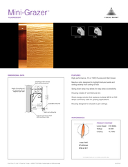
Acoustical tile may rest on flange of luminaireMount drywall under luminaire and support to ceiling structureNOTE Add drywall thickness to overall height
Download Presentation
"MOUNTING INFORMATION" is the property of its rightful owner. Permission is granted to download and print materials on this website for personal, non-commercial use only, provided you retain all copyright notices. By downloading content from our website, you accept the terms of this agreement.
Presentation Transcript
Transcript not available.