/
SW versjon 404X SW versjon 404X

SW versjon 404X - PDF document

byrne
byrne . @byrne
Follow
342 views
Uploaded On 2021-08-10

SW versjon 404X - PPT Presentation

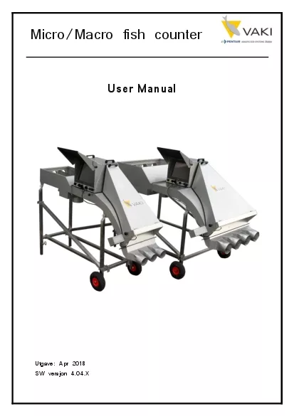
UtgaveApr 2018User ManualMicroMacro fish counterManual for VAKI MicroMacroPage 1Contents1Preface The MicroMacro Fish Counters32Warranty43Components64Counter head85Set Up116Pumping1261 Vacuum Pumps1 ID: 861261

macro counter counting fish counter macro fish counting micro vaki channel manual figure page head water session visibility report

Share:

Link:

Embed:

Download Presentation from below link

Download Pdf The PPT/PDF document "SW versjon 404X" is the property of its rightful owner. Permission is granted to download and print the materials on this web site for personal, non-commercial use only, and to display it on your personal computer provided you do not modify the materials and that you retain all copyright notices contained in the materials. By downloading content from our website, you accept the terms of this agreement.


Presentation Transcript

1 Utgave : Apr 2018 SW versjon 4.04.X
Utgave : Apr 2018 SW versjon 4.04.X User Manual Micro/Macro fish counter Manual for VAKI Micro/Macro Page 1 Contents 1 Preface – The Micro/Macro Fish Counters ................................ ................................ ..................... 3 2 Warranty ................................ ................................ ................................ ................................ ......... 4 3 Components ................................ ................................ ................................ ................................ .... 6 4 Counter head ................................ ................................ ................................ ................................ .. 8 5 Set Up ................................ ................................ ................................ ................

2 ................ ............ 11 6
................ ............ 11 6 Pumping ................................ ................................ ................................ ................................ ........ 12 6.1 Vacuum Pumps ................................ ................................ ................................ .......... 12 6.2 Netting ................................ ................................ ................................ ....................... 12 7 Oppstart ................................ ................................ ................................ ................................ ........ 13 7.1 Turn on counter ................................ ................................ ................................ ......... 13 8 Main screen ................................ ................................ ................................ ....

3 ............................ ... 14
............................ ... 14 9 Calibrating and Visibility ................................ ................................ ................................ ............... 19 9.1 Visibility ................................ ................................ ................................ ...................... 19 Visibility Examples ................................ ................................ ................................ ......................... 21 9.2 Calibrating the counter ................................ ................................ .............................. 23 10 Set fish size ................................ ................................ ................................ ................................ 24 11 Test with water only ................................ ................................ .....................

4 ........... .................. 25 12
........... .................. 25 12 Start Counting Session ................................ ................................ ................................ ............... 26 12.1 Store and Continue Counting ................................ ................................ .................... 27 12.2 Pausing the sessio n ................................ ................................ ................................ .... 27 12.3 Reset one or more channels to zero ................................ ................................ ......... 28 13 Ending the session ................................ ................................ ................................ ..................... 28 14 The report ................................ ................................ ................................ ................................ .. 29 15 Re

5 viewing the counting session .........
viewing the counting session ................................ ................................ ................................ 33 Manual for VAKI Micro/Macro Page 2 16 Settings ................................ ................................ ................................ ................................ ...... 35 17 Switch between single and multi channel mode ................................ ................................ ...... 37 18 Storage of the counter ................................ ................................ ................................ .............. 37 Technical specification ................................ ................................ ................................ ......................... 38 Standard Counters ................................ ................................ ................................

6 ................................ 40
................................ 40 Manual for VAKI Micro/Macro Page 3 1 Preface – The Micro/Macro Fish Counters VAKI Aquaculture Systems thank you for choosing the MICRO and MACRO range of fry and smolt counters. These counters are used in many aquaculture enterprises where an accurate knowledge of fish numbers is important. Applications include counting fish when grading, accurate stock control and when transferring fish between tanks and delivering fish by heli copter, well boat and truck. The MICRO and MACRO counters have been developed in collaboration with a number of leading fish farming companies and used worldwide for counting a wide variety of species including Atlantic and Pacific salmon, trout, char, se a bass, sea bream, cod, tilapia, cobia, yellowtail, flatfish and most other farmed fin fish species. Vaki continue to develop the fe

7 atures and functions of the counters for
atures and functions of the counters for use with more specialised species including prawn, shrimp, eel and ornamental fis h. The counters are based on a digital scanning camera and computer vision. The outlines of objects that pass beneath the camera are recorded and custom designed software is used to analyse the images and count the individual fish. The fish enter the coun ter and the water from the fish pump or spray bar then carry the fish over the curved counting channel. The fish then pass over a light source and a mirror above the light reflects the images of each fish back to the digital camera where the outlines are r ecorded and counted. The MICRO is ideal when counting small fish from 0.2 g and has a 500mm wide counting channel, the MACRO channel is 1000mm wide and ideal for counting both fry and larger fish such as smolts. Both counters can be supplied with multi co

8 unting channels, which can be used to co
unting channels, which can be used to count separate batches of fish simultaneously, for example when grading. This manual is a guide to the use of the MICRO and MACRO counters. Manual for VAKI Micro/Macro Page 4 2 Warranty VAKI Aquaculture Systems Ltd. offers warranty for and manufacturing defects that appear within one (1) year from the date of delivery from VAKI Iceland, on condition that the equipment has been assembled, used and maintained in accordance with the instruct ions for assembly and use. Changes to the start date of this warranty, such as delayed delivery to the user, must be reported to VAKI upon receipt of the equipment and agreed in writing. VAKI undertakes to repair all defects that are due to faults in the design, materials used, or manufacture of the equipment. These defects will be rectified by repairing the equipment, or replacing componen

9 ts. The customer may be required to retu
ts. The customer may be required to return the complete unit or parts thereof to the factory in Iceland for repair. V AKI accepts corresponding warranty for original parts fitted by VAKI as replacements, for a period of one (1) year from the date supplied. VAKI will not be liable for:  Incorrect assembly and use, or inadequate maintenance  Defects which result from the fitting of materials, components or devices not supplied by VAKI, and which are purchased and fitted by the user.  Defects due to changes made to the equipment by the user, without the written consent of VAKI.  Faulty or inadequate repairs carried out by the user.  Normal wear and tear of the equipment.  Faulty connection of electrical equipment  Faults caused by excessive voltage.  Damage or stoppage due to immersion of the computer or camera in water. 

10 Damage to electrical supply cables. ï
Damage to electrical supply cables.  Any economic lo ss that my arise from production stoppage. Manual for VAKI Micro/Macro Page 5 If faults or defects appear in the equipment, the user must report this in writing to VAKI or its appointed representative as soon as possible, and without unjustifiable delay. The report must be sent within two (2) weeks from the expiry of the deadline, which is one (1) year from the date of supply by VAKI Iceland. If the purchaser does not inform VAKI or its representative within the time limits stated above, the purchaser shall forfeit the rights of the warran ty. Manual for VAKI Micro/Macro Page 6 3 Components After delivery, the main parts of the counter need to be bolted together. These are the Counting head, Counter body, legs, inlet, and outlet. The legs are assembled and fitted with the wheels at the

11 front and the inlet tub and outlet bolt
front and the inlet tub and outlet bolted to the counter body as shown. Instructional video is availible at www.vaki.is. To ensure the camera i nside is correctly positioned it is important that the counting head is securely fitted onto the main chassis and firmly seated on the four corner pads. The Micro / Macr o can be supplied as a single channel counter or with multiple channels. The four - channel Macro counter is shown here. The main steps in the assembly are always the same but there may be different inlets and outlets according to the counter specifation. Figure 2 - Counter Components 1. Multi - Channel inlets 2. Counter Head 3. Counter Body 4. Channel 5. Multi channel outlet 6. Legs 7. Lamp housing 8. Dewatering outlet 9. Up - well inlet Figure 1 - Counter Assembly Manual for VAKI Micro/Macro Page 7

12 Other equipment supplied :  Count
Other equipment supplied :  Counter Manual  Power cable  Temporary license for size estimation (3 month)  Multi channel outlet (For multi channel counters)  Single channel outlet (For single channel counters) Optional extras :  Size estimation  Back - up power supply & surge protection  USB mouse and keyboard  Single channel outlet  Nettverkskabel.  Single channel outlet (Not included with multi channel counters)  Kit for intern oppvarming. Manual for VAKI Micro/Macro Page 8 4 Counter head The counter can be supplied with a counting head where the camera, power supply, heating element and PC with touch screen are integrated in the head or with the so - called split head solution where the PC comes as a separate device which can either be mounted on a bracket on the head,

13 or away from the counter itself. At /
or away from the counter itself. At / below the screen there are connection ports and inputs for connection of power, lamp, alarm and any accessories such as keyboard / mouse / printer. The counting head is constantly evolving, so there are slightly different versions on the market. The figures below show two versions where PC is integrated into the head. Figure 3 - Old head design Figure 4 - New head design 1. 110/220VAC power connector 2. On/Off button 3. Ethernet port 4. USB port 5. USB port 6. Serial port 7. Control port for overload/batch alarm 8. Lamp /heater connector Manual for VAKI Micro/Macro Page 9 The split head solution may look like the pictures below. Figure 5 - 4 Channel Macro w/ Split Head The PC can be mounted on both sides of the counter, or away from the counter. If the

14 PC is mounted far away from the counter
PC is mounted far away from the counter, it will need a seperate power supply, and an ethernet cable to connect it to the counter head. Figure 6 - Split head side view Split head solution seen from the side. 1. Bracket where the PC is mounted on. 2. Lamp/heater connector Manual for VAKI Micro/Macro Page 10 Figure 7 - Split head rear On back of the head there is:  110/220VAC Power in  12V Computer power  Ethernet connector  On/off button Figure 8 - Split head front On the other side of the head : 1. Ventilation 2. Glass window which the camera looks through Manual for VAKI Micro/Macro Page 11 5 Set Up When setting up the MICRO or MACRO it is important to note the following:  The counter should be placed on a flat and stable surface.  Set the counter lev

15 el by adjusting the height of the legs t
el by adjusting the height of the legs to ensure both fish and water are evenly spread across the scanning area.  Ensure that the leg supports are properly secured.  L ocate the counter so that the touch screen is easily accessible and not exposed to water or direct sunlight. Note that in hot weather, high temperatures can affect the computer.  Before each count check that the mirror is completely clean and free from any stains, residue or water droplets.  Ensure that all pipes and hoses are securely fastened.  Connect the lamp cable to lamp connection on counting head.  Connect external alarm or batch splitter to the “Alarm” port  Connect the power cable to earthed power out let. The use of a UPS (un - interrupted power supply) device is recommend. The counter power requirement is 80 - 100W .  Ensure that water and fish have a

16 continuous free flow from the counter. B
continuous free flow from the counter. Backpressure in the pipes can overload the counter.  Take care not m ove or shake the counter while it is operating to protect against hard disk failure. Manual for VAKI Micro/Macro Page 12 6 Pumping When using a fish pump to transfer fish to the counter it is important to ensure an even flow of fish and water. Uneven delivery of fish to the counter can c ause inaccurate counting as the number of fish may exceed the capacity limits. It is also important to test the counter on the correct fish size settings pumping water only to ensure excess water does not create over - counting and adjust pump as required. Ref: section 7.2 “Test with water only” 6.1 Vacuum Pumps When using larger vacuum pumps it may be necessary to provide additional dewatering or a buffer tank. Short bursts of many fish can overlo

17 ad the counter and both excess water and
ad the counter and both excess water and white water can aff ect the performance of the counter particularly when counting smaller fish. 6.2 Netting When netting the fish into the counter it is similarly necessary to supply a sufficient amount of water for gentle handling of the fish and maintain an even flow of fis h over the curved counting channel. Manual for VAKI Micro/Macro Page 13 7 Opps t art The counter is now assembled and set up as instructed. 7.1 Turn on counter Wait for approximately 10 minutes for lamp to reach it’s full operation temperature. The counting program will normally start automatically. If it does not, then the counting program can be started by pressing the icon "oripassin - Shortcut". If the counter is used at low temperatures, it is important that it is switched on well in advance of the operation in order for the ligh

18 t to reach full operating temperature.
t to reach full operating temperature. Figure 9 - Computer start - up screen Manual for VAKI Micro/Macro Page 14 8 Main screen Figure 10 - Counter main window 1. Average flow changes between "Average flow", "Total count" or "Flow last X minutes" as it is pressed. The button is used to see either the flow through the respective channels for the last 1 - 10 minutes (the number of minutes can be adjusted with the Up / D own buttons corresponding to the size setting), or the normal display with the number per channel (Total count). 2. START SESSION starts a new count . 3. STOP SESSION stops the session and generates a report. 4. Pause lets you pause the session, for example if you need to clean the mirror during a counting session 5. Store stores the values on each channel, but does not clear the values. Stored values are

19 displayed in the counting report. 6.
displayed in the counting report. 6. Settings are pressed to open the settings menu. 7. Images is used to review the imag es from a previous counting session. 8. Report is used to review the report from a previous counting session. Manual for VAKI Micro/Macro Page 15 9. Calibrate is pressed to calibrate the counter before a counting session. 10. Press EXIT to close the counting software. Figure 11 – Counter main window 2 A. Fish size adjustment buttons to be counted in the different channels. Choose the weight closest to the expected average for the fish to be counted in the current channel. Selected weight is displayed directly above the buttons . B. Load indicator showing how much the counter load is . The bar will be green from 0 - 100%, yellow from 100 - 130% and red at load over 130%. The risk of miscalculation i

20 ncreases with increasing load over 100%
ncreases with increasing load over 100%. C. Channels. The names can be changed by pressing the respective channel names - the on - screen keyboard will then appear. D. Estimated average weight is shown in these fields provided the size measurement is enabled. (The progress indicator that becomes visible at the beginning of the count is a symbol that the counter must measure a number of fish before it has a basis for estimating the average weight. The number of estimated average weight appears when a sufficient number is measured.) Manual for VAKI Micro/Macro Page 16 E. Counting or Not Counting indicates whether the counter is ready for cou nting. If this area is red, "Not counting" shows and there is an error message regarding visibility and / or calibration, see chapter for Calibration and Visibility. F. Number of fish through the channel . If you do

21 uble - click in this field, you will be
uble - click in this field, you will be able to store the value and reset the value in the field . You will be prompted with a confirmation window before the field is stored and reset. Resetting does not affect the total number. G. Percentage of total number of fish through current channel. H. Total fish in a ll channels. You can double - click in this field to switch between the total number and sub total - where sub total is the current sum for all channels, ie it deviates from the total number if one or more of the channels has been reset. Manual for VAKI Micro/Macro Page 17 Throughput : Grap hs will show fish per minute through the counter. The red line shows maximum capacity , the others show the number actually measured in the corresponding channel. Figure 12 - Throughput Video : Real - time display of the camera's video imag

22 e. This can be used to see how fish pass
e. This can be used to see how fish pass through the counter and to see impurities on glass / mirrors. Figure 13 - Video Spread : A graphical representation of where in the counting field the fish pass. Figure 14 - Spread Visibility : Displays the light intensity recorded by the camera. Figure 15 - Visibility Manual for VAKI Micro/Macro Page 18 Information : Technical information about the counter. Figure 16 - Information In the above information field, it is important to note the following information:  Light strength – shows the brightness measured by the camera. The value should typically be 1000 - 1400. If the value comes below 700, it must be checked if it can be impro ved by cleaning the mirrors and glass. Another option may be to replace the bulb , or a VAKI service technician may need to be c

23 alled in to adjust the camera. Low lig
alled in to adjust the camera. Low light strength will also be displayed if the bulb has not reached it maximum operating temperature. After washing or other measures, the counter must be calibrated to obtain new brightness value.  Scan rate – shows how many scans the camera performs each second. This value should be ~ 1116 Example of load indicator : Figure 17 - Load indicator Manual for VAKI Micro/Macro Page 19 9 Calibrating and Visibility When the counter starts, the following tests are performed:  Scan area of the camera.  All bulkheads are detected.  The brightness measured by the camera. If visibility is not satisfactory, then an error message will appear saying "The visibility is insufficient, the counter will not count. Check visibility scope. ”The Visibility graph can then help to fin d a soluti

24 on to what is wrong. 9.1 Visibility
on to what is wrong. 9.1 Visibility Press the Visibility button to display the visibility graph. The black vertical lines represent the outer edges of the counting field, for a 4 - channel Macro they will also represent the three seperators (bulkhe ads) between the channels - see the figure below. Figure 18 - Visibility of a 4 channel Macro The Visibility function is used to check that the camera is properly tuned and that the gain of the light is correct. The function can also be used to detect any impurities or foreign elements that block the light, or an abnormal tilt of the counter head. In the figure above, we see a normal curve for the brightness (fluorescent lights shine most in the middle). The X - axis represents the width of the scanning area in pixels (1 pixel ≈ 0.55 mm). The Manual for VAKI Micro/Macro Page 20 graph of Macro should have

25 a span of about 1800 (1000 mm), the ex
a span of about 1800 (1000 mm), the exact value depends on the type of camera and lens used. The Y - axis represents the brightness on a scale from 0 to 255. The counter must be calibrated if the brightness is below 180 or above 250. Manual for VAKI Micro/Macro Page 21 Visibility Examples Figure 19 - Visibility Example 1 The diagram on the left shows how the graph can look if there are any impurities on the glass / mirror, and the brightness is somewhat low. It is reasonable to assume that there are impurities on glass over light, possibly on mi rrors, at the x - axis value about 550, 1100 and 1700, represented by thin falls in the brightness graph. In this case, it would be good to clean the glass and mirrors, and calibrate the counter. Figure 20 - Visibility Example 2 This diagram also shows dirt or other impurities on the glass or th

26 e mirror. The waves in the curve also i
e mirror. The waves in the curve also indicate that the bulb has not reached full operating temperature. Figure 21 - Visibility Example 3 Here, the light curve i s also changed due to impurities on glass and mirrors. In this case, it is possible that a calibration cannot be carried out, and thus washing must be carried out before counting. In this case, the camera may also be misaligned. Manual for VAKI Micro/Macro Page 22 Figure 22 - Visibility Example 4 It is possible to zoom in the visibility graph. By clicking and dragging to the right and down, you can zoom in on a portion of the graph. Figure 23 - Visibility Example 5 This figure shows the result of zooming in on one of the bulkheads. To get back to the entire graph, one can click - and - drag left and up anywhere on the chart. Figure 24 - Visibility Example 6

27 This is an example of how the graph
This is an example of how the graph may look if the light is not turned on or that the counting head is incorrectly mounted on the counting body. Manual for VAKI Micro/Macro Page 23 9.2 Calibrating the counter The counter should be calibrated without water before use . It is important that the light has been on for a minimum of five minutes, and that glass and mirrors are clean before the calibration is started. The calibration resets the camera to its metering. Press the Calibrate button on the main screen without wat er and / or fish passing through the counter. While the calibration is in progress, Not Counting will appear at the bottom left corner of the main screen, this will change to Counting if the calibration is OK. You may also want to check the Visibility curve after calibration to see if there may be other issues. Figure 25 - Counte

28 r Calibration Manual for VAKI Micro/
r Calibration Manual for VAKI Micro/Macro Page 24 10 Set fish size The size groups are : 0.1g, 0.3g, 1g, 3g, 10g, 30g, 100g, 3 00g , 1 kg og 3 kg. Using the size group buttons set the size group closest to the average size you intend to count. Each size setting covers a range of fish approximately 5 x smaller and 5 x larger than the size setting. Should sensitive settings for very small fry count small air bubbles, water disturbance, or suspended particles it is advisable to increase the initial size range. Manual for VAKI Micro/Macro Page 25 11 Test with water only Adjust the amount of water from the fish pump to suit the size of fish being counted. With smaller fish, reduce the amount of water as much as possible running through the counter to prevent miscounting. Use the dewatering valve to adjust the water level. The plastic flap i

29 s used to even the flow of water and fi
s used to even the flow of water and fish th rough the counter. The dewatering valve is adjusted using this screw Test run with water only through the counter and check that the counter does not show any counts due to water disturbance. It may be necessary to adjust the flow of water to prevent this, particularly with small fry. If the counter is “counting the water”, this may be due to:  The surface of the mirror is dirty or has water splashes.  Too much water is being pumped through the counter.  The water may be too dirty.  The counter is not lev el and/or the water is not evenly spread over the counting channel.  The size range setting is too sensitive. Manual for VAKI Micro/Macro Page 26 1 2 Start Counting Session To start counting press “ New counting session ” button on the main screen. The display w

30 ill show: Figure 26 - Starting
ill show: Figure 26 - Starting a new counting session The text entered in the fields will be included in the count report generated after counting. If necessary, press the button to the right of the text fields (shown at 1 in the figure above) to bring up the screen keyboard. If this keyboard is used, press CLOSE between each entry and press the keyboard button of the next field where you want to enter information. Press the OK button after entering the desired information. The information posted h ere will also be visible in the VAKI Cloud. Detailed accurate information then makes it easier to identify the sessions for later reference. IT IS IMPORTANT THAT ONLY LETTERS AND NUMBERS ARE USED WHEN A NAME IS GIVEN. DO NOT USE SIGNS SUCH AS ( / , . & - OR THE DATA FILE WILL NOT BE SAVED. The counter should now show 0 in all counting windows. Start pumping or netting the f

31 ish into the counter. Manual for
ish into the counter. Manual for VAKI Micro/Macro Page 27 12 . 1 Store and Continue Counting When the count is started, the buttons on the main screen will change to STOP SESSION, Pause and Store. Pause is pressed to make a stay in the count if, for example, the counter requires cleaning. Store is pressed to make note of the current count numbers in the report. Figure 27 - Main screen buttons after starting session Also note that one cannot select Settings , Calibrate or Exit while a count is in progress. If a Store is pressed, the following message appears on the screen. The counting result in that button will be stored in the report along with the time. Figure 28 - Storing numbers message 12 .2 Pausing the session If, for various reasons, a pause in the count and thus the data entry is appropriate, the Pause

32 button can be used. This can, for examp
button can be used. This can, for example, be relevant if glass and mirrors have to be washed in the middle of the count, or that there is a stay in the deliver y of fish. After pressing Pause , the button changes to Continue, and the field around the channels gets a red color to indicate that the count has stopped. Press Continue to continue counting. Figure 29 - Pause screen Manual for VAKI Micro/Macro Page 28 12.3 Reset one or more channels to zero It is possible to reset the number of fish that have passed through the channels. Double - click the number for the respective channel, then press OK in the window that appears. Alternatively, Cancel if you do not want to reset. Resetting the channels does n ot affect the total number. Figure 30 - Reset channel 1 3 Ending the session When you have finished counting, press the STOP

33 SESSION button. The following message
SESSION button. The following message then appears on the screen. Press OK to end the count or press Cancel to continue counting. Figure 32 - End session confirmation Furthermore, the following window will appear on the screen if you press OK, indicating that the system is exporting the data and creating a count session report. The count report includes, among other things, the total number of fish and numbers for each channel, any intermediate values, and information on the load during the ses sion . In addition, the image file is stored for any subsequent check of the result. It is now possible to review the session, either by taking a look at the report or the images. Double click here Figure 31 - Exporting message Manual for VAKI Micro/Macro Page 29 14 The report Press the Report button to open and view the reports. A li

34 st of all saved reports will then appea
st of all saved reports will then appear. The file name will contain the date and text entered in Session description in the window one gets up after pressing START SESSION (ie the first 15 characters of this text) . Also note that the report is saved as a PDF file in C: \ Reports. Figure 33 - Insert session information If the biomass measurement is activated, the report will also contain average weight, total biomass, standard deviation and a chart showing the size distribution. Company name and logo can be included in the report. This information is entered in Settin�gsFolders. Figure 34 - Entering company information Manual for VAKI Micro/Macro Page 30 Counting report example: Figure 35 - Counting report example Manual for VAKI Micro/Macro Page 31 Weight distribution graph example: (Optional ad

35 d - on) Figure 36 - Weight di
d - on) Figure 36 - Weight distribution graph Manual for VAKI Micro/Macro Page 32 Stored values is displayed at the end of the report if any values have been stored: Figure 37 - Stored values Manual for VAKI Micro/Macro Page 33 1 5 Reviewing the counting session Press Images on the main screen to view the recording of the count (image file). These files ha ve the same name that the report, date and description. Each image represents approximately one second of the recording. Figure 38 - The image file 1. The upper graph shows the load on the counter, ie fish through the counter per time unit. Click on the chart to switch between channels. 2. This pointer shows where in the recording the current image comes from. 3. This pointer can be used to navigate the recording. 4. Navigation butto

36 ns in the recording: ◄ ► - t
ns in the recording: ◄ ► - these buttons are used to move the screen back or forward one step .  ◄ ►  - these buttons are used to go to the beginning or end of the recording . 5. This field contains the name of the channel, the size setting and the number of fish shown in the image. Note that if ► is pressed , the number shown will added to the previous number Manual for VAKI Micro/Macro Page 34 displayed. If ◄ is pressed , the number displayed will reset to the current number of the current image. Partial fish images are counted on the next frame. 6. The START / END button is used to select an area o f the count to be controlled. For example, set the pointer (3) to the desired start time. Press the START button. The button then changes to END . Then move the point 3 to the desired end time and press the END

37 button. Then, the number of fish betwee
button. Then, the number of fish between sta rt and end time is re - counted. Manual for VAKI Micro/Macro Page 35 16 Settings On the main screen, press Settings to access the settings menu for the counter. In this window you can choose the language (English, Icelandic, Norwegian and Spanish). The weight constant is used to fine - tune the weight estimation for each fish species. The general rule is to increase/decrease the weight constant by 50% of the error. Example: the average weight result is 110gr, but 100gr was expected, so the result is be lieved to be 10% too high, so the weight constant should be increased by 5% (1,05x128) = 135 should the new weigth constant. To switch between multi channel and single channel counting, use the Multi channel counting checkbox. Counter type indicates whic h type of counter the head is mounted on

38 . The counter name can also be change
. The counter name can also be changed. Manual for VAKI Micro/Macro Page 36 Figur 2 Under Licence codes you enter the license for the counter depending on what type of body the head is going to be used with. To enable the biomass measurement, a pin code must be entered in the window that appears when you press the Pin kode button . Fig ur 3 Figur 1 Under Folders it is possible to enter the name of the operator/company, and the company logo, and these will then appear on the count report. Under Folder for Report and Record files it is possible to select the folder that the reports are stored in. The dropbox function has been discontinued, and has been replaced with an alternative in version 5.xx.xx Manual for VAKI Micro/Macro Page 37 17 Switch between single and multi channel mode Both Micro and Macro c

39 ounters are available as multi - channel
ounters are available as multi - channel counters that can be connected to a sorting machine. The counters can also be used in single - channel mode. To convert from multi - channel to single - channel, the channels must be removed. Fish can then be pumped into the up - well inlet under the counter, or alternatively heaped in. Channel dividers that cover two channels are also available. This is particularly relevant when it comes to sorting, and one group of fish, for example, accounts for 60 - 70% of the total. That way, this amount of fish can be distributed over a larger area of the counting field, which helps maintain capacity and accuracy. The multi - cha nnel outlet can also be replaced with a one - channel outlet. In the counting program, you can switch between single - channel or multi - channel counting under Settings and Settings. However, it is recommended to leave

40 the counter in multi - channel mode eve
the counter in multi - channel mode even if it is used with only one channel. This allows monitoring of fish passing through each channel sector to ensure that fish are spread throughout the counting field and that one can maintain capacity to a maximum. 18 Storage of the counter When storing the c ounter, it is important to pay attention to the following :  Use fresh water to remove any residual salt water from the counter after use.  Store the counter in a dry place where there is little temperature variation.  The counter head must be handled with car e. Do not lift the counter with the head attached.  Feel free to remove the PC or counter head and store it in a location where it is protected from moisture, shock and temperature variations.  Cover any open contacts on the PC and counting head. Manual for VAKI Micro/Macro Page 38

41 Technical specification Macro
Technical specification Macro Size: 2.5 x 1.2 x 1.6 - 2.4 m (L x W x H) Micro Size: 1.5 x 0.7 x 1.6 - 2.4 m (L x W x H) Material: Stainless steel (AISI 316L) Light source: Micro Counter Macro Counter 18W 60cm 18/12 - 950 36W 120cm 18/12 - 950 Osram colour ref 950 Power consumption: 110/220 V UPS requirement: 80 - 100W Size of inlet/outlet pipes: 4”on Micro / 6” on Macro Size of dewatering pipe: 4” on Micro / 6”on Macro Manual for VAKI Micro/Macro Page 39 Capacity: Fish size Micro Counter Macro Counter Fry/min 0,5 g 9500 14000 1 g 6500 10200 3 g 4300 7200 10 g 2800 4800 30 g 1600 3080 100g 800 1600 200g 600 1200 Accur

42 acy: 98% - 100% Fish sizes:
acy: 98% - 100% Fish sizes: Macro 0.2g – 400g Micro 0.2g – 200g Fish species: Sea bass, sea bream, salmon, trout, halibut, turbot, tilapia, cod,yellow tail, turbot and ornamentals. Manual for VAKI Micro/Macro Page 40 1300 mm 1600 mm Standard Counters Single Channel Macro Legs are adjustable for up to 500mm extra height. Sizes are approx. for a standard counter. 4 Channel Macro Quattro 2800 mm 1000 mm Manual for VAKI Micro/Macro Page 41 The Macro counter is split into 4 separate counting channels. The channel dividers in the inlet can be removed and the upwelling inlet used to convert to single channel for fast deliveries. Single Channel Micro The counting channel is 500mm wide x 70mm deep. The Micro can also supplied as a 3 channe

Related Contents


Next Show more