/
2 Interfacing Altera FPGAs to ADS4249 and DAC3482 2 Interfacing Altera FPGAs to ADS4249 and DAC3482

2 Interfacing Altera FPGAs to ADS4249 and DAC3482 - PDF document

celsa-spraggs
celsa-spraggs . @celsa-spraggs
Follow
387 views
Uploaded On 2016-04-29

2 Interfacing Altera FPGAs to ADS4249 and DAC3482 - PPT Presentation

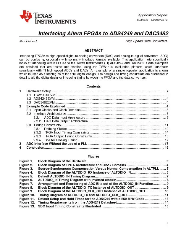
SLAA545 Figure 14SDC Output Timing Constraints IllustratedIntroductionInterfacing FPGAs to highspeed digitalanalog converters DAC and analogdigital converters ADC can be confusing especially wit ID: 299119

SLAA545 Figure 14.SDC Output Timing Constraints

Share:

Link:

Embed:

Download Presentation from below link

Download Pdf The PPT/PDF document "2 Interfacing Altera FPGAs to ADS4249 an..." is the property of its rightful owner. Permission is granted to download and print the materials on this web site for personal, non-commercial use only, and to display it on your personal computer provided you do not modify the materials and that you retain all copyright notices contained in the materials. By downloading content from our website, you accept the terms of this agreement.


Presentation Transcript

Application Report 1 �� &#x/Att;¬he; [/; ott;&#xom ];&#x/BBo;&#xx [3;�.35;g 3;.10;5 5;.06;&#x 46.;砉&#x ]/S;&#xubty;&#xpe /;oot;r /;&#xType;&#x /Pa;&#xgina;&#xtion;&#x 000;&#x/Att;¬he; [/; ott;&#xom ];&#x/BBo;&#xx [3;�.35;g 3;.10;5 5;.06;&#x 46.;砉&#x ]/S;&#xubty;&#xpe /;oot;r /;&#xType;&#x /Pa;&#xgina;&#xtion;&#x 000; &#x/MCI; 0 ;&#x/MCI; 0 ;SLAA545 October 2012 Interfacing Altera FPGAs to ADS4249 and MattGuibordHigh Speed DataConvertersABSTRACTInterfacing FPGAs to high speed digitalanalog converters (DAC) and analogdigital converters (ADC) . ContentsHardwareSetup FigureBlock Diagram of the ALTDDIO_RX InstanceALTDDIO_INFigureDefault ALTDDIO_INTimingDiagramFigureALTDDIO_IN Timing Diagram withInvertedFigureArrangement and Reordering of Bits out of theALTDDIO_INFunctionFigure SLAA545 2 Interfacing Altera FPGAs to ADS4249 and DAC3482 �� &#x/Att;¬he; [/; ott;&#xom ];&#x/BBo;&#xx [3;�.35;g 3;.18;5 5;.06;&#x 47.;蘈&#x ]/S;&#xubty;&#xpe /;oot;r /;&#xType;&#x /Pa;&#xgina;&#xtion;&#x 000;&#x/Att;¬he; [/; ott;&#xom ];&#x/BBo;&#xx [3;�.35;g 3;.18;5 5;.06;&#x 47.;蘈&#x ]/S;&#xubty;&#xpe /;oot;r /;&#xType;&#x /Pa;&#xgina;&#xtion;&#x 000; &#x/MCI; 0 ;&#x/MCI; 0 ;FigureSDC Output TimingConstraintsIllustratedIntroductionInterfacing FPGAs to highspeed digitalanalog converters (DAC) and analogdigital converters (ADC) can be confusing, especially with so many interface formats available. This application note is meant to clarify the interface between the Altera FPGAs and TI’s ADS4249 and DAC3482. The concepts shown in this application note extend to other TI highspeed data converters with similar interface formats.The ADS4249 is a dualchannel, 14bit, 250MSPS ADC with a dualbus, bytewise digital nterface.The ADS4249 interface example is applicable to many TI highspeed ADCs including the following families: ADS41XX, ADS42XX, and ADS62PXX.The DAC3482 is a dualchannel, 16bit, 1.25GSPS DAC with a singlebus, samplewise digital interface.The code example is designed for a data rate of 250 MSPS to the DAC allowing a simple interface between the ADC and DAC. The same concepts extend to cover most of TI’s LVDS, highspeed DACs at varying data rates.The provided code examples are tested and verified using the TSW1400 evaluation platform which is designed to interface seamlessly with TI’s highspeed ADC and DAC evaluation modules (EVMs).An example ofa simple repeater application is shown which can be used as a starting point for a full digital design. The design and timing constraints are discussed in detail to aid the digital designer in closing timing between the FPGA and data converters.HardwareSetupThe following sections describe the three main pieces of hardware. Figure 1 shows a block diagram of the hardware setup with the TSW1400, ADS4249, and DAC3482EVMs and the clock and signal sources. SLAA545 Interfacing Altera FPGAs to ADS4249 and DAC3482 3 �� &#x/Att;¬he; [/; ott;&#xom ];&#x/BBo;&#xx [3;�.35;g 3;.10;5 5;.06;&#x 46.;砉&#x ]/S;&#xubty;&#xpe /;oot;r /;&#xType;&#x /Pa;&#xgina;&#xtion;&#x 000;&#x/Att;¬he; [/; ott;&#xom ];&#x/BBo;&#xx [3;�.35;g 3;.10;5 5;.06;&#x 46.;砉&#x ]/S;&#xubty;&#xpe /;oot;r /;&#xType;&#x /Pa;&#xgina;&#xtion;&#x 000; &#x/MCI; 1 ;&#x/MCI; 1 ; &#x/MCI; 2 ;&#x/MCI; 2 ; &#x/MCI; 3 ;&#x/MCI; 3 ; &#x/MCI; 4 ;&#x/MCI; 4 ; &#x/MCI; 5 ;&#x/MCI; 5 ;FigureBlock Diagram of theHardwareTSW1400EVMThe code examples discussed in this application note are tested and verified on the TSW1400 data capture and pattern generation card. The TSW1400 captures digital data from ADCs and sources digital data to DACs. The TSW1400 contains connections for both ADC and DAC evaluation modules from TI. At the heart of the TSW1400 is the powerful Altera Stratix IV FPGA that supports sourcing and receiving 16bit parallel LVDS samples at rates up to 1600 MSPS. The LVDS receive lines are brought over to an HSMC connector that interfaces directly with TI’s highspeed ADC EVMs. Similarly, the LVDS transmit pins connect to an HSMC connector to interface with the TI highspeed DAC EVMs. Additionally, CMOS inputs and outputs are available on the TSW1400 for use with any of the TI highspeed CMOS ADCs or DACs.The TSW1400 also has a 1GB DDR2 memory module onboard that can store up to 512 M samples during data capture or for pattern sourcing. The example code discussed here does not make use of the memory. However, the High Speed Data Converter Pro (HSDCPro) software GUI makes full use of the memory interface for both DAC and ADC evaluation. SLAA545 ��4 &#x/MCI; 1 ;&#x/MCI; 1 ;1.2 ADS4249EVMThe ADS4249EVM allows evaluation of the ADS4249, a dual, 14bit, 250MSPS ADC. The ADS4249EVM allows the use of a singleended analog input that is converted to a differential signal by transformers. This allows for evaluation over a wide range of input frequencies from various signal sources. Additionally, the TSW1265EVMis available as a full receiver solution with a dualchannel downconverter, LMH6521 DVGA, and LMK04800 lownoise clock jitter cleaner for full system evaluation. For this application note, a 250MHz clock is provided to the ADS4249EVM from a signal generator through the CLKIN SMA connector. The ADS4249 then creates a 250MHz output clock that is synchronous with the output data. Both the clock and data are sent through the HSMC connector on the ADS4249EVM to the TSW1400.DAC3482EVMThe DAC3482 is a dual, 16bit, 1.25 GSPS DAC. The EVM allows evaluation of the DAC3482 with transformer coupled outputs and the CDCE62005 clock generator. Additionally, the TSW3085EVMis available, allowing the evaluation of the full transmit solution consisting of the DAC3482 driving the TRF3705 quadrature modulator and also includes the LMK04800 clocking solution. For the example code, a 1GHz clock is applied to the DAC3482EVM through the EXT_REF_CLK SMA input. The CDCE62005 receives the clock and distributes a 1GHz clock to the DAC and also divides the clock by four to send a 250MHz clock to the FPGA to create the transmit clock domain. The DAC3482 is setup with an interpolation of four and a data rate of 250 MSPS for a final DAC output rate of 1 GSExample CodeExplainedThe following sections will breakdown the example code in detail. A simplified block diagram of the example code is shown below in Figure 2FigureBlock Diagram of FPGA Architecture and ClockDomains SLAA545 Interfacing Altera FPGAs to ADS4249 and DAC3482 5 �� &#x/Att;¬he; [/; ott;&#xom ];&#x/BBo;&#xx [3;�.35;g 3;.10;5 5;.06;&#x 46.;砉&#x ]/S;&#xubty;&#xpe /;oot;r /;&#xType;&#x /Pa;&#xgina;&#xtion;&#x 000;&#x/Att;¬he; [/; ott;&#xom ];&#x/BBo;&#xx [3;�.35;g 3;.10;5 5;.06;&#x 46.;砉&#x ]/S;&#xubty;&#xpe /;oot;r /;&#xType;&#x /Pa;&#xgina;&#xtion;&#x 000; &#x/MCI; 1 ;&#x/MCI; 1 ; &#x/MCI; 2 ;&#x/MCI; 2 ; &#x/MCI; 3 ;&#x/MCI; 3 ;2.1 Input Clocks and ClockDomainsThere are two clocks sent to the FPGA in the example code which form two clock domains within the FPGA. The ADS4249 provides a 250MHz input clock for the receive domain from its sourcesynchronous data clock. The transmit side of the FPGA receives a 250MHz clock from the DAC3482EVM that is divided down by four from the 1GHz DAC output clock using the CDCE62005. Figure 2 shows the external clock sources and the clocks used throughout the design.Both input clocks are brought into phaselocked loops (PLL) which generate the internal clocks. On the RX side, the ADS4249 provides a centeraligned sourcesynchronous data and clock.For a sourcesynchronous interface, the goal of the FPGA is to keep the clockdata phase relationship seen at the input pins the same at the internal I/O registers, to maintain the maximum timing margin. Therefore, the RX PLL is setup to simply recreate the input clock using sourcesynchronous compensation mode and a 0° phase shift. Sourcesynchronous compensation mode maintains the phase relationship between the clock and data coming from the ADS4249 inside of the FPGA by matching the delay from the clock input pin to the I/O registers and the delay from the data input pins to the I/O registers.Note that a clock phase shift is not needed inside of the FPGA because the ADS4249 already provides a centeraligned data clock and the sourcesynchronous compensation of the FPGA’s PLL maintains this relationship. Figure 3 shows a block diagram of sourcesynchronous compensation in theFPGA.The TX side receives a clock from the DAC3482EVM that does not have data associated with it so sourcesynchronous mode is not needed, since there is no dataclock phase relationship to maintain. Therefore, the PLL on the TX side recreates the TX input clock with 0° phase shift, but normal compensation mode is used since there is no data associated with this clock. Normal compensation mode compensates for the delay introduced by the global clock network from the input pin to the register that is being clocked as shown in Figure 3. The 0° phase shift clock is used to clock data out of the RXTX FIFO and to clock data out of the FPGA to be sent to the DAC. The DAC3482 expects centeraligned data so the PLL is also used to create a clock that has a 90° phase shift relative to the 0° phase shift clock. The 90° phase shifted clock is used to create the TX output clock so that a 90° phase difference exists between the data and data clock. This creates a sourcesynchronous, centeraligned interface between the FPGA andDAC.FigureSourceSynchronous Compensation VersusNormal Compensation inALTPLL SLAA545 ��6 &#x/MCI; 1 ;&#x/MCI; 1 ;The clocks are supplied by lab signal generators that are synchronized by their 10MHz references so both RX and TX domains are frequency locked. Still, the phase relationship between the two clock sources is not known so a FIFO is needed to transfer the data between the clock domains. Realistically, the RX PLL could be used to create the clocks for the TX domain since both are running at 250 MHz. In this case, a FIFO is not needed because the phase relationship between the RX and TX clocks would be known. However, two separate clocks were chosen for this design because the FIFO provides an easy breaking point in the code to separate the interfaces.InterfaceArchitectures2.2.1ADC Data InputArchitectureThe ADC input interface is created by the ALTDDIO_IN Altera Megafunction. This block has double data rate (DDR) input registers that capture data on both the rising edge and falling edge of the input clock. Single data rate (SDR) data is clocked out of theblock on the rising edge of the input clock where dataout_l contains the data clocked in on the previous falling edge and contains the data clocked in on the current rising edge. Figure 4 shows the block diagram forthe ALTDDIO_IN function. For more information on the ALTDDIO_IN function, see the user’s guide.rx_pll_clk clock shown in Figure 4 should be used as the SDR clock for the rest of the designFigureBlock Diagram of the ALTDDIO_RX Instance ofALTDDIO_INThe default timing diagram for the ALTDDIO_IN function is shown in Figure 5 for the odd and even bits of the ADS4249. This timing diagram assumes that therehas been no phase shift of the clock between the ADS4249 and the ALTDDIO_IN function. This timing diagram shows that on the rising edge of the input clock the output dataout_l has the odd bits from the previous sample (sample N1) and the output has the even bits of the current sample (sample N). This means that the odd and even bits at the output of the function for each clock cycle are not from the same ADC sample. This creates a problem when trying to compile the DDR data into a single sample for processing. The problem is illustrated in Figure 5 Interfacing Altera FPGAs to ADS4249 and DAC3482 7 SLAA545 �� &#x/MCI; 1 ;&#x/MCI; 1 ; &#x/MCI; 2 ;&#x/MCI; 2 ; &#x/MCI; 3 ;&#x/MCI; 3 ; &#x/MCI; 4 ;&#x/MCI; 4 ;FigureDefault ALTDDIO_IN TimingDiagramThere are two ways to fix this problem; the first is to invert the input clock by applying a 180° phase shift in the PLL. The timing diagram for the inverted input clock is shown in Figure 6new diagram shows that the even and odd bits for the same sample are clocked out on the rising edge of the input clock with the even bitsdataout_l and the odd bits on . Notice that the even and odd bits have swapped outputs from the previous default case. This is the method used in the example code.Note that the PLL implementation in the example code does not have a 180° phaseshift as mentioned above. This phase shift is actually done external to the FPGA by physically swapping the differential traces on the layout of the EVM such that the positive output of the ADC goes to the negative input of the FPGA. Swapping the differentially traces is the same as inverting the signal (or applying a 180° phase shift) so that the clock coming into the FPGA is already inverted. Therefore, a 0° phase shift in the FPGA is sufficient to provide an inverted clock to the ALTDDIO_IN function. Without the physical inversion, the PLL needs to perform the phase shift.The second option is to delay the even bits on dataout_h from the previous sample by one clock cycle. This can be easily accomplished by creating a register that clocksin the even bits on the rising edge of the SDR clock. Once the even bits are delayed by one clock cycle, the matching odd bits will come out of the ALTDDIO_IN block on the next rising edge of the SDR clock. These can then be combined to form one ADC sampl SLAA545 ��8 &#x/MCI; 1 ;&#x/MCI; 1 ; &#x/MCI; 2 ;&#x/MCI; 2 ; &#x/MCI; 3 ;&#x/MCI; 3 ; &#x/MCI; 4 ;&#x/MCI; 4 ;FigureALTDDIO_IN Timing Diagram with InvertedThe ADS4249 uses two 7bit data buseswhere each bus contains one ADC channel with the even and odd bits for that channel interleaved so they are output on the rising and falling edge of the data clock, respectively. The example code uses a single ALTDDIO_IN function with 14 LVDS input pairs such that dataout_l dataout_h each contain 7 bits from channel A and 7 bits from channel B for 28 total bits output from the ALTDDIO_IN function on each clock rising edge. The arrangement of these bits is shown in Figure 7for the inverted clock case. For signal processing, these bits need to be rearranged into separate 14bit samples for channels A and B. A simple assign statement is used to put them in the correct order. The function of the assign statement is shown in Figure 7. Note that the ADS4249 is 14 bits while the DAC3482 is 16 bits. Two zeros are padded to the end of each 14bit sample so the 14 most significant bits of the DAC are used. If the delay method is used, the even and odd bits will be on dataout_h , respectively. Interfacing Altera FPGAs to ADS4249 and DAC3482 9 SLAA545 �� &#x/MCI; 1 ;&#x/MCI; 1 ; &#x/MCI; 2 ;&#x/MCI; 2 ; &#x/MCI; 3 ;&#x/MCI; 3 ; &#x/MCI; 4 ;&#x/MCI; 4 ; &#x/MCI; 5 ;&#x/MCI; 5 ;FigureArrangement and Reordering of Bits out of the ALTDDIO_INFunction2.2.2DAC Data OutputArchitectureFor the DAC, two ALTDDIO_OUT Altera Megafunctions are usedOne of the instances simply outputs the data and sync signals and the other instance creates the DDR output clock. The block diagram for the data output ALTDDIO_OUT function is shown in Figure 8datain_h port takes in the sample for channel A of the DAC and datain_l takes in the sample for channel B such that channel A is output on the rising edge of the clock and channel B on the falling edge.These samples come from the FIFO separating theRX and TX clock domains. There is an additional input for the DAC sync signal that is generated by pushing PUSHBUTTON1 with debounce code to prevent multiple sync instances. Notice that there is a zero as the last input bit which is necessary because a 17bit ALTDDIO_OUT function is not allowed. Therefore, an 18bit function is created and a dummy bit is used to allow the code to compile.FigureBlock Diagram of the ALTDDIO_TX Instance ofALTDDIO_OUT SLAA545 ��10 &#x/MCI; 1 ;&#x/MCI; 1 ;There is a second ALTDDIO_OUT instance that generates the output clock shown in Figure 9ALTDDIO_CLK_OUT simply takes in a 1 and 0 that it outputs on the rising and falling edge of tx_pll_output_clk, respectively. The output of this block becomes the data clock for the data transmitted to the DAC. Note that the clock for this block is the PLL clock that has a 90° phase shift compared to the data clock. This creates a centeraligned, sourcesynchronous interface as required by the DAC.FigureBlock Diagram of the ALTDDIO_CLK_OUT Instance ofALTDDIO_OUTThe timing diagram for these two blocks is shown in Figure 10, illustrating that tx_pll_output_clk has a 90° phase shift compared to tx_pll_data_clk. The data is clocked out on tx_pll_data_clk and the output clock is created from tx_pll_output_clk. At the bottom of the diagram, it is obvious that the data and output clock form a centeraligned sourcesynchronous output. The output clock is created using an ALTDDIO_OUT block, instead of using the PLL clock directly, because the DDR output blocks have more tightly matched delays to the output pins than the global clock network to the DDR output block. This eases the timing closure. Interfacing Altera FPGAs to ADS4249 and DAC3482 11 SLAA545 �� &#x/MCI; 1 ;&#x/MCI; 1 ; &#x/MCI; 2 ;&#x/MCI; 2 ;tx_pll_data_clktx_pll_output_clktx_chA_sampletx_chB_samplePUSHBUTTON1lvds_tx_data_clk_plvds_tx_port_plvds_tx_sync_pAn = channel A sample nBn = channel B sample nFigure 10. Timing Diagram of ALTDDIO_TX and ALTDDIO_CLK_OUTTimingConstraintsThe purpose of timing constraints is to describe the data to clock skew ofan external device that is interfacing with the FPGA. These constraints give the code synthesizer a valid clockskew target for the internal timing of the FPGA. The most important thing to remember is that it is the external interface that is being defined. This section only discusses timing constraints for sourcesynchronous interfaces such as those used with TI ADCs andDACs.For a device that is transmitting data to the FPGA, such as an ADC, the timing constraints define the amount of variation in skew that could exist between the data and data clock. First the latch and launch clocks are defined, where the launch clock represents the data transition edge and the latch clock represents the data clock. The clock definitions set the initial ideal timing between the data and clock. Then, minimum and maximum delays are defined that represent the maximum possible delay variation of the data lines. These delays essentially specify the valid data window around the latch clock. A0 A1 A2 B0 B1 B2 XX XX A0 B0 A1 B1 A2 B2 SLAA545 12 create_clock - name ADC_DATA_CLK - period 4.00 [g et_ports lvds_rx_clk_p] create_clock - name ADC_LAUNCH_CLK - period 4.00 - waveform {3 5} create_generated_clock - [get_pins {RX_PLL_inst|altpll_component|auto_generated|pll1|clk[0]}] For a device that is receiving data from the FPGA, such as a DAC, the timing constraints define the minimum time that the receiver requires the data to be valid before and after the latch clock edge in order to capture the data correctly. It can be thought of as defining the range of delays between the data and clock that the internal paths of the receiving device may introduce. The delays define the amount of time that the FPGA must guarantee that the data arrives before or after the latch clock to meet timing under all situations. Again, the clocks are defined first to give an ideal starting point and then delays are applied to define the time the receiver requires to capture valid data.The following sections assume familiarity with the Synopsis Design Constraint (SDC) format and TimeQuest Timing Analyzer. For an introduction and examples, please see the TimeQuest Timing Analyzer documentation on Altera’s website, www.altera.com . 2.3.1DefiningClocThe first step in setting up timing constraints is to define the external clocks for both the RX and TX domains. For the RX clock domain, the clock that exists at the actual FPGA input port is the data clock that is output from the ADC. This clock is defined as shown in the SDC line below.The period is set to 4 ns, assuming the ADS4249 is running at 250 MSPS, and the clock is applied to the lvds_rx_clk_p input port defined in the toplevel verilog file.Next, a virtual clock is created defining the ideal launch clock for the data coming out of the ADC. Since the ADC is a centeraligned interface, the launch clock needs to be advanced by 90° in order to obtain the correct initial setup and hold times. This is shown in the line below, where the waveform parameter defines the rising and falling edge position, respectively, where the default values are 0 ns and 2 ns for a 250MHz clock. Advancing the clock by 90° is equivalent to having the rising edge occur 1 ns sooner, so a value of 1 ns should work, however, the waveform parameter cannot have negative values. Since the waveform parameter understands that clocks are periodic, and then a value of 3 ns and 5 ns will be understood as 1 ns and1ns.Next, the ADC latch clock is manually created from the PLL output as shown below, rather than allowing the tool to do it automatically. This way, the name ADC_LATCH_CLK can be used in other statements rather than using the longer, automatically generated PLL clock name. These clock definitions must come before the derive_pll_clocks statement mentioned below. Interfacing Altera FPGAs to ADS4249 and DAC3482 13 SLAA545 derive_pll_clocks derive_clock_uncertainty Adding the two lines below automatically derives the clocks of the PLL that have not already been defined and calculates the clock uncertainty.Figure 11 shows the default setup and hold times of the clocks described above. There are four possible default setup and hold times that TimeQuest analyzes:rising edge to risingedgerising edge to fallingedgefalling edge to risingedgefalling edge to fallingedgeThe desired default setup time should be based on the rising edge to rising edge and falling edge to falling edge. The desired default hold time should be based on the rising edge to falling edge and falling edge to rising edge. Although TimeQuest analyzes all four cases for both setup and hold, only the two most restrictive cases are used to constrain timing. Two of the four cases are shown in Figure 11The shorter setup and hold times shown in Figure 11 are used because they are more restrictive than the longer setup and hold times. The SDC file in the example code contains set_false_path statements between the ADC latch and launch clocks that tell TimeQuest to ignore these extra setup and hold times which simplifies analysis and timing reporting, but they are not required for proper analysis.ADC_LAUNCH_CLKADC_DATA_CLK4 ns Correct default setup andhold times for a DDRinterfaceIncorrect default setup and hold times for a DDR interface, but these do not effect analysis because they are less restrictive (3 n�s 1 ns)Figure 11. Default Setup and Hold Times for the ADS4249 with a 250MHz Clock Hold (t hd ) Setup (t sd ) Hold (t hd ) 1 ns 1 ns 3 ns Setup (t sd ) 3 ns SLAA545 ��14 &#x/MCI; 1 ;&#x/MCI; 1 ; &#x/MCI; 2 ;&#x/MCI; 2 ;For the TX side, first the input clock from the DAC3482EVM needs to be added as shown below. This is the divided down clock that is sent fromthe DAC3482EVM back to the TSW1400 providing a clock for the TX clock domain. This clock is applied to the input port lvds_tx_fpga_clk_p and is used as the input clock for the TX_PLL block.Next, the DAC launch clock is manually created, rather than automatically through the derive_pll_clocks statement, allowing the use of a more convenient clock name as shown below. This way, the name DAC_LAUNCH_CLK is used in other statements to define the PLL output clock rather than using the longer automatically generated name. Both of these clock definitions must come before the derive_pll_clocks statement mentionedpreviously.Next, derive the PLL clocks and clock uncertainty as mentioned above, followed by the definition of the DAC data outputclock, shown below. The statement below defines the DAC data clock at the FPGA output port. Although this clock is generated by the ALTDDIO_CLOCK_OUT function, the source for the clock is the 90° phaseshifted PLL clock output. The ALTDDIO_CLOCK_OUT output is applied to the port lvds_tx_data_clk_pThe DAC_DATA_CLK and DAC_LAUNCH_CLK also have four possible default setup and hold times. The same argument applies here that only the two most restrictive setup and hold times are used. The set_false_path statements are added for these clocks to simplify analysis and reporting timing, but they are again optional. As in the ADS4249 case, the default setup and hold times on the TX side are both 1 ns, since it is a centeraligned interface.2.3.2FPGA Input TimingConstraintsOnce the external clocks are created, the delays must be defined based on the external devices. On the RX side first, the setup and hold times of the ADS4249 need to be pulled out of the datasheet.The excerpt in Figure 12 is taken from the timing requirements table in the ADS4249 datasheetThe ADC setup and holdtime parameters define the datavalid window around the clock zerocrossing point and represent the window of time that the FPGA can use to meet timing. The data setup time represents the time before the clock edge that the data is valid and the hold time represents the time after the clock edge that the data is valid. The minimum values, shown on the left side for each parameter, are the most useful because they are valid over temperature and account for bitbit skew.Figure 12. Timing Requirements from the ADS4249 Datasheet create_clock - name TX_FPGA_CLK - period 4.00 [get_ports lvds_tx _fpga_clk_p] create_generated_clock - [get_pins {TX_PLL_inst|altpll_component|auto_generated|pll1|clk[0]}] create_generated_clock - [get_ports lvds_tx_data_clk_p] Interfacing Altera FPGAs to ADS4249 and DAC3482 15 SLAA545 �� &#x/MCI; 0 ;&#x/MCI; 0 ; &#x/MCI; 1 ;&#x/MCI; 1 ; &#x/MCI; 3 ;&#x/MCI; 3 ;Figure 13 provides a graphical view of the ADC setup and hold times as well as the input delays that must be defined. In the figure, the green blocks represent the total skew that the FPGA is allowed to introduce internally and the red blocks represent the maximum and minimum delays that the ADC may introduce on the data line.Figure 13. SDC Input Timing Constraints IllustratedSince the ADC setup and hold times define the data valid window around the data clock, it is fairly intuitive that the rest of the clock period is consumed by the ADC in the form of delays on the data line. The input timing delays defined in the SDC file then specify the possible range of data delays the ADC could introduce. Therefore the min and max delays are defined as equation 1 and equation 2 below. The variables used in the equations are defined in Figure 13These equations assume that the data and clock traces on the board are well matched. This is a valid assumption with the TSW1400 and ADS4249EVM where the traces are matched within 10 mils. If a data trace is longer than the clock trace then that reduces the setup time and increases the hold time so the max delay increases and the min delay decreases accordingly. If the clock trace is longer than the data trace, then that reduces the hold time and increases the setup time so the min delay increases (becomes more negative) and the max delay decreases accordingly. SLAA545 16 2.3.3FPGA Output TimingConstraintsOne simple way to think about the output timing delays is to imagine them as defining the data delay inside of the receiving device before they reach the latching register. This essentially says that the delays specify the minimum amount of time the receiver needs the data held constant around the latching clock in order for the data to be at the latching register in time for the clock to capture the data successfully. Knowing this, the timing delays are very straightforward for a DAC. The DAC setup and hold times listed in the datasheet specify the amount of time that the DAC needs to receive data before the clock edge and the time the DAC needs the data held constant after the clock edge, respectively. Therefore, it is very straightforward that the maximum output delay is simply the setup time of the DAC and the minimum output delay is the negative of the hold time of the DAC. This is illustrated in Figure 14Again, these delays are only valid if the data and clock lines are matched precisely, such as with the DAC3482EVM and TSW1400. If there is mismatch between the traces, the delays need to be accounted for. If the data trace is longer than the clock trace, then the max delay increases and the min delay decreases accordingly. If the clock trace is longer than the data trace then the max delay decreases and the minimum delay increases.Figure 14. SDC Output Timing Constraints Illustrated Interfacing Altera FPGAs to ADS4249 and DAC3482 17 SLAA545 �� &#x/MCI; 0 ;&#x/MCI; 0 ; &#x/MCI; 1 ;&#x/MCI; 1 ; &#x/MCI; 2 ;&#x/MCI; 2 ; &#x/MCI; 3 ;&#x/MCI; 3 ;2.3.4Tips for Closing TimingIf the designer is having trouble closing timing there are a few simple things that can be tried. First, the PLL of both the RX and TX side can be used to introduce a phase shift inside the FPGA to increase setup or hold times. By adding a delay on the latch clock, the default setup time is increased and the default hold time is decreased. This should help to improve the setup slack in the case where the setup timing has little slack but the hold timing has a lot of slack.Alternatively, a negative phase shift can be added to the latch clock to increase hold slack and decrease setup slack. Similarly, the TX PLL can add more or less phase difference between the 0° launch clock and the 90° latch clock to improve the setup and hold times at the DAC.Note that changing the PLL clockphase shifts does not affect the SDC timing constraints because only the internal timing has changed while the external timing has remained the same. Remember that the SDC file describes the external interface timing only.The devices often allow even more flexibility. For instance, the DAC3482 allows programming in different setup and hold times, effectively shifting the required data window around the data clock. This may be especially useful for closing timing at sample rates higher than 250 MSPS. The ADS4249 has similar features in which the rising and falling clock edges can be shifted in time, but not as extensive as the DAC3482.ADC Interface Without the use of aPLLIt is easy to consume all of the FPGA’s PLLs when interfacing many devices with it. In these situations, it is desirable to avoid the use of PLLs for the receiving devices. It is possible to bring the clock into the FPGA and use it directly at the ALTDDIO_IN block. The caveat is that the clockdata relationship is no longer maintained within the FPGA as it was when using a PLL with sourcesynchronous compensation. Therefore, the FPGA must match the delays between the clock and data lines to meet the necessary timing for a centeraligned interface. This should be possible since the FPGA I/O cells have adjustable data delays. If the timing constraints are set correctly, the fitter should be able to match the delays between the clock and data traces.This will create a fairly robust solution because the matched delays should vary similarly over process, voltage, and temperature differences.If timing cannot be met or timing is met with marginal results, the clock shifting feature of the ADS4249 can be used tomove the clock edge compared to the data to loosen the matching requirement inside of the FPGA. If this is done, then the timing constraints will need to be updated to match the new timing of the ADC interface. The easiest way to do this is to simply modify the waveform property of the ADC launch clock. Since it is the ADC latch clock (data clock) that is actually being shifted, an advance of the latch clock is equivalent to a delay on the launch clock. Simply add the amount of time that the latch clock has been advanced to thewaveform values of the launch clock. Likewise, a separate waveform parameter could be defined for the latch clock (ADC_DATA_CLK) to shift the latch clock edge. SLAA545 ��18 &#x/MCI; 0 ;&#x/MCI; 0 ; &#x/MCI; 1 ;&#x/MCI; 1 ;4 ConclusionThis application note illustrates examples of both an ADC and a DAC interfacing with an Altera FPGA. The ADC is the ADS4249, a 250MSPS, 14bit ADC. The DAC is the DAC3482, a 1.25GSPS, 16bit DAC. The TSW1400 data capture and pattern generation card is used as a development platform for these interfaces. For both devices, the FPGA interface architecture is described in detail giving a solid comprehension of the design. The timing constraints for both interfaces are discussed and diagrams are shown providing a more intuitive understanding.Example code is provided as a working example for implementation into an existing FPGA or for further expansion using the TSW1400 as the development platform.1 ADS4249 DatasheetSBAS534C ) 2 DAC3482 DatasheetSLAS748D ) 3 TSW1400 User Guide (SLWU079A ) 4 TSW1265 User GuideSLAU429 ) 5 TSW3085 User GuideSLAU364 ) 6 PhaseLocked Loop (ALTPLL) Megafunction User Guide http://www.altera.com/literature/ug/ug_altpll.pdf ) 7 Double Data Rate I/O (ALTDDIO_IN, ALTDDIO_OUT, and ALTDDIO_BIDIR) Megafunctions User Guide (http://www.altera.com/literature/ug/ug_altddio.pdf ) IMPORTANTNOTICEANDDISCLAIMERTIPROVIDESTECHNICALANDRELIABILITYDATA(INCLUDINGDATASHEETS),DESIGNRESOURCES(INCLUDINGREFERENCEDESIGNS),APPLICATIONOROTHERDESIGNADVICE,WEBTOOLS,SAFETYINFORMATION,ANDOTHERRESOURCES“ASIS”ANDWITHALLFAULTS,ANDDISCLAIMSALLWARRANTIES,EXPRESSANDIMPLIED,INCLUDINGWITHOUTLIMITATIONANYIMPLIEDWARRANTIESOFMERCHANTABILITY,FITNESSFORAPARTICULARPURPOSEORNON-INFRINGEMENTOFTHIRDPARTYINTELLECTUALPROPERTYRIGHTS.TheseresourcesareintendedforskilleddevelopersdesigningwithTIproducts.Youaresolelyresponsiblefor(1)selectingtheappropriateTIproductsforyourapplication,(2)designing,validatingandtestingyourapplication,and(3)ensuringyourapplicationmeetsapplicablestandards,andanyothersafety,security,orotherrequirements.Theseresourcesaresubjecttochangewithoutnotice.TIgrantsyoupermissiontousetheseresourcesonlyfordevelopmentofanapplicationthatusestheTIproductsdescribedintheresource.Otherreproductionanddisplayoftheseresourcesisprohibited.NolicenseisgrantedtoanyotherTIintellectualpropertyrightortoanythirdpartyintellectualpropertyright.TIdisclaimsresponsibilityfor,andyouwillfullyindemnifyTIanditsrepresentativesagainst,anyclaims,damages,costs,losses,andliabilitiesarisingoutofyouruseoftheseresources.TI’sproductsareprovidedsubjecttoTI’sTermsofSale()orotherapplicabletermsavailableeitheronorprovidedinconjunctionwithsuchTIproducts.TI’sprovisionoftheseresourcesdoesnotexpandorotherwisealterTI’sapplicablewarrantiesorwarrantydisclaimersforTIproducts.MailingAddress:TexasInstruments,PostOfficeBox655303,Dallas,Texas75265Copyright©2019,TexasInstrumentsIncorporated