PDF-December, 2013, Singapore Numerical modeling on concrete debris ricoch
Author : celsa-spraggs | Published Date : 2016-07-24
applicable for the present study and a new criterion should be employed to define the Numerical model of impact All numerical simulation works in this study are
Presentation Embed Code
Download Presentation
Download Presentation The PPT/PDF document "December, 2013, Singapore Numerical mode..." is the property of its rightful owner. Permission is granted to download and print the materials on this website for personal, non-commercial use only, and to display it on your personal computer provided you do not modify the materials and that you retain all copyright notices contained in the materials. By downloading content from our website, you accept the terms of this agreement.
December, 2013, Singapore Numerical modeling on concrete debris ricoch: Transcript
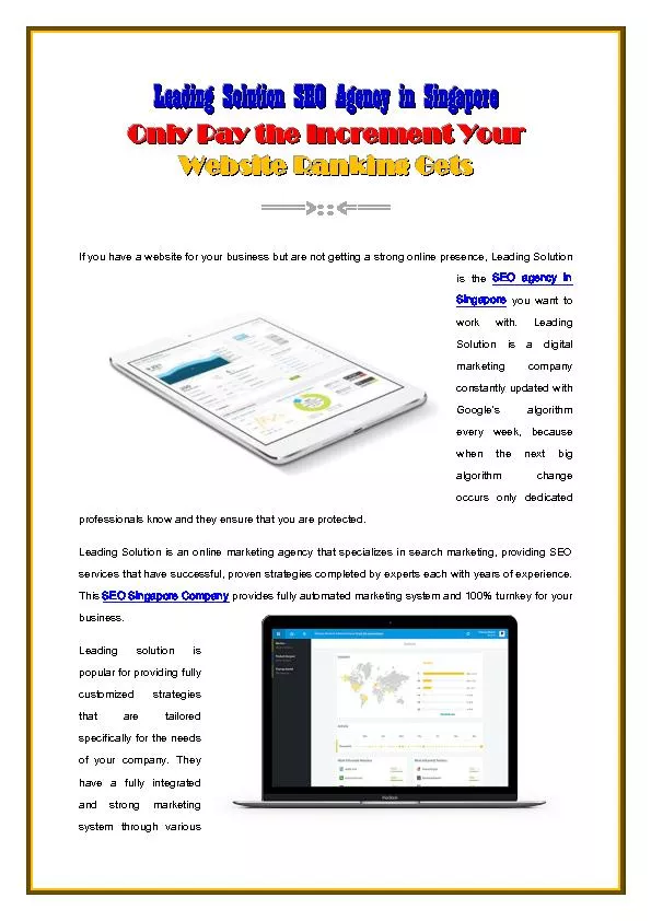
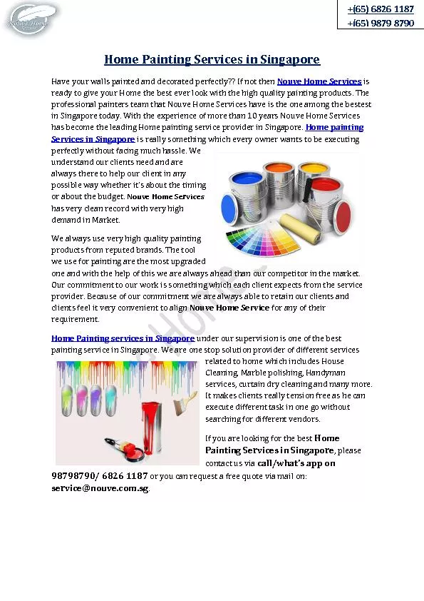
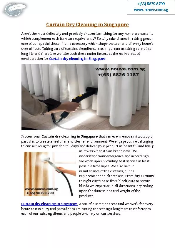
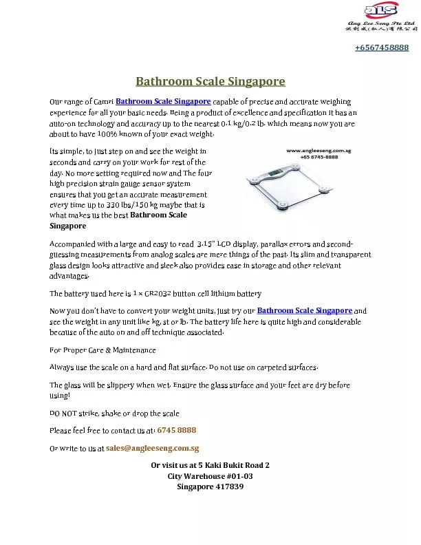
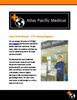
applicable for the present study and a new criterion should be employed to define the Numerical model of impact All numerical simulation works in this study are carried out by using the commercial sof. http://www.artisticconcretegroup.com/ Our dedication to quality, combined with the characteristic beauty and strength of our products, make our slogan a reality: It's not an expense; It's an investment! And yes, we remain customer service fanatics. Looking for best science, chemistry, English, GP, JC, economics, physics, O level and secondary school tuitions in Singapore? Visit us today at Home Tuition SG. By Assoc. Prof. Gary F. Bell. 1. The CISG is almost never applied in Singapore.. 2. Why it is never applied?. a. Singapore lawyers exclude it. . b. England has not adopted the CISG.. c. Singapore’s reservation under article 95.. . debris. . disks. with. . GRaTeR. . (Grenoble Radiative . TransfeR. ). Jérémy Lebreton. EXOZODI . Kick-off. Meeting . 10-02-2011. Different. and . complementary. . approaches. to model . debris. Leading Solution is the leading digital marketing agency providing current strategies for effective SEO to attain effective and efficient results for more profits and higher margins. They are willing to consult you on a non-obligation basis. An ICON for Butterflies of Singapore. Ours to Cherish, Ours to Protect. Vote for Singapore’s National Butterfly. Voting Dates. : 21-Mar to 30-Apr 2015. www.nationalbutterfly.org.sg. . Voters of the winning entry are automatically entered into lucky draw!. https://www.nouve.com.sg/paint.html | Are you looking for someone who has a very vast experience of house painting services in Singapore? Nouve Home Cleaning Services will fulfil your requirement. Nouve Teams each member has more than 10 years of experience and all are very professional in their work. https://www.nouve.com.sg/curtain.html | No one can does it better than Nouve home Solutions when it comes for curtain cleaning services in Singapore. We are professional in cleaning and offer our quality services at a very affordable price. http://angleeseng.com.sg/camry-digital-bathroom-scale-150kg | Track your weight loss with camry digital bathroom scale singapore featuring auto-on technology and accuracy up to the nearest 0.1 kg/0.2 lb. 4 High Precision Strain Gauge Sensor System http://ultimatelaundry.sg | We are offering laundry service singapore delivery, best laundry service, good laundry service singapore, best curtain cleaning in singapore. https://www.helphealsg.com | Physiotherapy, Helphealsg Sports and Spine Clinic, Occupational therapy, Sports Massage, Home therapy service in singapore. https://filetrip.net/view?GyteHc1Qit Atlas Pacific Medical consults and performs STD/HIV tests in Singapore. Our experienced male and female doctors will give you expert advice on the symptoms that you may be having, and provide a treatment plan for you. Visit: https://atlaspacificmedical.com/ Atlas Pacific Medical consults and performs STD/HIV tests in Singapore. Our experienced male and female doctors will give you expert advice on the symptoms that you may be having, and provide a treatment plan for you. Visit: https://atlaspacificmedical.com/
Download Document
Here is the link to download the presentation.
"December, 2013, Singapore Numerical modeling on concrete debris ricoch"The content belongs to its owner. You may download and print it for personal use, without modification, and keep all copyright notices. By downloading, you agree to these terms.
Related Documents