/
IGURE  The development of the buttressed core structur IGURE  The development of the buttressed core structur

IGURE The development of the buttressed core structur - PDF document

celsa-spraggs
celsa-spraggs . @celsa-spraggs
Follow
419 views
Uploaded On 2015-05-10

IGURE The development of the buttressed core structur - PPT Presentation

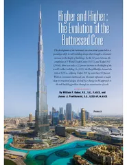
In the 32 years between the completion of 1 World Trade Center 1972 and Taipei 101 2004 there was only a 22 percent increase in the height of the worlds tallest building In 2010 the Burj Khalifa claimed the title at 828 m eclipsing Taipei 101 by mor ID: 64437

the years

Share:

Link:

Embed:

Download Presentation from below link

Download Pdf The PPT/PDF document "IGURE The development of the buttressed..." is the property of its rightful owner. Permission is granted to download and print the materials on this web site for personal, non-commercial use only, and to display it on your personal computer provided you do not modify the materials and that you retain all copyright notices contained in the materials. By downloading content from our website, you accept the terms of this agreement.


Presentation Transcript

F The development of the buttressed core structural system led to a paradigm shift in tall building design that brought a dramatic increase in the height of buildings. In the 32 years between the completion of 1 World Trade Center (1972) and Taipei 101 (2004), there was only a 22 percent increase in the height of the worlds tallest building. In 2010, the Burj Khalifa claimed the title at 828 m, eclipsing Taipei 101 by more than 60 percent. With its innovative buttressed core, the tower represents a major leap in structural design, elicited by a change in the approach to the tall building problem through an examination of scale. By William F. Baker, P.E., S.E., F.ASCE, and James J. Pawlikowski, S.E., LEED AP, M.ASCE The Evolution of the HROUGHOUT THE HISTORY of tall vented the means to go higher. In the 1970s Fazlur R. Khan’s tube concept ditional portal frame system used on such structures as the Empire State Building. Later develop-ments, including the core plus outrigger system, also provided architects with the tools to design taller, more efcient buildings. However, the re-marking a point on the progressive scale of the The buttressed core is a different species. Permitting a dramatic increase in height, its als and construction techniques and was not precipitated by a change tion technology. The es-sence of the system is a tripod-shaped structure in which a strong central core anchors three building wings. It is an inherently stable system in that each wing is buttressed by the other two. The central core provides the torsional resistance for the building, while the wings pro-vide the shear resistance and increased moment of inertia (see gure 1, typical oor plan velopment began with Tower go-based Skidmore, Owings 2004, Tow-er Palace III, located in Seoul, South Korea, promoted a new 2). Its tripartite arrangement provides 120 degrees between views and privacy. Although Chicago’s Lake Point Tower set the architectural precedent for the residential high-rise, the design of Tower Palace III tial tower.Tower Palace III was originally designed at more than 90 stories, its height supported by a Y-shaped oor plan. Because its architectural design called for elevators within the oval oor plate of each wing, engineers opted to connect the elevators via a central cluster of cores (parts a and b of gure 3). In doing so, the “hub” became the primary lateral system of the building. At the two upper me-chanical oors, the perimeter columns also were engaged to assist in resisting lateral loads by means of virtual outriggers (oor plates above and below in conjunction with a perimeter belt tions, these virtual outriggers spared the cally associated with direct Throughout the tural behavior and performed well in the wind tunnel, and it neering team that the struc-ture could go much higher. However, because of zoning is-sues, the design of the tower’s tallest wing was cut from 93 to 73 stories (the other wings sate for the loss of area). De-spite the decrease in height, team with the opportunity to explore a new approach to the tall building problem. Given Tower Palace III’s efficiency, ferred that, if a project had a sufciently large parcel, this In early 2003, soon af-ter completing the design of Tower Palace III, was supertall building in Dubayy ed Arab Emirates. (See “The SOM 0885-7024/12-0010-0058/$30.00 PER ARTICLE OCTOBER Burj Khalifa Triumphs” by William F. Baker, P.E., S.E., F.ASCE March 2010, pages 44–55.) On March 1 of that year, the team went to New York to be interviewed for the project, and it was agreed there that a brief idea competition and various other invited teams. Given the success of Tower Palace veloped to even greater heights, the team elected to use this structural system for what would later become the Burj engineers made critical changes to the Tower Palace III design that were essential to the evolution of the Burj Khalifa’s buttressed core. The design of the tower’s central core ar-proach successfully t all of the tower’s elevators and operating systems within the core while maintaining good structural behavior. In contrast to the case of Tow-er Palace III, Burj Khalifa’s central core houses all ver-tical transportation with the exception of egress stairs Each of the three wings forming the Burj Khalifa’s buttressed core is on a 9 m module. As in Tower Palace III, the walls in each wing of the Burj Khalifa were a way as to separate the living kitchen components. This provided sions were much greater. This plan later merous doors in the structure and little exibil-ity in unit layout. It was thus difcult to comply bility to natural light in the kitchen. As a result, the team embarked on a series of studies to see if the central core ing a round of parametric studies carried out in the autumn of 2003, it was clear that the central core had enough strength and stiffness to serve as the building’s torsional hub. Also in 2003, the wing walls were adjusted so that the primary walls now lined the corridors at the center of each wing, instead of protruding into the units. Besides improving the efciency of the units, this adjustment improved the efciency of the Studies were also carried out to assess the possibility of eliminating the perimeter columns by using cantilever beams was selected to design the Burj 60] Civil Engineering OCTOBER2012 FALL FOUR Khalifa, the engineering team immediately tested the tower’s initial geometry in the wind tunnel, only to discover that it had large movements and base moments.sults were more closely related to the geometry tural system. Therefore, the dynamic proper-ties of the structure were manipulated in or-der to minimize the harmonics with the complish this by essentially “tuning” the building as if it were a musical instrument in order to avoid the aerodynamic harmonics that are A key component of the Burj Khalifa’s structural gravity.” This meant loads to where they would be most use-tower’s setbacks in such a way that the nose of the tier above sat on the cross-walls of the tier below, yielding great benets for both tower strength and economy. Engineers also employed a series of “rules” to simplify load paths and construction. These included a rigorous 9 m module nel as the geometry of the tower evolved and as the tower was rened architectur-ally, the setbacks in the three wings fol-lowing a clockwise pattern (in contrast to the counterclockwise pattern in the original scheme). After each round of wind tunnel testing, to minimize the wind ef-unrelated changes in the client’s program. In general, the num-ber and spacing of the setbacks changed, as did The designers also noticed that the force spectra for cer-OCTOBER2012 less excitation in the important frequency range when winds impacted the pointed, or nose, end entation of the tower relative to the most frequent directions of strong wind in Dubayy, which are from the northwest, south, and east. The careful selection of the tower’s orientation, along with its variant setbacks, resulted in substantial reduc-tion of wind forces. By “confusing” the wind, the design encourages disorganized vortex shedding In order to have an efcient supertall building, it is best to use all the vertical elements for both gravity and wind loads. In order to achieve this on the Burj Khalifa, it was necessary to engage cause of the tower’s extreme height, the virtual outrigger used on Tower Palace III was replaced by a direct outrigger. In addition to engaging the perimeter for lateral load resistance, the outrig-gers allow the columns and walls to redistribute loads several times throughout the building’s ening between the columns and the core. By the time the building meets the ground, the loads in the walls are somewhat ordinary, and in contrast umns at the base are massive, most of the Burj Khalifa’s base columns are relatively thin and The Burj Khalifa’s structural system was cre-ated with a conscious effort to conform to and 62] Civil Engineering OCTOBER2012 The Burj Khalifas structural system was created with a conscious effort to conform to and complement current construction technology. complement current construction technology. The goal was to use a highly organized system with conventional elements that would provide a high repetition of formwork. Initially the team contemplated a composite oor framing system, as cided that the all-concrete scheme was more appropriate and economical. Although the tower’s oor plate changes as the structure ascends, the segments near the core repeat them-selves for as much as 160 levels. As the loads accumulate from The design of Las Vegas Tower (Crown Las Vegas) marked the next step in the evolution of the buttressed core. In early began working on the design of a 575 m hotel tower located on the Las Vegas Strip (see gure 9). As in its predecessors, each of the tower’s three wings but-tresses the other via a central core. However, rather than stepped set-backs, Las Vegas Tower has a shape that er’s width to continually vary. In this way, wind vortices never get organized. Furthermore, continual changes in the tower’s footprint required the loads to be moved to other elements besides the wing walls. This was accomplished by locating the stair at the end of the corri-dor (see gure 10). The concrete around the stair, somewhat like the chord of a truss, acts as a major structural ele-ment but moves toward the center of the building as it tapers at the top. In this way it does not require the stair transfers that were necessary in the Burj Khalifa and permits a much smoother load transfer than a solution that relies OCTOBER2012 However, rather than stepped setbacks, Las Vegas Tower has a shape that changes in elevation, causing the towers width to continually vary. 10 on setbacks. The stair core also provides for a large amount of cantly increasing the tower’s moment of inertia. However, the system is similar to the Burj Khalifa in that it employs direct outriggers connecting the perimeter columns to the interior core walls at each mechanical oor. (The project was embarked on a design competition for what is set to be the next world’s tallest building, Kingdom Tower, use tower’s elongated, triangular shape is a direct descendant of the Tower Palace III, Burj Khalifa, and Las Vegas Tower paradigm and is derived from an optimized structural form for strength and wind performance (see gure 11). Referred to as the stayed buttressed core, this structural system was de-veloped from an extensive analysis of the construction history proposed two schemes for this tower, one with col-umns and one without. The scheme with columns is similar to that used for the Burj Khalifa: columns of the perimeter blade type located in line with interior transverse core wall elements. Like their predecessors, these columns required 64] Civil Engineering OCTOBER2012 11 linkage to the core via direct outriggers, although distributed link beams also were considered. Early in the design process, it was realized that there was an opportunity to create the nate these columns and, with them, the outriggers, ciency. A rigorous study was conducted to deter-mine the optimum wall geometry with respect to system efciency and stiffness (see gure 12). Thus, the column-free scheme was born. Like the system considered in 2003 for the Burj Khalifa, this system used a central structural core with short transverse walls that continue into each of the three wings, supporting cantilevered oors and a column-free perimeter (gure 13). Stairs with surrounding walls are located at the end of each wing and scale back a nominal amount at each level to establish the building’s taper, there-by eliminating any setbacks. The tripartite floor geometry, in low lease span, pro-taking structure of unencumbered space that in its oramic views realizes the full potential of the buttressed core Because of the amazing stiffness of en-gineers were able to scale the system ties per square meter as in the Burj Khalifa, which is already very efcient. This new structural system also eliminates the need for outriggers and perimeter columns and is easily constructed within a standardized formwork system, thus greatly simplifying and accelerating construc-tion. Tapering as they rise, the symmetrical internal core elements are sized to maximize their footprint and allow the building to move loads efciently to the ground while shortening the construction umns, complex outrigger trusses, and similar trans-The evolution of the buttressed core traces the development of a simple yet powerful structur-priate and successful system for each of the buildings described here. With each build-ecting both its exibility and its potential. The buttressed core has evolved into a system rates the ideals of structural efcien-cy, constructabil-ity, and architec-tural function and William F. Baker, P.E., S.E., F.,ASCE, is a partner of Skidmore, Owings & Merrill in Chicago, and James J. Pawlikow-S.E., LEED AP, M.ASCEOCTOBER201201265]SOM ©JILL PAIDER, A rigorous study was conducted to determine the optimum wall geometry with respect to system ef“ciency and stiffness. Thus, the column-free scheme was born. Baker Pawlikowski 12 13