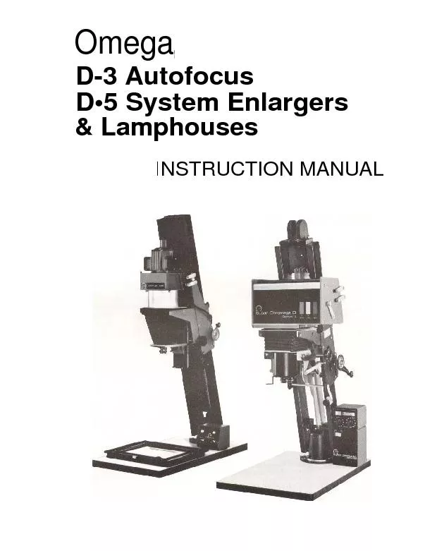
/
Omega,D-3 AutofocusD Omega,D-3 AutofocusD

Omega,D-3 AutofocusD - PDF document

celsa-spraggs
celsa-spraggs . @celsa-spraggs
Follow
376 views
Uploaded On 2016-03-21

Omega,D-3 AutofocusD - PPT Presentation

Insert the NegativePlace a negative emulsion side down in the carrier and insert carrier into enlargerFocus10Switch to white light mode Open lens diaphragm tomaximum opening Switch enlarger on ID: 264376

Insert the Negative:Place negative

Share:

Link:

Embed:

Download Presentation from below link

Download Pdf The PPT/PDF document "Omega,D-3 AutofocusD" is the property of its rightful owner. Permission is granted to download and print the materials on this web site for personal, non-commercial use only, and to display it on your personal computer provided you do not modify the materials and that you retain all copyright notices contained in the materials. By downloading content from our website, you accept the terms of this agreement.


Presentation Transcript

Omega,D-3 AutofocusD•5 System Enlargers& LamphousesINSTRUCTION MANUAL Insert the Negative:Place a negative, emulsion side down, in the carrier and in-sert carrier into enlarger.Focus10*Switch to white light mode. Open lens diaphragm tomaximum opening. Switch enlarger on.*Raise projector to its highest point by turning the magni-fication crank.*Use manual focus knob to focus sharply on white paperplaced on 1" high easel. Focusing from now on is auto-matic, except that minor corrections may be occasionallynecessary when glassless carriers are used.Adjustment MagnificationLoosen projector lock and move projector up or down thegirders by turning magnification control crank.Installing TracksRaise projector assembly to its highest point by turningcrank and tighten projector lock. Turn fine focusingknob in a counterclockwise position until lens stage isat its lowest point. Lift up focusing roller and arrest itin this position by turning lock-out lever in a clockwisedirection. Loosen knurled screw A, turn lock lever B ofcam pin in a clockwise direction and withdraw cam pin.Insert track with wide side on top and curved side infront. Curved side must pass behind shaft of front rollers.Straight rear edge is inserted in slots of nylon bearings,upper slot of track engages one of the slots in uppercross brace.4CAM PINInsert cam pin. Flat side must be parallel to slot intrack. Lock lever must be vertical after cam pin iscompletely inserted, be sure that track engages oneof its three grooves. Turn lock lever!14of a turn ina counter-clockwise direction and tighten knurledacre w.5Push track as high aspossible and swing lowerend rearwards, (i.e., intothe enlarger structure) until the lower slot of the track isopposite a corresponding slot of thelower track support, then let trackdrop slightly. 6Ifthe enlarger is equipped with more than one lens,more than one track is inserted in precisely the samemanner. In order to cause all tracks to simultaneouslyengage their respective grooves on the cam pin, theymay be held between the fingersofthe right hand asshown on the cam pin can then be given Xofa turnand locked by meansofscrew.DICHROIC LAMPHOUSEOPERATIONOperating Dichroic enlargers is the same as previously ex-plained for the condenser models. Since a Dichroic Lamp-house does not use condensers, the following explains theuse of the Dichroic Lamphouse for both color and blackand white printing.DIALING FILTRATIONFiltration is set by merely turning the filter thumb wheelsat the bottom of the lamphouse until the desired filtrationis indicated on the illuminated color coded digital readouts.These readouts indicate filtration to 0.01. The thumbwheelshave been positioned at the bottom of the lamphouse forconvenient operation even when the lamphouse is fullyelevated, at maximum magnification.Less than one revolution of thumbwheel dials full 0-168filtration range.PROGRAM MATCHINGADJUSTABLE DIGITAL READOUTSIn commercial laboratories using off-easel analyzing andmultiple enlarging stations, it is highly desirable to be ableto "fine tune" or calibrate the enlarger filters to a standardreference after changing lamps, or to compensate forvariations in emulsions in different paper lots. This caneasily be done with the Model II lamphouse, which avoidsthe need to re-analyze numerous negatives. Proceed asfollows:a)You have previously programmed your analyzer by mak-ing a good print from a master negative and recording thefilterpack used to make that print. For an example,assume that the correct filtration was 50 magenta and100 yellow.b) You have now replaced the enlarger lamp or perhaps en-countered a significant change in the paper emulsion,thus voiding the above filter information.c)Make a new test print from the same master negative, andwhen you again have an acceptable print, note the settingson the filtration readout. Assume they now read 70magenta, 90 yellow. You can now re-set the readouts toread 50M, 100Y which will permit you to continueprinting using the filter information noted on your pre-analyzed negatives. Re-setting the readouts is describedin the following:1.Knurled screws holding ledge (2)2.Removable aluminum ledge3.Removable cover panel4.Lshaped rod for declutching counter5.Alia®ys reset right digital wheel only6.Panel Lamp SwitchDichroicLamphouseOperating Partsand Controls. RESETTING READOUTS(From the previous example, readouts indicate 70M, 90Y,which you wish to reset to 50M, 100Y).1.While holding the aluminum ledge at the bottom of thelamphouse below, the readout windows, slowly removethe two knurled thumb screws in front of the filter con-trolwheels and remove the ledge and the front accessplate, exposing the readout assemblies.2. Pull out the L shaped counter release rod fully, andapply a slight downward,ard pressure on the rod to disen-gage the digital wheels from their transmission gears.While maintaining the downward pressure on the rod todisengage the digital wheels from their transmission gears.While maintaining the downward pressure on the rod, ad-just the right digital wheel of the three-wheel counterassemblies until the desired filtration is indicated. (Forexample, advance the Yellow readout 10 digits from 90to 100, and back off the Magenta readout - 20 pointsfrom 70M to 50M. Do not move the filter controls atunderside of the lamphouse).3.Remove finger pressure from the release rod and permitit to re-engage the counters with their transmission gears.Push the rod back into place and replace the frontcover, ledge, and knurled retaining screws.4. The lamphouse has not been recalibrated to the settingsused to program the analyzer. Note that you have notchanged the actual position of the Dichroics (which areat 70M, 90Y), but have merely "tuned" the readouts tocompensate for the change).5.When you wish to return the filter system to theoriginal zero settings, turn the filter controls downwardto their lowest settings (pure white light), and, asdescribed above, remove the access cover and reset allcounters to "000".LIGHT MODE SELECTORThe lever at the side of the lamphouse selects desired opera-ting mode: HIGH, LOW or WHITE LIGHT. Selected modeis shown on illuminated indicator on front panel.Use HIGH position for normal printing.The LOW position reduces light output by about two f /stopswithout Significantly large color shifts. Use this mode whenmaking small enlargements when exposure times wouldotherwisebe so short as to risk reciprocity failure.For focusing, scaling, and composition, or black and whiteprinting, switch to WHITE LIGHT. This retracts the filtersfrom the light path for bright and accurate focusing.Switching the lever back to either HIGH or LOW positionrestores the previously dial filtration settings. (See Figure 2,Item 5).12PANEL ILLUMINATIONThe panel lamp illuminates the light mode indicator, filtra-tion readouts, and readout color identification strips. Awhite slide switch at the underside of the lamphouse per-mits you to turn off this lamp. While our tests have shownthat panel illumination to be darkroom safe for most work,some technicians prefer total darkness (see drawing, page 11,Number 6).STRAY LIGHT SHIELDA small light baffle is clipped onto the panel lamp assemblyto provide extraneous light shielding for the enlarging lamp.This baffle is easily removed for replacement of the panellamp.INTERCHANGEABLE LIGHT MULTIPLIERSYour Super Chromega Dichroic Lamphouse is factoryequippedwith a scientifically designed light multiplierchamber incorporatingmany features that provide thefinest in response from your enlarger. These features include:A specially calibrated diffuser that has been designed for thelightmultiplier to provide light distribution computed toapproach zero fall-off. (Fall-off is the difference in lightintensity between the center of the light as it is projectedon the easel).All light multipliers are factory supplied with an infraredfilter light intake port. In addition, the opal diffuser incor-porates a special ultraviolet absorbing filter.The extended range filtration capacity of your enlargershould be capable of handling any printing requirements.Should supplementary filters be required, however, themixing chamber has a slot under its diffuser to accept5"x5" CC or CP filters.The standard "DD" light multiplier can be used for allnegative sizes. However, when printing 2%x2%" or smallerformat films, a substantial increase in light output can beobtained by replacing the "D D" multiplier with an accessory"1313" multiplier, available through your Omega dealer(CatalogNumber 429-177).To interchange multipliers, remove the front access panelby lifting the bottom trim strip up and out (notice that acurved spring is attached to the panel, which insures properpositioning of the multiplier against the rear of the lamp-house). Slide out the standard multiplier and replace withthe accessory light multiplier, then replace the access panel.COLOR PRINTINGUSING COLOR ANALYZERAlthough for some users trial-and-error color printing maybe acceptable because of modest color printing requirements commercial and industrial color printers should use a coloranalyzer.The use of a precision analyzer drastically cutsprinting time, greatly reduces waste of paper and chemicals,permits the use of less experienced personnel, and generallyimproves both the quality and quantity of print output.The CHROMEGATRON PRO-LAB solid state color/expos-ure analyzer, available through your dealer, makes yourenlarger a complete color printing system. This analyzerisextremely sensitive and precise, yet has simple operatingcontrols. If you are not yet using an analyzer, we urge youto let your dealer demonstrate how simple and efficientcolor printing can be.EASTMAN KODAKCOLOR PRINTING MATERIALSSince the vast majority of all color prints are made onEastman Kodak papers, most of the following informationisconcerned with this material. We have generally followedthe procedure of the Eastman "cook book" method of colorprinting and merely made such modifications as were necessi-tated by the elimination of manually assembled filter packs.COLOR PAPERSOTHER THAN EASTMAN KODAKThe Super Chromega II D Enlargers can, of course, be usedto expose other color papers. The color balance of thesepapers, of course, may be quite different, but, since theSuper Chromega II D is equipped with filters in all three"minus" colors, this should not offer any difficulties. Whenusing Ektacolor paper and Vericolor or Kodacolor I I nega-tives, the cyan filter is almost always kept at "Zero". Thismay not be the case with other papers and one of the twoother filters may have to take its place. Otherwise, the pro-cedure will be very much the same as that outlined in thefollowing paragraphs:SETTING FILTRATIONThe Super Chromega II D Lamphouse is equipped withthree color filters, so that within wide limits color papers ofany character can be handled, but it must always be kept inmind that only two filters should be used for any givennegative. The simultaneous use of all three filters accom-plishes nothing, and merely introduces a certain amount ofgray, thereby prolonging exposure times unnecessarily.When printing Ektacolor Paper, the cyan filter (with rareexceptions) should always be kept at "Zero".EXPOSURE LIMITATIONSColor papers have 3 emulsions for 3 different colors. Theseemulsions exhibit the so-called "reciprocity failure"; i.e.,they have different apparent sensitivities for short and forlong exposure times. Unfortunately, this phenomenon doesnot occur at precisely the same exposure times for all 3emulsions, and as a consequence color shifts are observed forvery short and (to a lesser degree) for very long exposuretimes. It is therefore recommended that exposure timesshorter than 5 seconds and, if at all possible, longer than40 seconds, be avoided. It is generally advisable to rely moreon changes of f/stops when adjusting exposures and changeexposure times as little as possible.EXPOSURE COMPENSATIONMore exposure is needed when more filters are used, andvice versa. The necessary adjustments, however, are not thesame for different colors. An increase of the yellow filterby 10 points (for example, from 50 to 60) necessitates anincrease of exposure time of approximately 2% only, but thesame increase of magenta prolongs the exposure time byapproximately 10%.A simultaneous increase of both the yellow and themagenta filter by 10 points each causes an extension ofapproximatley 10% of the original exposure time. (Inpractice, this means that the effect of any change in yellowfiltration alone is usually negligible!) If - as is preferable -the diaphragm is to be changed rather than the exposuretime, a good approximation is to open the diaphragm byhalf a stop when the magenta filter is increased 45 points(for example, from 50 to 95).When both yellow and magenta filters are increased simul-taneously, an approximate change of 35 points will equal% f/stop of the diaphragm.REVERSAL TYPE PRINTS FROM TRANS-PARENCIES, DUPLICATE TRANSPARENCIESFROM COLOR NEGATIVESIn addition to making Color Prints from color negatives, theSuper Chromega I I D Dichroic Lamphouse is suitable for usewith all types of color printing as follows:1.Reversal type prints direct from any size transparency(35mm to 4x5) using Reversal Type Papers (Type "R").2.Duplicate transparencies direct from original (35mm to4x5) using Duplicating Films (such as Kodak EktachromeDuplicating Film).3. Transparencies direct from Color Negative using PrintFilms (such as Kodak Ektachrome Print Films).BLACK AND WHITE PRINTINGWITH DICHROIC LAMPHOUSEAblack and white negative consists of minute silver particlesembedded in a layer of gelatin. Light falling upon such anegative will not merely absorb in varying degrees, but willalso be "scattered" (somewhat like light in a very dense fog).Without going into details, the result is that the contrast of aprojected image of such a negative depends on the degree ofdiffusion of the light with which the negative is illuminated.The contrast obtainable with completely diffused light, as13 used in the Super Chromega II D lamphouse, is less thancondensers. (For example, our D-5V enlarger). In most in-stances this is very desirable, and portrait photographers inparticular have always preferred the softer gradation of dif-fused systems. As an approximate measure this differencemay be said to equal one-half to three-quarters of thedifference between two grades of paper. However, thisdifference varies for papers of different makes.Contrast should not be confused with sharpness. Using thesame negative and enlarging lens, the resulting print sharp-ness is the same irrespective of whether a condenser or dif-fusion type enlarger was employed.We emphasize that this situation exists only for black andwhite negatives, but not for color negatives, where all silvergrains have been removed and replaced by dyes that absorba certain amount of light but do not scatter it. The con-trast of color prints is therefore the same, whether the en-larger has condensers or not. It is therefore recommendedthat users of Omega condenser enlargers use the next morecontrasty grade of paper when printing existing black andwhite negatives with a Super Chromega I I Dichroic Lamp-house. New negatives may be treated, of course, the sameway, but it is also very easy to develop them to a slightlyhigher degree of contrast by leaving them in the developera little longer, in order to compensate for the longercon-trast of the enlarger.VARIABLE CONTRAST PAPERSVariable contrast papers may be used with either filtersrecommended by the manufacturers of these papers (hold-ers are available to place these filters in front of the lens) orwith the color filters that are part of the Super ChromegaDichroic Lamphouse).The following approximate recommendations may be ofassistance:SPECIAL OPERATIONSVERY'LARGE MAGNIFICATIONS(All Models)Several techniques can be used when you have to makevery large magnifications.1.Projections on the floor: Fasten the Baseboard of theenlarger to the table on which it rests by means of a"C" clamp or the like. Loosen base clamp bolts. Theentire enlarger can now be rotated and placed in aposition in which the image is projected on the floor,14insteadof on the baseboard. Depending upon theheight of the table, this will give enlarging ratios ofapproximately twice as large or larger than baseboardmagnifications (PageNo. 7 "On-Baseboard Magnifi-cations").2.Use of Horizontal Projection Attachment: Very largeprintsmay also be made with the aid of our horizontalprojection attachment which is available as a separateaccessory. It consists of a front surface mirror arrangedat a 45° angle in front of the lens. The image is pro-jected horizontally on the wall opposite the enlarger, anddepending upon the distance between wall and enlarger,very large murals may be made.3.Using Short Focal Length Lenses: Using a shorter-than-normal focal length lens allows greater magnification ofcenter portions of large negatives. For example, whenusing a 4" lens you can obtain an 11 x magnification withthe D-5. With a 2" lens the maximum magnificationwould be 23.5x.4.Use of the Omega Accessory Floor Stand: This is a heavyduty floor stand with an adjustable, 3-position composingboard for enlargements up to 30"x40". Rigid construc-tion features heavy, reinforced steel frame with highpressure laminated side panels. The Reversible composeing board has a white finish on one side and black onthe other, both easy-to-clean high pressure laminates.Enlarger bolts directly to massive backbone assembly.Stand is easily assembled with screwdriver and wrench.Stand dimensions are 43"Wx38"Dx30"H.NOTE: When making oversized enlargements with D-3enlargers, lenses longer than 50mm may requireshorter than normal lens cones to allow sufficientbellows compression for focusing.LAMP REPLACEMENTCondenser LamphouseThe Omega Variable Condenser Lamphouse is suppliedwith a 75 watt No. 211 lamp. For increased light output,150 watt No. 212 or 250 watt No. 213 lamps are avail-able through your Omega dealer. When using these highwattage lamps, the use of heat absorbing glass is essential,and the Omega exhaust blower is recommended.To gain access to the lamp, loosen the thumb screw hold-ing the lamphouse casting to the variable condenser section,then lift off the top. The inside of the lamphouse is thenaccessible, and the lamp can be replaced.DICHROIC LAMPHOUSEa)Quartz-Halogen lamp - has an average operating life of50 hours, when used with the Omega plug-in voltagestabilizer.To replace lamp, DISCONNECT POWER,and lift top access panel of lamphouse. Pull lamp,socket assembly from spring-loaded lamp-holder andremove lamp from socket.POLYCONTRASTFILTERSEQUIVALENT OFDICHROIC COLOR HEADNo. 135M - 24YNo. 1%s42M -20YNo. 250M - 16YNo. 2'%100M - 8YNo. 3150M - OY Handle lamp assembly by the edge of the reflector orfilament envelope sincemoisture from your fingersmay etch the lamp and lead to premature failure.Insert new lamp in socket and replace the lamp holdermaking sure that socket wires are straight up and awayfrom cooling fan.Replacement lamps are available through your dealerunder Catalog Number 471-029.Lamp is readily accessible by lifting lamphouse cover. Pressspring clip at end of socket base to release lamp assembly.PANEL LAMPCAUTION: Panel lamp operates at 110 volts. Be sure en-larger is disconnected before servicing. To replace panellamp, lift access panel, pull off light shield and remove lampfrom bayonet socket. This lamp has an operating life ofwellover 1000 hours. (A replacement can be orderedthrough your dealer under Cat. No. 471-031).ROUTINE MAINTENANCELUBRICATIONYour enlarger has been factory lubricated during manu-facture. Occasionally, rub a little Vaseline on the counter-balance springs after lowering the carriage to its lowestposition. Before applying, clean springs with a soft cloth.Ifyou have a D-5 enlarger, also apply Vaseline to thefocusing track. No further lubrication is necessary.CLEANINGKeep the enlarger clean and free of dust. Protect the enlar-ger when not in use by covering with an Omega Dust Cover.The Dichroic lamphouse cooling blower should be checkedperiodically for dust accumulation which should be re-moved with a vacuum cleaner or blown out with compressedair.OTHER MAINTENANCEMake a regular check of baseboard bolts for tightenss, asloose bolts can cause poor print quality.Keep enlarging lenses and condensers free of dirt and fingerprints.VERY SMALL MAGNIFICATIONSAND REDUCTIONSOmega D-5The bellows length of the enlarger is usually sufficient toallow for small enlargements. Actual reductions from 4x5"negatives can be made by using a lens shorter than 135mm.When using these short focal length lenses, vignetting mayoccur. In such cases, remove the variable condenser from thelamphouse, which should eliminate this condition.For small enlargements, and particularly for reductions, thedistance between paper and lens becomes quite short. Thecorrect distance can easily be found by holding a piece ofwhite paper at varying distances below the lens. In thesecases, it will be necessary to raise the easel a few inches bymeans of a suitable support, such as a square piece of wood.Particularly in the case of reductions, the distance betweenpaper and lens becomes quite short.D-3 AutofocusThe smallest magnification obtainable with the autofocusmechanism is approximately 1% times for all lenses whichhave a minimum magnification of 5 times and 2'% timesrespectively. If a smaller magnification is desired, simplyswitch to a longer lens.For still smaller magnifications than 11/2x(for reductions),the use of an Auxiliary Focusing Attachment is necessary.To use this, take the lensmount off the enlarger, remove thelens by removing the two machine screws that fasten the lensdisc to the lens mount and remount to the front of theauxiliary focusing attachment on the enlarger in place of thestandard lensmount with the knurled screws supplied.MASKING ATTACHMENTAccessory Masking Attachments are available through yourOmega dealer for D5 enlargers (Catalog Number 404-864).This allows any area or any negative size to be masked, asthe four adjustable blades close completely. The maskingdevice can also be rotated slightly for added conveniencein aligning a negative.To use on D5, position the masking attachment in the samemanner as a negative carrier. Be sure that the pins in thelower plate engage the negative stage. The negative carrieris inserted above the masking attachment, as if it were notpresent. Slide the masking blade control knobs to positionthe blades as needed.NOTE: Will not accept glassless rapid shift carriers.15 Power Requirements:Enlarger Lamp:Panel Lamp:Cooling:Enlarger Lamp:9-183-0328 Issue 46670M1178ELECTRICAL AND MECHANICAL SPECIFICATIONSELECTRICAL SPECIFICATIONSFor "D" Dichroic Enlargers11'7 VAC 50'60Hz.Power Supply fittedwith internal transformer taps for con-version to 100-volt or 110-volt operation.Quartz-Halogen lamp with integraldichroic reflector, 250 watts, 24-volts,Cat. No. 471-029. Lamp Life Approxi-mately 50 hours,Bayonet base type 6S6 'DC 6-watts, 120VAC. Cat. No. 471-031.Internal axial-type, impedence-protectedblower. Lifetime lubricated.ELECTRICAL SPECIFICATIONSFor DV Condenser EnlargersPower Requirements:117VAC 50i60Hz. 3-wire Line Cord andgrounded-type plug.No. 211Type 75W, 120VAC 50?60Hz.Cat. No.471-002.or212Type150Wr''120VAC 50/60Hz.Cat. No. 471-003.IMPORTANT SAFEGUARDSWhen using your Omega Photographic products, basic safety precautions should always be taken, including the following:1.2.Read and understand all instructions provided with thisproduct.Close supervision is necessary when this product is usedby or near children. Do not leave it unattended while it isplugged into an outlet.3.Avoid touching the lamp area of enlargers or other hotparts as it may cause burns.4.Do not operate this product if the power supply cord hasbeen damaged or if the product has been dropped ordamaged. Have it checked out and repaired if necessaryby qualified service men before using.5.Route the power supply cord away from hot areas. Donot let the cord hang over a counter edge or across anopen area where people pass.Incorrect reassembly can cause electric shock hazards.SAVE THESE INSTRUCTIONS6. If an extension cord is necessary, use one with a suitablerating. Cords rated for less amperage than the productmay overheat. Route the extension cord away from openareas where it may be tripped over or pulled.7.Always unplug the product after use. Grasp the plug andfirmly pull from the outlet to disconnect. Never yank thecord from the outlet.8.Allow the product to cool to room temperature beforestoring. Wrap the power cord loosely around the product.9.Do not immerse this product in water or other liquids.10.To avoid electric shocks, do not attempt to disassemble orrepair this product. Always have it serviced by qualifiedservicemen when necessary.OAFThese safeguards are prescribed by Underwriters Laboratories to be included in this instruction sheet forU.L.listed products. Some precautions may not apply to this product.Specifications Subject To Change Without Notice.Omega DivisionBERKEY MARKETING COMPANIES25-20 Brooklyn-Oueens Expwy West,Woodside, NY 11377 ra\t12121 932 40401011 Chestnut Street, Burbank, Calilornia 91506\tra\t2131 843 1883HFNFLIitr'H0-nPrinted inU.S.A.WEIGHTS AND DIMENSIONSGirderMax.ShippingModelLengthHeightBaseboardWeightD3V45"57"18"x26"73 lbs.D5V42"57"18"x26"79 lbs.D3Dichroic wi'Std.Power Supply45"55"18"x26"90 lbs.D3 DichroicwiChrornegatrol45"55"18"x26"1001bs.D5Dichroic w?'Std.Power Supply42"52"18"x26"102 lbs.D5 DichroicwiChromegatrol42"52"18"x26"112 lbs.D5V XL54"69"22"04"104 lbs.D5XLDichroic w/Std.Power Supply54"64"22"x34"130 lbs.D5XL Dichroicw?Chromegatrol54"64"22"x34"1401bs. OPERATING PARTS AND CONTROLSParts and identification numbers appearing in this manual refer to the following list and illustrations.SUPER CHROMEGA D3DICHROICII ENLARGER1.\tCounterbalance springs2.Cam following wheel3.Autofocusing track4.Super Chromega DDichroic II Lamphouse5.Light mode selectorlever6.Light multiplieraccess panel7.\tLamp access cover8.Filter thumbwheels(not visible)9.Filtration readouts10.Panel support11.Panel supportthumbscrews12.\tLight mode indicator13.Power Supply14.Electronic TimerModel II (accessory)15. Lens MountOMEGA D5 ENLARGER1.Baseboard2.Baseplate mounting flange3.Base clamps4.Carriage lock5.Elevation Knob6.Focusing Knob7.Bellows8.Lens stage9.Lensmount and lens plate10. Bellows locking lever11.Elevation reference scale (mm)12. Bellows adjustment referencescale (mm)13.Upper Part of lamphousing14.Lamphouse locking screw15.Lamphouse mounting screws16. Condenser Holder17. Lifting levers18. Condenser Assy. Panel19. Enlarger Column20.Cable retaining clip21.Knurled screws22. Negative stage PREFACEThank you for selecting an Omega enlarger or SuperChromega lamphouse. We are confident that this equip-ment will serve you long and well.You may be assured that this equipment continues ourtradition of engineering excellence and quality which hasmade Omega the foremost name in fine darkroom equip-ment throughout the world.These instructions include assembly and operating informa-tion for all Omega and Super Chromega D enlargers.Whether you have purchased a complete enlarger or theDichroic lamphouse for use with existing "D" type chassis,we urge you to read these instructions thoroughly so youASSEMBLYUnpackingCarefully open shipping carton(s) and check all items againstthe packing slip. Certain accessories may be packed withincardboard carton supports. Therefore, do not discard anypacking materials until you have accounted for every part.We suggest that you retain cartons and inserts in case anoccasion for reshipment arises.TABLE OF CONTENTSmay familiarize yourself with the correct set up and opera-ting procedure.Moreover, you are invited to call or write us for technicaladvice or assistance. Our staff of experts are at your service.Please be sure to fill out and mail the registration cardimmediately so that your purchase can be recorded.Because Omega is dedicated to a policy of continuous pro-duct improvement and review, specifications are subject tochange without notice.OMEGA DIVISIONBerkey Marketing CompaniesEnlargers Are Packed As Follows:Condenser Enlargers, Standard Chassis - lamphouse, chassisand baseboard in one carton.Condenser Enlargers, "XL" Chassis -lamphouse, chassiswith baseplate and base clamps in one carton, oversize base-board in second carton.Dichroic Enlargers - Dichroic lamphouse in separate carton,other components as above, depending on chassis.Operating Parts and Controls . . . . . . .........2Black & White Printing w/Dichroic Lamphouse . . .13 -14Preface . . . . . . . . . . . . . . . . . . . . . .........3Special Operations .............. ..... .. .14Unpacking and Assembly . . . . . . . . . .........3-5Very Large MagnificationsAlignment Checks . . . . . . . . . . . . . . .........5-6Use of Horizontal Projection AttachmentDichroic Power Supply Connections. . .........6Using Short Focal Length LensesLenses and Lensmounts . . . . . . . . . . ........-.78Use of Omega Floor StandOn-Baseboard MagnificationsLamp Replacement . . . . . . . . . . . . . . . . . . . . . . 14-15Negative Carriers . . . . . . . . . . . . . . .........8Routine Maintenance . . . . . . . . . . . . . . . . . . . . 15Operation:Very Small Magnifications and Reductions . . . . . . 15Omega D5 Enlargers . . . . . . . . . . ........-.89Masking Attachment . . . . . . . . . . . . . . . . . . . . 15D-3 Autofocus Enlargers . . . . . . . .........9 -11Electrical and Mechanical Specifications ........ 16Dichroic Lamphouse . . . . . . . . . . .........11 -12Weights and Dimensions................... 16Color Printing. . . . . . . .. . . . . . . . . .........12 -13 MOUNTING CHASSIS TO BASEBOARDCaution: Before handling chassis, make sure that the carriagelock (Figure 1, Number 4) is tight.1.Place baseboard on a table top at a convenient workingheight. Mount the baseplate (packed separately with thechassis) to the baseboard using the Phillips head screwprovided, positioning the holes in the baseplate with theholes in the baseboard.2.Assemble two of the three bolts, clamps and spacers asillustrated in packing diagram supplied with baseplate.3. Place chassis in position so that base casting is centeredin the baseplate with the flange under the clampassembly.Secure the 3rd bolt and clamp and spacerassembly.Align the chassis with the center of baseboard and tightenbolts securely with the wrench provided or with a 7/16"box wrench.NOTE: When bench mounting the enlarger, use the base-plate as a template and drill the required holes in the benchsurface. Follow the instructions above, substituting theshort bolts supplied with the longer bolts and nuts included.Instructions for wall mounting or use of enlarger floor standare included with wall mount or stand.CONDENSER LAMPHOUSE ASSEMBLYCarefully unpack the lamphouse and condensers from theshipping carton. Separate the condenser housing from thelamphouse by loosening the two knurled screws and turningthe aluminum spinning counter-clockwise. Remove thecorrugated aluminum spacer found inside the spinning.Proceed as follows:a)The fine optical glass condenser lenses are packed in aseparate box. Unwrap the lens carefully, handling by theedges ONLY. If necessary, clean with lens tissue or a softclean towel. Remove the small label on the glass withsoap and water, then install the condenser in the conden-ser housing flat side down.b) Replace the corrugated aluminum spacer around theinner edge of the condenser housing, as tight as possiblewithout forcing.c)Unpack and clean the second condenser and install it inthe condenser housing, curved side down. When properlyinstalled, the condensers will be as illustrated below:Assembly of 6h"Condensersd) Replace the lamphouse casting on the completed con-denser spinning assembly and secure by turning thelamphouse clockwise, then retighten the knurled screws.e)Unpack and clean the variable mounted condenser andclean as above. Lift the condenser access panel and slidethe variable condenser into one of the three positions(see illustration below).f)Mounting LamphouseDV Condenser Lamphouseshowing variable condenser placement.Place the entire condenser lamphouse assembly on theenlarger film stage and attach it to the lifting levermechanism by means of the securing knurled screws(Fig. 1, 15). On D-5 enlargers, install the lamphouse linecord in the retainer on the right side frame of thecarriage. Then run the line cord behind the handwheelassembly. On D-3 enlargers, run the line cord over thetop of the chassis, between the counterbalance springs(Fig. 2, 1).DICHROIC LAMPHOUSE INSTALLATIONAttaching Lamphouse Levers -D-5, D5XL, and D-3The D5, D5XL and D3 Autofocus Dichroic models havelifting levers pre-assembled and packaged separately withinthe enlarger carton. These lamphouse levers slip into theslots at the top of the enlarger carriage, and are secured bymetal retainers held in place by sheet metal screws attachedto the side frame.To prevent the carriage from shifting during shipping, aretaining dowel is inserted in one set of cutout slots. Re-move this dowel, then install the levers. There are two setsof levers per assembly. One of these sets incorporates thelong lifting lever and handle. This handle is on the upperslots for the D-3 and D5 enlargers.Install the lifting lever assembly without the long liftinglever and handle in the lower set of cutout slots, making sureto position the aluminum bushing and spacer outside of theright side frame.NOTE: It is easiest to install the assembly if you havesomeone press in on the carriage side plates whileyou snap in the levers. Remove the Phillips head sheet metal screws on each sideframe which will secure the metal lever retainers attachedto the upper long lifting assembly.On the D5, the long lever handle is confined by the leverguard at the left side of the carriage assembly. Beforelowering the lever assembly in place, turn the long lever sothat the black knob on the lever slides down between thespace of the guard and side frame (as illustrated below).slima II ,.. .N 7~Long lifting lever shown in correct position, under lever guard.Once the knob is cleared, turn the lever set counterclock-wise and install it into the upper cutout slots, making surethat the left retainer and spacer are on the outside of theleft side frame, and that the right side retainer, aluminumbushing, and spacer are on the outside right of the sideframe.Then secure the retainer to the side of the frame with thePhillips head screws provided. Make sure to tighten thesescrews fully, or lamphouse alignment will be difficult.When properly installed, lever will be shown as below.Conversion of Existing ChassisIfyou have purchased a Dichroic lamphouse only forinstallation on an Omega D-type chassis you already own,remove the present lamphouse and lifting levers from thechassis.If you are converting from a Super Chromega acetate filterhead, also disconnect the extra booster counterbalancespringmounted on the enlarger carriage. It is not neededwith the Dichroic lamphouse because of its lighter weight.Install the correct lever adapter kit. Full instructions aresupplied with each kit.Mounting LamphouseLoosen the four knurled lamphouse mounting screws andrest the lamphouse on the negative stage. Hook the liftinglevers under the screws. Tighten the screws, and check thatall four screws are fully inserted, so that the knurred headsare flush against the sides of the levers.Omega D-5A line cord retainer has been provided on the right sideframe of the carriage. Pull the thumb tab to release thestrap, then install the line cord through the clamp andsecure. Run the line cord behind the handwheel assembly(Figure 1, Number 20).ALIGNMENT CHECKS,DICHROIC LAMPHOUSERaise and lower lamphouse from negative stage by meansof the lifting lever and check that lamphouse comes downsquarely and remains parallel to negative stage when lifted.If lamphouse "tilts" either front-to-back or to one side,adjust as follows:NEGATIVE APERTURE ALIGNMENTWith the lamphouse resting on the negative stage and the4"x5" carrier in place, remove the access panel and lightmultiplier (see page 2). Check that the bottom cutout ofthe lamphouse is centered over the filmstage aperture. Ifadjustments are necessary, loosen the four recessed Phillipshead screws at the sides of the lamphouse directly in frontof the lifting lever screws. Slide the lamphouse to front orrear,as required, and tighten adjusting screws. Replacemultiplier and access panel.FRONT-TO-BACK ALIGNMENTIf the front of the lamphouse contacts the negative stagefirst (lamphouse tilts down), place the negative carrier onthe front edge of the negative stage and lower the lamp-house. Note that this will force the front of the lamphouseup while you make the adjustment. To do so, loosen therecessed Phillips head screws directly in front of the liftinglevers at the side of the lamphouse. The lamphouse will"settle". Tighten the screws, and check alignment. Repeat,ifnecessary, until lamphouse is parallel with the negativestage. SIDE-TO-SIDE ALIGNMENTIf lamphouse tilts so that right or left side contact negativestage first, align as follows:Again, use the negative carrier as a "shim" and place it onthe edge of the negative stage on the side where the lamp-house contacts first (low side). Lower lamphouse and notethat this will push up the low side of the lamphouse whileyou make the adjustment.Using the No. 10 Allen wrench supplied, loosen the lowerright hand lifting lever arm where it is fastened to the crossrod. The top right lifting arm can be loosened with the5/32nd allen wrench supplied. The top lever adjustmentwill critically align the lamphouse to the film stage. Loosenthis screw carefully and stop as soon as the lamphouse issquare with the negative stage. Tighten all set screws securely.DICHROIC POWER SUPPLYCONNECTIONSChromega Dichroic enlargers and lamphouses require theuse of a power supply matched to the voltages of the quartzhalogen lamp, cooling fan, and panel lamp. A standardpower supply, Catalog No. 412-021 or the Chromegatrolcombination power supply/voltage stabilizer/electronictimer,CatalogNo.412-040(110V, 60 Hz.)/areavailable. Full instructions for installation are provided withChromegatrol.The standard power supply is factory set for 117VAC,50/60 Hz operation, standard in the United States. If theenlarger is to be operated from 100-volt or 110 volt AClines, adjust the unit by removing the wrap-around coverand transferring BLUE wire marked "TAP" from the "l 17"terminal to the "100" or "110" terminal, as appropriate.(Be sure to disconnect from wall outlet first.)Connect lamphouse to power supply by plugging in the six-bladed polarized connector at rear of power supply.STABILIZATIONThe use-of a voltage stabilizer is urged because even smallfluctuations in line voltage can seriously afff~ct mint colorbalance during enlarging.A special solid state, noiseless, plug-in electronic voltagestabilizer is available from Omega. It is designed to plugdirectly into the power supply, eliminaling the usual clulte1from connecting cables. The unit stabilizes voltage fluctuations between 95-130V ± 2% to provide constant In tntinrlresults.Ifyou are using a stabilizer and timer other than Omegacomponents, connect them with the power supply as shownbelow.Interconnecting Enlarger, Timer and Voltage Stabilizer.Connect the female plug of the extension cable to the re-cessed male receptacle of the power supply (A). The otherend of thiscable connects to the TIMED OUTPUT of yourtimer.The timer line cord plugs into the standard three-pin femalereceptacle of the power supply.The power supply line cord connects to your stabilizerwhichmust have a capacity of at least 250 watts.GHROMEGATROLThe Chromegatrol is a single control console which incorpo-rates a power supply with a Ferro Restorant Stabilizer anda dual range professional electronic timer. The lamphousesimply plugs into the back of the unit matching the require-ments of the 250W Chromega lamp and providing stabiliza-tion between 95-130V _+2%. It will also accept safelightlamp(s) up to 200W, which automatically turn off during"focus and expose" modes. The timer can be set with adual range selector switch for 0-9.9 seconds in .1 secondincrements or 0-99 seconds in 1 second increments. Theelectronic timer satisfiesmost critical color printing re-quirements with an accuracy of +2%. ON/OFF SWITCHPower Supply ON/OFF switch controls current to timer,blower and panel lamp. Whenever switch is on, the coolingLENSES AND LENSMOLINTSThe size of the negative dictates focal length selection, asper the chart below. Any lens will enlarge negatives smallerthan the maximum size listed for the focal length, but thelargestmagnification ratio obtainable would be smaller.Omega D-5NOTES:ON-BASEBOARD MAGNIFICATIONS35mm and Shorter Lenses not for Autofocus operation on D-3.blower will operate and the panel lamp will be lit. The en-larger lamp is, of course, controlled by the timer.The shortest focal length yields the largest magnification,and is usually preferred. Longer focal length lenses havenoticeable advantages only for exceptional critical work.Indicated reductions for 50mm and shorter lenses on D-5 require raising easel from baseboard.Magnifications larger than those indicated are available through floor projection, wall mount-ing of enlarger, horizontal projection, or use of floor stand.The Masking Attachment will interfere with the angle of projections when using the40mm Eurygon wide-angle lens.Your new enlarger has a;i extra long bellows, allowing for afull rangeof magnifications and reductions without the needfor auxiliary focusing attachments. Lenses are mounted onthe appropriate oval lens disc and installed on the standardslide in lens board (for lenses frorn 50rnm to 150mm), orcan be mounted on the accessorytriple lens turret.Oval lens discs of the appropriate size and bore are availablethrough your local Omega dealer. A complete listing ofcatalog numbers and mounts for all lenses will be found inour current price list.Mount the enlarging lens on the appropriate oval disc withthe required jam nut, or screw the lens into the flange re-quired. Then attach the oval disc to the slide-in lens boardor turret in the enlarger with the two knurled screwssupplied.NOTE:\tThe standard slide-in lens mount includes a built-inspacer. This assures that lenses in our normal pro-gram will have no problem with regard to rearelement clearance as you slide the lens mount intoplace.However, because of the great variety oflenses available, it is adviseable to check each lenswhen mounting for the first time, to be sure thereis sufficient clearance.For lenses shorter than 50mm, use the special slide-in lens mount, Catalog Number 429-105.LENSMAXIMUM NEGATIVECOVERAGED-5Min.Max.D-5XLMin.Max.D-3Min.Max.25mm (1")Minox.1137.2.1149.013.837.228mm (1-3/16")Minox.1234.8.1245.012.834.835mm (1-3/8")35mm Half Frame.1629.5.1635.010.229.540mm W12")35mm.3023.3032.27.723.750mm (2")35mm.2017.7.2024.05.217.775mm (3")21/4"x2/4".3211.5.3215.32.011.580mm (3.2")2/4"x2/4".3510.2.3514.22.010.290mm (3'/z")2/4x2'/4".409.0.4012.41.89.0105mm (4-1/8")2/4x3/4".507.2.5010.31.57.2135mm (5-3/8")4"x5".755.2.757.31.55.2150mm (6")r4"x5".854.4.856.51.54.4 THREE LENS TURRETAn accessory three lens turret (Catalog Number 404-867) isavailable for your D-5 enlarger. The lens turret permits youto change lenses instantly by merely rotating the turret.For use on the turret, lenses are mounted to the proper ovallens plate, and the lens plates are fastened to the turret bymeans of the knurled screws supplied.To insert the turret, grasp the turret with the metallic griptowards you. Insert it between the lens stage guides andpush all the way into the stops.When changing lenses, merely press turret release lever androtate turret.MICROMEGA FOCUSING ATTACHMENTThe Micromega Focusing attachment is a system componentwhich has been designed to provide increased focusing sensi-tivity by a 3:1 reduction ratio through a belt drive. Easilyinstalled on the right side frame, it can be especially help-fulwhen making large magnifications with short focallength lenses. It is available from your Omega dealer asCatalog Number 429-078.D-3 AUTOFOCUS ENLARGERLenses must be mounted on the correct lensmount for thefocal length selected. In addition, the correct Autofocustrack is required with D-3 models. Ordering information forallavailable lenses, lensmounts, and Autofocusing trackcombinations are listed in the current Omega Price List.NEGATIVE CARRIERSOmega D Series enlargers accept all D-type negative carriers.These are listed in our price list. They are available inseveral styles and all sizes. This carrier has a highly re-flectivewhite surface on the top half, and is finished inblack on the lower half. The white reflects light falling be-yond the negative area and redirects it back into the lamp-house where it is again beamed at the negative area. This re-suits in shorter exposure times compared to those avail-ablewith anodized carriers. The vinyl coating can beeasilycleanedwith a damp cloth. Glassless negativecarriers are ideal for most applications. The thick filmbase used in sheet and roll films assures that the negativewill lie flat which is especially important for autofocusingwith the D-3. If a thin base film is used, it may benecessary at times to adjust the automatic focusing by aslightmovement of the focusing knob.If thin-base films are used frequently with the D-3 model,a glass sandwich type carrier is recommended. Keep theglass clean and dust-free.INSERTING NEGATIVE CARRIERSPlace the negative, emulsion side down, in the carrier. Liftthe lamphouse away from the negative stage by pulling thelamphouse lifting lever forward and insert the carrier. WithRapid Shift carriers, it is necessary to remove the negativecarrier when printing succeeding roll film frames: merely liftthe lamphouse and slide the film to the next negative. Oncethe negative carrier is in place, lower the lamphouse gentlyby releasing the lifting lever.OPERATIONCONDENSER ENLARGERSVariable Condenser Lamphouse - Omega D5V, D5V-XL,and D3V enlargers are fitted with the DV condenser lamp-house which utilizes two 6'/z" (152mm) fixed condensersand one4-11/16" (118mm)variable condenser, adjust-able for all enlarging lenses from 25mm to 150mm.The fixed condensers are carried in a spinning constructed toprovide precise clearance between the negative and lowercondenser surface to avoid the possibility of Newton rings.The Variable condenser is accessible by lifting a magnetizedaccess door. The diagram below indicates the positions ofthe variable condenser for different focal length lenses.Diagram indicating positions of Variable Condenser for differ-ent focal length lenses.LAMPHOUSE ACCESSORIESThe DV lamphouse accepts a metal filter holder for 5"square color printing or variable contrast filters, CatalogNumber 429-052. The lamphouse also provides for insertion of rectangularheat absorbing glass, opal glass or ground glass. All these areavailable as accessories.GENERAL OPERATING INSTRUCTIONSFOR OMEGA D-5 ENLARGERS1. Install correct lens (refer to chart on page 7) for a listingof lenses for different format sizes.Before focusing, the bellows should be adjusted to thecorrect position by sliding the lens stage up or down ac-cording to the focal length of the lens being used. This isaccomplished by releasing the bellows locking lever bymoving it to the right side, and slipping the lens stagealong the bellows track on the focusing assembly.Short focal lengths will require the bellows positioned inthe middle of the adjustable track, around number 15. Thisfeature lessens focusing time, and eliminates the needfor lens cones.CAUTION: Be sure to lock bellows locking lever eachtime you change positions.2. Place negative in carrier: Negative is inserted emulsion(dull) side down in carrier.3. Place carrier on negative stage: Simply raise the lamp-house by the lifting lever and position carrier squarelyon the negative stage.4. Position the Variable Condenser: Refer to the chart onthe preceeding page and inside the lamphouse cover doorfor the correct position for the focal length lens you areusing.5.Adjust size and composition: With enlarger "ON" andbrake knob loosened, raise or lower the enlarger tocompose and size the photograph to your preference.6. Focus: With enlarging lens set to maximum opening forbrightest image, focus the image by turning the focusingknob, and if necessary, adjust carriage height and re-focus until the image is exactly as you want it on theeasel.Ifyour enlarger is equipped with the accessory Micro-mega focusing attachment, the micro focusing knob canbe used for final exact focusing. This should be donewhile looking at a fine detail area of the picture.NOTE: Reference scales, in millimeters, are providedon the D5 girder and focusing track for repeat-ability of magnification (print size) and bellowssetting. For the D-3 reference scales are avail-able as accessories: For 50/75mm lenses (Cata-log Number 429-101).7. Stop-down the lens: After satisfactory sharpness andcomposition have been achieved, the lens is stopped-down, as no lens performs as well at full opening as at asmaller f/stop.8. Turn off enlarger: Set your timer, insert a piece ofsensitized paper and make your exposure (no definiteexposure time values can be given, as they depend uponmany factors, including negative density, magnificationf/stop and paper sensitivity).GENERAL OPERATING INSTRUCTIONSFOR D3 AUTOFOCUS ENLARGERSAutofocusing TracksThe D-3 Chassis accepts three autofocusing tracks for usewith three different lenses. These tracks can quickly andeasily be installed and removed by you. If desired, the en-larger can be focused manually with tracks in place.Autofocusing tracks must be matched exactly to the indivi-dual lenses. The focal length engraved on a lens barrel is onlyapproximately correct. The American Standards Associationpermits tolerance of ± 4%, but autofocusing tracks must becalculated and manufactured to measurements far moreprecise.A wide choice of lens, lens mounts, and autofocusing trackcombinations are available through your Omega dealer.(See our Price List).All tracks are computed for an easel height of 1 ". It is there-fore important for perfect autofocusing that the height ofthe easel you use be exactly 1 ". Easels less than 1 " high mustbe raised to the required height by the use of plywood,cardboard, etc. Your dealer has a variety of Saunders Omegaautofocusing easels available, which we recommend as com-panion equipment for our enlargers.Floating Track SuspensionFocusing tracks are held loosely and are free to move in alldirections (by a slight amount) except up and down. This"floating" suspension eliminates a number of inaccuraciesto ensure accurate autofocusing operation.Autofocus OperationAdjust Enlarger for Desired Negative Size:1.Position the Variable Condenser into the proper track inthe lamphouse to match the focal length of the lens to beused, or install the required light multiplier (dichroiclamphouse).2. Insert lens (with correct mount) of suitable focal lengthfor desired negative size.3. Place focusing roller on the proper track for the lensselected: Lift roller away from track on which it happensto rest, pull the sliding lock back and shift roller to pro-per track. Make sure sliding lock snaps into the grooveopposite the correct track. Then place roller gently onthe track, making sure that the track runs in the grooveof the roller and not on one of its flanges. SIDE-TO-SIDE ALIGNMENTIf lamphouse tilts so that right or left side contact negativestage first, align as follows:Again, use the negative carrier as a "shim" and place it onthe edge of the negative stage on the side where the lamp-house contacts first (low side). Lower lamphouse and notethat this will push up the low side of the lamphouse whileyou make the adjustment.Using the No. 10 Allen wrench supplied, loosen the lowerright hand lifting lever arm where it is fastened to the crossrod. The top right lifting arm can be loosened with the5/32nd allen wrench supplied. The top lever adjustmentwill critically align the lamphouse to the film stage. Loosenthis screw carefully and stop as soon as the lamphouse issquare with the negative stage. Tighten all set screws securely.DICHROIC POWER SUPPLYCONNECTIONSChromega Dichroic enlargers and lamphouses require theuse of a power supply matched to the voltages of the quartzhalogen lamp, cooling fan, and panel lamp. A standardpower supply, Catalog No. 412-021 or the Chromegatrolcombination power supply/voltage stabilizer/electronictimer,CatalogNo.412-040(110V, 60 Hz.)/areavailable. Full instructions for installation are provided withChromegatrol.The standard power supply is factory set for 117VAC,50/60 Hz operation, standard in the United States. If theenlarger is to be operated from 100-volt or 110 volt AClines, adjust the unit by removing the wrap-around coverand transferring BLUE wire marked "TAP" from the "l 17"terminal to the "100" or "110" terminal, as appropriate.(Be sure to disconnect from wall outlet first.)Connect lamphouse to power supply by plugging in the six-bladed polarized connector at rear of power supply.STABILIZATIONThe use-of a voltage stabilizer is urged because even smallfluctuations in line voltage can seriously afff~ct mint colorbalance during enlarging.A special solid state, noiseless, plug-in electronic voltagestabilizer is available from Omega. It is designed to plugdirectly into the power supply, eliminaling the usual clulte1from connecting cables. The unit stabilizes voltage fluctuations between 95-130V ± 2% to provide constant In tntinrlresults.Ifyou are using a stabilizer and timer other than Omegacomponents, connect them with the power supply as shownbelow.Interconnecting Enlarger, Timer and Voltage Stabilizer.Connect the female plug of the extension cable to the re-cessed male receptacle of the power supply (A). The otherend of thiscable connects to the TIMED OUTPUT of yourtimer.The timer line cord plugs into the standard three-pin femalereceptacle of the power supply.The power supply line cord connects to your stabilizerwhichmust have a capacity of at least 250 watts.GHROMEGATROLThe Chromegatrol is a single control console which incorpo-rates a power supply with a Ferro Restorant Stabilizer anda dual range professional electronic timer. The lamphousesimply plugs into the back of the unit matching the require-ments of the 250W Chromega lamp and providing stabiliza-tion between 95-130V _+2%. It will also accept safelightlamp(s) up to 200W, which automatically turn off during"focus and expose" modes. The timer can be set with adual range selector switch for 0-9.9 seconds in .1 secondincrements or 0-99 seconds in 1 second increments. Theelectronic timer satisfiesmost critical color printing re-quirements with an accuracy of +2%.