/
16Analog Applications Journal 16Analog Applications Journal

16Analog Applications Journal - PDF document

cheryl-pisano
cheryl-pisano . @cheryl-pisano
Follow
382 views
Uploaded On 2016-05-05

16Analog Applications Journal - PPT Presentation

wwwticomaaj4Q 2007industrial or telecommunications applications Typicallysuch as processors memory FPGAs or other logic Buck
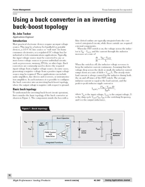
 VVDLPPINOUT INOUT Texas Instruments Incorporated IntegratedFunctio ID: 306392

www.ti.com/aaj4Q 2007industrial telecommunications applications.

Share:

Link:

Embed:

Download Presentation from below link

Download Pdf The PPT/PDF document "16Analog Applications Journal" is the property of its rightful owner. Permission is granted to download and print the materials on this web site for personal, non-commercial use only, and to display it on your personal computer provided you do not modify the materials and that you retain all copyright notices contained in the materials. By downloading content from our website, you accept the terms of this agreement.


Presentation Transcript

16Analog Applications Journal www.ti.com/aaj4Q 2007industrial or telecommunications applications. Typically,such as processors, memory, FPGAs, or other logic. Buck VVDLPPINOUT INOUT Texas Instruments Incorporated IntegratedFunctionsBootCapacitor REF+++– PWMControlGateDrive Figure 1. Buck topology Texas Instruments Incorporated 17Analog Applications Journal polarity, as the output voltage is negative. During operation,/L.plied by energy stored in the output capacitor. When the/L. During the off time,ishthe energy lost by the capacitor during the on time. Sowhen the buck converter is used as a buck-boost converter.component losses neglected. To implement the buck-boostdevice’s V OUTINOUT LPP OUT as in the buck converter. This combined voltageThese values also differ from those of the buck converter,device’s rated output, the available load current is reducedthe average rated current of the high-side switch FET.to-peak AC current, must be below the internal circuit’sFor the inverting buck-boost converter, there are signifi- LavgOUT OUTOUTIN IntegratedFunctions REF+– BootCapacitor ++ PWMControlGateDrive Figure 2. Inverting buck-boost topology Texas Instruments Incorporated 18Analog Applications Journal www.ti.com/aaj4Q 2007To demonstrate some of the performance differencesing buck-boost and buck converters are shown in Figuresfor the inverting buck-boost converter, and fromto ground for the buck converter. The ground referenceconverter. In the buck converter, the average inductorshunted to ground through the output-filter capacitor. The TimeBase=1µs/div Switching-NodeVoltage=10V/div V=50mV/div(AC-coupled) Figure 3. Inverting buck-boost output voltageripple and switching-node voltage TimeBase=1µs/div C2 Switching-NodeVoltage=10V/div V=50mV/div(AC-coupled) Figure 4. Buck output voltage ripple andswitching-node voltage TimeBase=1µs/div SwitchCurrent=1A/div Figure 5. Inverting buck-boost switch current TimeBase=1µs/div SwitchCurrent=1A/div switch off time. For the inverting buck-boost converter,respectively, each with the same load current of 2 A. The Texas Instruments Incorporated 19Analog Applications Journal buck-boost converter, this is not the case; so the averageIn addition to the converter’s input-voltage constraint offor the inverting buck-boost converter as well; however,. At start-up, the output is 0 V; so thefigured as an inverting buck-boost converter. The circuitinput-voltage rating of the device. Finally, the ground ofloadan Acrobat Reader file at www-s.ti.com/sc/techlit/the materials listed below.Document Title1.“The Right-Half-Plane Zero—A Simplified Explanation” . . . . . . . . . . . . . . . . . . . . . . . . . . . . .slup0842.John Tucker, “Using the TPS5430 as an Inverting Buck-Boost Converter,” Application Report . . . . . . . . . . . . . . . . . . . . . . . .slva257power.ti.comwww.ti.com/sc/device/TPS5430 IMPORTANT NOTICE Texas Instruments Incorporated and its subsidiaries (TI) reservestandard warranty. Testing and other quality control techniques areused to the extent TI deems necessary to support this warranty.applications using TI components. To minimize the risksunder the patents or other intellectual property of the third party, or aTexas Instruments products and application solutions: TIWorldwide Technical Support InternetTI Semiconductor Product Information Center Home Pagesupport.ti.comTI Semiconductor KnowledgeBase Home Pagesupport.ti.com/sc/knowledgebase Phone+1(972) 644-5580Fax+1(972) 927-6377 Internet/Emailsupport.ti.com/sc/pic/americas.htmEuropean Free Call00800-ASK-TEXASInternational+49 (0) 8161 80 2121Russian Support+7 (4) 95 98 10 701The European Free Call (Toll Free) number is not active in all countries. If you havetechnical difficulty calling the free call number, please use the international number above.Fax+(49) (0) 8161 80 2045 International+81-3-3344-5317Domestic0120-81-0036Internationalsupport.ti.com/sc/pic/japan.htm Domesticwww.tij.co.jp/picInternational+886-2-23786800DomesticToll-Free NumberToll-Free NumberAustralia1-800-999-084Malaysia1-800-80-3973China800-820-8682New Zealand0800-446-934Hong Kong800-96-5941Philippines1-800-765-7404India+91-80-41381665 (Toll)Singapore800-886-1028Indonesia001-803-8861-1006Taiwan0800-006800Korea080-551-2804Thailand001-800-886-0010Fax+886-2-2378-6808Emailtiasia@ti.comInternetsupport.ti.com/sc/pic/asia.htmti-china@ti.com of similar import. Similarly, such statements herein that describethe company's products, business strategy, outlook, objectives,of operations. We disclaim any intention or obligation to updateTrademarks: Mailing Address: Texas InstrumentsDallas, Texas 75265 © 2007 Texas Instruments Incorporated Telephony Video & Imaging www.ti.com/wireless SLYT