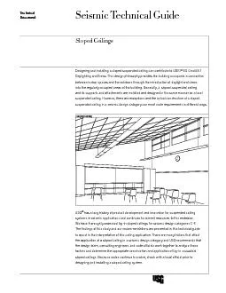
/
Seismic Technical GuideTechnicalSloped Ceilings Seismic Technical GuideTechnicalSloped Ceilings

Seismic Technical GuideTechnicalSloped Ceilings - PDF document

cheryl-pisano
cheryl-pisano . @cheryl-pisano
Follow
438 views
Uploaded On 2015-10-25

Seismic Technical GuideTechnicalSloped Ceilings - PPT Presentation

EQ Credit 81 Daylighting and ViewsThis design philosophy provides the building occupants a connection between indoor spaces and the outdoors through the introduction of daylight and views loped Ce ID: 171553

Credit 8.1 Daylighting

Share:

Link:

Embed:

Download Presentation from below link

Download Pdf The PPT/PDF document "Seismic Technical GuideTechnicalSloped C..." is the property of its rightful owner. Permission is granted to download and print the materials on this web site for personal, non-commercial use only, and to display it on your personal computer provided you do not modify the materials and that you retain all copyright notices contained in the materials. By downloading content from our website, you accept the terms of this agreement.


Presentation Transcript

Seismic Technical GuideTechnicalSloped Ceilings EQ Credit 8.1 Daylighting and Views.This design philosophy provides the building occupants a connection between indoor spaces and the outdoors through the introduction of daylight and views loped Ceilings Hold-down clips should be used for ceilings with slopes At least one hold-down should be used for each panel installed on the perimeter of the higher/top end of the slope.USG V15 and L15 hold-down clips are acceptable for use in sloped installations.The main tees shall run up/down, parallel with the slope.Hanger wires shall be suspended vertically. Struts shall remain vertical and the splay wires installed at max. 45° to the horizontal.Fabricated or locally sourced wall molding can be used to match the angles of the slope.For installations where 7/8-in.� wall molding is desired and the slope is 15°, it is recommended that USG M7 wall molding be installed with the USG adjustable wall molding bracket. For installations utilizing the SB2 adjustable wall molding bracket, the brackets shall be spaced max. 24 in.Lower/bottom end of slope should be installed as a tight side in seismic design categories D, E and F.Higher/top end of slope should be installed as a oating side in seismic design categories D, E and F.The USG MAC2 clip may be used to secure the tee ends to the wall molding and eld modied to match For installations with fabricated molding where the slope is ° theUSG ACM7 seismic clip may be used on For installations with fabricated molding where the slope is ° the USG ACM7 seismic clip may be used &#x 15,;6.9;Ceilings with slopes 25° should be engineered.Sloped Ceilings Sloped Ceilings 3Components Adjustable Wall Molding BracketPanel Hold Down Clip Sloped Ceilings loped Ceilings Seismic Design Category CSeismic Design Category D, E, FMain-tee ClassicationsIntermediate DutyHeavy DutyPerimeter vertical hanger wires not more than 8 in. from wallNot requiredRequired3/4 in. (two adjacent sides)7/8-in. min.2-in. min. without seismic clipPerimeter tee ends tied together at perimetersRequiredRequiredHorizontal restraint (splay wires or rigid bracing) within 2 in. of intersection and splayed 90° apart at 45° angles f�or ceiling areas 1,000 sq. ft.Not requiredRequiredCompression posts (struts) 12 ft. o.c. in both directions, starting 6 ft. from walls f�or ceiling areas 1,000 sq. ft.Not requiredRequiredSeismic separation joint f�or ceiling areas 2,500 sq. ft.Not requiredRequiredThis is only intended as a quick reference. For a complete listing of these requirements please visit usg.com or seismicceilings.com. Because codes continue to evolve, check with a local ofcial prior to designing and installing a suspended ceiling system.When the perimeter closure angle approved for use provides min. 78 in [22 mm] support ledge.Please see ICC-ESR-1222 for more information regarding the alternative wall moldings that may be used with the USG ACM7 seismic clip.USG ACM7 seismic clip satises this requirement per ICC-ESR-1222.Perimeter Treatment Seismic Design Category CSeismic Design Category D, E, Fattachment on all tee ends or 7/8-in. fabricated / locally sourced wall molding with positive attachment on USG M7 wall molding with ACM7 seismic clip or 7/8-in. fabricated / locally sourced wall molding with USG M7 wall molding with ACM7 seismic clip or 7/8-in. fabricated / locally sourced wall molding with SB2 adjustable wall molding bracket with positive attachment on all tee ends or 7/8-in. fabricated / locally sourced wall molding with positive attachment SB2 adjustable wall molding bracket and the USG ACM7 seismic clipSB2 adjustable wall molding bracket and the USG ACM7 seismic clipFabricated / locally sourced wall molding with positive attachment on EngineeredEngineered Requirements Sloped Ceilings Sloped Ceilings 5 SB2 Adjustable Wall Molding BracketPerimeter Treatment The SB2 adjustable wall molding bracket is a convenient way to secure standard wall molding at an angle to accommodate a sloped acoustical ceiling. The brackets can be eld modied to accommodate numerous slopes while utilizing standard wall molding. The SB2 adjustable wall molding bracket eliminates the need for fabricated wall molding and facilitates the use of the USG ACM7 seismic clip in sloped applications. Seismically tested and listed in PEI Evaluation Report, PER-12059. SB2 Adjustable Wall Molding Bracket loped Ceilings Installation Typical Angles Higher/Top End of SlopeAttachment to Wall 1027/8"111/16"13/16"51/4" 15 20 25 27/8"51/4"111/16"13/16" 10 15 20 25 fastener attachment to wall SB2 Adjustable Wall Molding Bracket Sloped Ceilings 7 Additional Wall Molding to Finish Gap 255/16" 1/4" 3/16" 1/8"201510 Visible gap located on Additional wall molding may be applied below the angled wall molding to conceal the gap created by the sloped SB2 Adjustable Wall Molding Bracket loped Ceilings Installation 5/16"1/4"3/16"1/8"25201510 Seismic Applications Angles and gaps with ACM7 Clip gap shown for typical seismic design categories D-F. 3/8 gap is typical for seismic design category C.SB2 Adjustable Wall Molding Bracket 9Construction Generally, sloped suspended ceilings are installed attached at the perimeter or free-oating from the perimeter. AttachedFree-Floating loped Ceilings SeismicNon-Seismic CategoryCategory CCategory D, E, FCategory CCategory D, E, FMain-tee ClassicationsIntermediate or Heavy DutyIntermediate or Heavy DutyIntermediate DutyHeavy DutyIntermediate DutyHeavy Dutywires not more than 8 in. Not requiredNot requiredNot requiredRequired3/4 in. 7/8-in. min.2-in. min. without typically used.typically used.together at perimeters*Not requiredNot requiredRequiredRequiredRequiredRequiredHorizontal restraint (splay wires or rigid bracing) within 2 in. of intersection and splayed 90° apart at min.45° angles for ceiling �areas 1,000 sq. ft.Not requiredNot requiredNot requiredRequiredNot requiredRequired12 ft. o.c. in both directions, starting 6 ft. from walls for �ceiling areas 1,000 sq. ft.Not requiredNot requiredNot requiredRequiredNot requiredRequiredSeismic separation joint for �ceiling areas 2,500 sq. ft.Not requiredNot requiredNot requiredRequiredNot requiredRequiredNot requiredNot requiredfor each panel located at the perimeter of of the slope. At least one installed for each for each panel located at the perimeter of of the slope. At least one installed for each for each panel located for each panel located around the *USG ACM7 seismic clip satises this requirement per ICC-ESR-1222. Construction General Main tees parallel with the slope and hanger wires suspended vertically. main teecross teecross teehanger wirewall Fabricated or locally sourced molding can be used to match the angles locally fabricated locally fabricated The USG MAC2 clip may be used to secure the tee ends and eld modied to match the slope of the tees M7 wall moldingM7 wall molding to match the slope of the tees For installations where the slope is 15° - 25°, it is recommended that USG M7 molding be installed with the USG adjustable wall molding bracket. M7 wall moldingSB2 adjustable wall molding bracketSB2 adjustable wall molding bracketM7 wall moldingceiling slope is 15 - 25 Applications loped Ceilings Lateral Bracing When required, struts are to remain vertical and the splay wires installed at max. 45° to the horizontal. Please refer to SC2497 for more information about struts. horizontal axisYYYZZXXvertical axishorizontal axishorizontal horizontal axisvertical axisvertical axis 4545 or greater main tee main tee slopedmain tee slopedFront ViewSide ViewTop Viewcross teecross tee45 or greaterpost installed verticallystructure post installed structure vertical hanger vertical hanger vertical hanger wire splay wire splay wire cross tee YZXhorizontal axishorizontal axisvertical axis main tee slopedTop View(with splay wires at 45 from horizontal axes)cross post installed vertically vertical hanger wire Applications Seismic Design Categories Lower/bottom end of slope should be installed as a tight side. Higher/top end of slope should be installed as a oating side. For installations where 7/8-in. wall molding is desired and the slope is 15° – 25°, it is recommended that USG M7 molding be installed with the SB2 adjustable wall molding bracket. M7 wall moldingSB2 adjustable wall molding bracketSB2 adjustable wall molding bracketM7 wall molding ceiling slope is 15 - 25 For installations with fabricated molding where the slope is ° the USG ACM7 seismic clip may be used on theof the clip. Note a slight mouse hole or opening may be visible in this application. locally fabricated moldinglocally fabricated moldingUSG ACM7 clip installed with the back flanges on the inside of the wall molding The USG ACM7 seismic clip is not designed to function with wall molding fabricated a�t an angle 105° or ° gap shown for typical seismic design categories D-F. gap is typical for seismic design category C.Applications loped Ceilings For installations with standard wall molding where the slope is 15°, the USG ACM7 seismic clip may be used on the with a fastener through either lower fastener hole on the wing. The USG ACM7 seismic clip is not designed to function with wall molding fabricated a�t an angle 105° or ° USG ACM7 clip installed with the back flanges on the inside of the wall molding For installations with standard wall molding where the slope is 15°, the USG MAC2 clip may be used to secure the tee ends on the lower/bottom end of slope and eld modied to match the slope of the tees. M7 wall moldingM7 wall molding USG ACM7 clip installed with the back flanges on the inside of the wall molding match the slope of the tees For installations with fabricated molding where the slope is 15°, the USG MAC2 clip may be used to secure the tee ends on the lower/bottom end of slope and eld modied to match the slope of the tees. locally fabricated moldinglocally fabricated moldingUSG ACM7 clip installed with the back flanges on the inside of the wall molding match the slope of the tees Attachments MethodsApplications Sloped Ceilings 15 slope  14 Floating / Unattached SideFloating / Unattached SideFloating / Unattached SideFloating / Unattached Side Low EndHigh End Attached Seismic Design Category CSlope  14 slope 15  25 Floating / Unattached Side Floating / Unattached SideFloating / Unattached Side Low EndHigh End Attached Seismic Design Category CSlope 15  14 Category C Category CSeismic Design Categories Sloped Layouts Main Tee Surrounding WallKEY 4 ft. Cross Tee 2 ft. Cross Tee Perimeter TrimStabilizer BarPanel Hold-Down ClipUSG ACM7 Seismic Clip or USG MAC2 Clip USG ACM7 Seismic Clip Main TeeSurrounding Wall KEY 4 ft. Cross Tee2 ft. Cross TeePerimeter TrimStabilizer BarPanel Hold-Down ClipUSG ACM7 Seismic Clip or USG MAC2 Clip USG ACM7 Seismic Clip Main TeeSurrounding WallKEY4 ft. Cross Tee2 ft. Cross Tee Perimeter Trim Stabilizer BarPanel Hold-Down Clip USG ACM7 Seismic Clip or USG MAC2 Clip USG ACM7 Seismic Clip Main Tee Surrounding Wall KEY4 ft. Cross Tee2 ft. Cross TeePerimeter Trim Stabilizer Bar Panel Hold-Down Clip USG ACM7 Seismic Clip USG ACM7 Seismic Clip Main Tee Surrounding WallKEY 4 ft. Cross Tee 2 ft. Cross Tee Perimeter TrimStabilizer BarPanel Hold-Down ClipUSG ACM7 Seismic Clip or USG MAC2 Clip USG ACM7 Seismic Clip Main TeeSurrounding Wall KEY 4 ft. Cross Tee2 ft. Cross TeePerimeter TrimStabilizer BarPanel Hold-Down ClipUSG ACM7 Seismic Clip or USG MAC2 Clip USG ACM7 Seismic Clip Main TeeSurrounding WallKEY4 ft. Cross Tee2 ft. Cross Tee Perimeter Trim Stabilizer BarPanel Hold-Down Clip USG ACM7 Seismic Clip or USG MAC2 Clip USG ACM7 Seismic Clip Main Tee Surrounding Wall KEY4 ft. Cross Tee2 ft. Cross TeePerimeter Trim Stabilizer Bar Panel Hold-Down Clip USG ACM7 Seismic Clip USG ACM7 Seismic Clip Tight Fixed Sideslope  14Floating / Unattached SideTight Fixed SideFloating / Unattached SideLow EndHigh End Attached Seismic Design Category D, E, FSlope  14 slope 15  25Floating / Unattached SideFloating / Unattached Side Tight Fixed SideTight Fixed SideLow EndHigh End Attached Seismic Design Category D, E, FSlope 15  25 Category D, E, F Category D, E, FSloped LayoutsSeismic Design Categories loped Ceilings Sloped Ceilings 17 slope 15  25 Low EndHigh End Free Floating Seismic Design Category C, D, E, FSlope 15  25 Main Tee Surrounding WallKEY 4 ft. Cross Tee 2 ft. Cross Tee Perimeter TrimStabilizer BarPanel Hold-Down ClipUSG ACM7 Seismic Clip or USG MAC2 Clip USG ACM7 Seismic Clip Main TeeSurrounding Wall KEY 4 ft. Cross Tee2 ft. Cross TeePerimeter TrimStabilizer BarPanel Hold-Down ClipUSG ACM7 Seismic Clip or USG MAC2 Clip USG ACM7 Seismic Clip Main TeeSurrounding WallKEY4 ft. Cross Tee2 ft. Cross Tee Perimeter Trim Stabilizer BarPanel Hold-Down Clip USG ACM7 Seismic Clip or USG MAC2 Clip USG ACM7 Seismic Clip Main Tee Surrounding Wall KEY4 ft. Cross Tee2 ft. Cross TeePerimeter Trim Stabilizer Bar Panel Hold-Down Clip USG ACM7 Seismic Clip USG ACM7 Seismic Clip Category C, D, E, F Free Floating Sloped LayoutsSeismic Design Categories SC2508/rev. 6-13© 2013, USG Interiors, LLCManufactured byUSG Interiors, LLC550 West Adams StreetChicago, IL 60661CAUTIONAvoid bending the bracket back and forth too many times which will cause metal fatigue See usg.com for the most up-to-date product information.with ASTM C636, ASTM E580, CISCA, and standard industry practices. the installation of suspended ceilings to level applications and conditions. Many jurisdictions accept the installation of sloped suspended ceilings, however, sloped ceiling installations. The information presented knowledge at the date of issuance. Because codes continue to evolve, check with system. Other restrictions and exemptions may apply. This is only intended as a quick for design professionals, to promote more uniform criteria for plan review and jobsite inspection of projects. This STG indicates an accept-able method for achieving compliance with applicable codes and regulations, although other methods proposed by design professionals may be ICC Evaluation Service, Inc., manufactured by USG Interiors, Inc., have been reviewed and are approved by listing in ICC-ES Evaluation Report 1222. Evaluation Reports are subject to reexamination, revision and possible cancellation. Please usg.com for current reports.L.A. Research Report DONN manufactured by USG Interiors, Inc., have been reviewed and are approved by listing in the following L.A. Research Report number: 25764.Inc. Evaluation Report Seismically tested and listed in PEI Evaluation Report, PER-12059. The following are trademarks of USG nteriors, Inc. or a related company:USG, USG in stylized letters. LEED is a registered trademark of U.S. Green sustainableceilings.comWe shall not be liable for damages, directly or indirectly sustained, nor for any loss caused by application of these for other than the intended use. Our liability is expressly limited goods. Any claim shall be (30) days from date it was or reasonably should have been hygiene practices during installation. Wear appropriate personal protective equipment. Read MSDS and literature before specication and installation. denes Seismic Design Categories A, B, C, D, E, and F. www.iccsafe.orgAmerican Society of Civil Engineers/Structural Engineer Institute (ASCE/SEI)www.asce.orgRecommendations for Direct-hung Acoustical Tile and Lay-in Panel Ceilings (Zones 0-2)CISCA Ceilings & Interior Systems Construction Association (CISCA)www.cisca.orgfor Acoustical TIle and Lay-in Panels in Areas Subject to Earthquate Ground Motions.ASTM International (formerly American Society for Testing and Materials) www.astm.orgSeismic Technical Guides Association (CISCA)