/
THE EXPERT IN LEVEL AND FLOW THE EXPERT IN LEVEL AND FLOW

THE EXPERT IN LEVEL AND FLOW - PDF document

cheryl-pisano
cheryl-pisano . @cheryl-pisano
Follow
384 views
Uploaded On 2016-03-15

THE EXPERT IN LEVEL AND FLOW - PPT Presentation

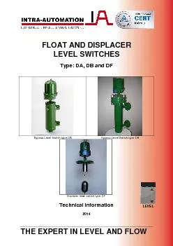
LEVEL FLOAT AND DISPLACER LEVEL SWITCHES Type DA DB and DF Bypass Level Switch type DA Bypass Level Switch type DB Displacer level switch type DF Technical Information Level Switches type DA ID: 257182

LEVEL FLOAT AND DISPLACER LEVEL

Share:

Link:

Embed:

Download Presentation from below link

Download Pdf The PPT/PDF document "THE EXPERT IN LEVEL AND FLOW" is the property of its rightful owner. Permission is granted to download and print the materials on this web site for personal, non-commercial use only, and to display it on your personal computer provided you do not modify the materials and that you retain all copyright notices contained in the materials. By downloading content from our website, you accept the terms of this agreement.


Presentation Transcript

THE EXPERT IN LEVEL AND FLOW LEVEL FLOAT AND DISPLACER LEVEL SWITCHES Type: DA, DB and DF Bypass Level Switch type DA Bypass Level Switch type DB Displacer level switch type DF Technical Information Level Switches type: DA, DB and DF Technical Information Intra-Automation - 2 - Intra-Automation GmbH Technical Information © 2014 Intra-Automation GmbH Printing errors and technical changes reserved. For all comments regarding this brochure, please contact info@intra-automation.de Intra-Automation Technical Information Level Switches type: DA, DB and DF - 3 - Chapt. Content Page 1 Level Switches series DA, DB (Float operated) 4 1.1 Functional principle 4 1.2 Design 4 1.3 Applications 5 1.4 Technical data 5 1.5 Order code for DA / DB 6 2 Level Switches series DF (Displacer operated) 8 2.1 Functional principle 8 2.2 Design 8 2.3 Special versions 10 2.4 Order code for DF standard design 11 2.5 Order code for DF special design 13 Level Switches type: DA, DB and DF Technical Information Intra-Automation - 4 - Level Switches series DA, DB (Float operated) Functional principle The level of liquid present in a vessel is checked by the float being inside the main body, the chamber, of the Level Switch. When level rises up to the preset height, the float makes the output device trip (trip on rise); when level comes down again and exceeds the preset height, the float makes the output device come back to the initial position (reset on fall); between the set and reset heights there is always a gap, named differential : see below. The inverse function is available too : Trip on fall and Reset on rise. The output device can be electric or pneumatic, is snap action and is placed in the housing. Differently from DA, the type DB is provided with inspection flanges, allowing to open the instrument and to clean it from possible residues of the liquid under control. The level switches meet the PED and ATEX standards. Design Side-Side mounting Fig. A Side-Bottom mounting Fig B Sleeve mounting (thread or welded) Fig C/D Type DA Type DB Dimensions: M (mm) H (mm) L (mm) DA, DB DA DA DB DA DA, DB DA pressure rating (ANSI) 150…600 1500…2500 150…600 150…600 1500…2500 150…600 1500…2500 Fig. A 178 178 660 710 750 195 220 Fig. B 350 400 730 780 800 195 220 Fig. C 178 178 660 710 660 90 115 Fig. D 250 300 630 680 680 90 115 (Special versions on request) Intra-Automation Technical Information Level Switches type: DA, DB and DF - 5 - Applications Alarm for Max and Min level, control of pumps on vessels including simple water or chemical corrosive or toxic liquids, under pressures and temperatures also very high or very low; for liquids with specific gravity from 500kg/m³ up. Technical data 1.4.1 Body Materials : Carbon steel ASTM A106B, stainless AISI 304, or AISI 316. Size : Øouter 4” (114,3mm), different thickness as per ASME standards. Rating : ANSI 150, 300, 600, 1500, 2500 psi. Bottom : The Side-Side Switches have drain hole ¾” NPT-F threaded (upon request, ½” NPT-F or 1” NPT-F), with or without accessories (plugs, valves, etc). Inspection flanges : Øouter 3” in the ratings ANSI 150 to 600 psi (face RF) out. 2½” in the ratings ANSI 1500 to 2500 psi (face RJ). 1.4.2 Connections to vessel Materials : Carbon steel ASTM A105N, stainless AISI 304, or AISI 316. Flanges (ANSI) : 150 to 2500 psi, Ø 1 to 2” Flanges (DIN) : PN 10 to 100, DN 25 to 100 Sleeves : Threaded or socked welding Mounting : Side-Side or Side-Bottom. C/C-distance M: : As per table page 4, other distances on request 1.4.3 Housing Aluminium cast, in electric or pneumatic version: With 1 or 2 microswitches SPDT with simultaneous action size : Ø155×200mm, flame-proof EEx dc IIC T6; 1 hole for electric connection : ¾ ” NPT-F threaded (or ½” NPT-F) housing-holder height : - 80mm for temperatures of –20/+180°C - 145mm for higher or lower temperatures. With 1 pneumatic valve On/Off/Vent; Ø125×180mm, water-proof; 3 holes for air connection ¼” NPT-F : inlet, outlet and vent; housing-holder height : - 70mm for temperatures of –20/+180°C - 130mm for higher or lower temperatures. 1.4.4 Differential The Switch trips when level reaches the X height and resets when comes back to Y height (or on the contrary), as per the side sketch. Usually the X point is fixed at 70mm below the top connection, and between X and Y there is a differential of about 30÷65mm (it changes on basis of the specific gravity of liquids); but, upon request, such heights and differentials can be made different too. 1.4.5 Outer finish Switches in carbon steel have the standard painting so realized : first coat in epoxy resin, and outer coat in green polyurethane resin; suitable for corrosive marine environments and tropical climates. Switches in stainless steel are polished and left bare. Level Switches type: DA, DB and DF Technical Information Intra-Automation - 6 - Order code for DA / DB Code Description 1. Type of level switch DA- Level switch without inspection flanges DB- Level switch with inspection flanges 2. Mounting Side-Side Side-Bottom 3. Mounting parts Flanges DIN F Flanges ANSI with RF-face Flanges ANSI with RJ (Ring Joint)-face N Sleeves, female threaded, NPT-F Sleeves, male threaded, NPT-M Sleeves, socket welded 4. Pressure rating ANSI 150 lbs ANSI 300 lbs ANSI 600 lbs ANSI 1500 lbs ANSI 2500 lbs PN10 PN16 PN25 PN40 PN64 PN100 5. Connection size 1” 1 ½” 2” 6. Center to center distance Please replace by the c to c distance in mm 7. Body and connection material CCS 304SS 316SS 8. Drain Side-bottom no drain possible ½”NPT-F ¾”NPT-F 1”NPT-F with drain, no accessory with drain, plugged (mat. as body) with drain, with valve with drain, with valve and plug - - - - Intra-Automation Technical Information Level Switches type: DA, DB and DF - 7 - Coding (Continuation) - - - - 9. Housing Electric of pneumatic output 6A/24VDC, silver contact /5A/30VDC, silver contact 1mA/5VDC (min); 1A/125VDC (max); gold contact sealed in inert gas, /1,5A/30VDC, silver contact sealed in inert gas, 1mA/5VDC (min); 0,5A/30VDC (max); gold contact 1 pneumatic valve ON-OFF, opens air when level rises, with 2 manometers 1 pneumatic valve ON-OFF, closes air when level rises, with 2 manometers Please replace by the number of switches (SPDT with simultaneous action) Hole for electric connection ½”NPT-F ¾”NPT-F Housing holder Standard: -20/+180°C High temp.: +181/+450°C with fins Low temp.: -21/-60°C without fins - - - - Standard options printed in BOLD letters. Additionally to the coding, the following information is necessarily needed: Fluid upper: Density: upper: kg/m³ lower lower: kg/m³ Temperature Min.: °COperating: °CMax.: °C Pressure Min.: bar*Operating: bar*Max.: bar* *for easy converting: 15 bar ~ 15 atm ~ 15 kg/cm² ~ 15 kPa ~ 15 MPa Footnotes: The inspection flanges on DB would be out of acceptable proportions in comparison with chamber, and so for such high pressures we suggest to adopt DA. Micro A : also 6A resistive – 250Vac; temperatures of : –25/+85°C. Micro B : also 15A resistive – 3A inductive – 250Vac; temperatures of : -25/+80°C. Micro Q : also 1A – 125Vac, but is recommended for very low electric loads (e.g. insulating barriers with few mA and V); temperatures of : –55/+85°C. Micro R : also 1A resistive – 0,8A inductive – 220Vac; temperatures of : -55/+150°C. Micro Z : recommended for very low electric loads (e.g. insulating barriers with few mA and V); temperatures of : -55/+150°C. Level Switches type: DA, DB and DF Technical Information Intra-Automation - 8 - Level Switches series DF (Displacer operated) Functional principle The level of the liquid present in a vessel is checked by one or more displacers (i.e. floats correctly ballasted) hung on a metallic rope. When level rises up to the preset height, the displacer makes the output device trip (trip on rise); when level comes down again and exceeds the preset point, the displacer makes the output device come back to the initial position (rest on fall); between the trip and reset points there is always a gap, named differential : see below. The inverse function is available too : Trip on fall and Reset on rise. The output device can be electric or pneumatic, is snap action and is placed in the housing. All of them are mounted on top vessel. Several types of Switches are available, with some elements in common. Body and flange in the ratings ANSI 150, 300, 600psi, in carbon steel ASTM A106B (body) and ASTM 105N (flange), stainless AISI 304, or stainless AISI 316. Flange : ANSI or UNI/DIN standards Displacer and rope (L=1÷10m) in stainless AISI 316. The displacer can be fixed on the rope at the desired height, decided by the user himself. For liquids with specific gravity from 500kg/m³ up. Housing and housing-holder : as described below 110 Outer finish : green, for marine and tropical climates, The Switches meet the PED and ATEX standard Design DF1 – It is provided with 1 displacer and 1 output, electric or pneumatic. The output trips when liquid rises (or falls) up to displacer and resets when falls (or rises) of 65 ±15mm (differential not changeable). Output : - electric (1 or 2 micro switches SPDT with simultaneous action : within Ø155×200mm housing); - pneumatic (1 valve ON-OFF, in Ø125×180mm housing). Use : Alarm for Max or Min level, control of loading pump, etc. DF2A – It is provided with 2 displacers and 1 output, electric or pneumatic. The output trips when liquid rises up to the displacer A, and resets when falls up to the displacer B (or on the contrary). The differential can be decided by the same installer : he will fix the displacer A at the trip height, and B at the reset height; in this way the gap between the two displacers corresponds to the wished differential. The minimum differential is 160mm, with the 2 blocks placed under B. Output : - electric (1 or 2 micros SPDT with simultaneous action : in Ø155×200mm housing); - pneumatic (1 valve ON-OFF, in Ø125×180mm housing). Use : Loading of vessel, to stop a loading pump when level rises up to the displacer A, and to start it again when level falls to the displacer B. DF2B – It is provided with 2 displacers and 2 electric outputs. • The output 1 is activated by displacer A placed at L, while the output 2 is activated by displacer B placed at L. The two trips are independent and depend only on the heights at which the displacers are fixed. Each of them resets with differential of 65 ±15mm. DF2B operates as if it were composed by two DF1. • Each output : 1 or 2 micros SPDT with simultaneous action : within Ø155×200mm housing. • Use: Alarm for Max or Min level. It operates as composed by two DF1. DF3 : They are provided with 3 displacers. and various electric outputs (each output has 1 or 2 micros SPDT with simultaneous action)DF3A – The output 1 is activated by the displacer A placed at L(can be used as Max level alarm); the output 2 is activated by the displacer B placed at L(trip) and by the displacer C placed at L(reset). It can be used to control the loading/unloading pump. In Ø155×200mm housing. It operates as if it were composed by one DF1 + one DF2A DF3B – The output 1 is activated by displacers A placed at L(trip) and B placed at L(reset), and can be used to load/unload a vessel. The output 2 is activated by displacer C placed at L, and can be used as Min level alarm. In Ø155×200mm housing. It operates as if it were composed by a DF2A + a DF1. Intra-Automation Technical Information Level Switches type: DA, DB and DF - 9 - DF3C – It is provided with 3 displacers and 3 indipendent electric outputs. Within Ø155×250mm housing. It operates as if it were composed by three DF1. Level Switches type: DA, DB and DF Technical Information Intra-Automation - 10 - Special versions DF1 for floating cover, in TG version When switches are mounted on vessels in which the liquid is protected by a floating cover, displacer is replaced by a solid body with similar weight as displacer’s. When body is lifted by floating cover, it makes output device trip; the output device can be electric or pneumatic, and is placed within housing. APPLICATIONS. Trip for High or Low level, with the same performances as DF1 type. DF1, DF2A-DF2B, DF3A-DF3B-DF3C with damping tube, in TC version When switches are mounted on vessels containing turbulent liquids, We recommend to protect displacers within a damping tube, to avoid untimely trips. Usually such a tube is procured and mounted by the same vessel installer, or, upon request, can be supplied by Domizi Snc already assembled on the Switch. APPLICATIONS. Trip for High or Low level, pump On/Off turning, as for all the DF types. DF1, DF2A-DF2B, DF3A-DF3B-DF3C in DB version When a Switch is mounted on a side of vessels and shall carry out performances being impossibile with DB Switch (e.g. pump On-Off turning with very wide differentials), We propose to use a DF Switch included within a DB body. In this way you get an instrument with performances being typical of DF and with mechanical look of DB, both as body and as connection/inspection flanges. APPLICATIONS. Trip of High or Low level, pump On/Off turning, as for all the DF types. Intra-Automation Technical Information Level Switches type: DA, DB and DF - 11 - Order code for DF standard design Code Description 1. Type of level switch DF1 Level switch with one displacer DF2A Level switch with two displacers DF2B Level switch with two displacers DF3A Level switch with three displacers DF3B Level switch with three displacers DF3C Level switch with three displacers 2. Vessel connection flange Flange acc. DIN Flange acc. ANSI with RF face Flange acc. ANSI with RJ (ring joint) face 2.1 Pressure rating ANSI 150 lbs ANSI 300 lbs ANSI 600 lbs PN10 PN16 PN25 PN40 2.2 Flange size 3” [with displacer Ø76 x 220 mm] H4” [with displacer Ø90 x 150 mm] DN80 [with displacer Ø76 x 220 mm] DN100 [with displacer Ø90 x 150 mm] 3. Material body and flange CS 304SS 316SS 4. Housing 4.1 Electric or pneumatic output 6A/24VDC, silver contact /5A/30VDC, silver contact 1mA/5VDC (min); 1A/125VDC (max); gold contact sealed in inert gas, 3A/1,5A/30VDC, silver contact sealed in inert gas, 1mA/5VDC (min); 0,5A/30VDC (max); gold contact 1 pneumatic valve ON-OFF, opens air when level rises, with 2 manometers 1 pneumatic valve ON-OFF, closes air when level rises, with 2 manometers Please replace by the number of switches 4.2 Hole for electric connection ½”NPT-F ¾”NPT-F 4.3 Housing holder Standard: -20/+180°C High temp.: +181/+450°C with fins Low temp.: -21/-60°C without fins - - Level Switches type: DA, DB and DF Technical Information Intra-Automation - 12 - Coding (Continuation) - - 5. Rope length: 1 m 2 m 3 m 4 m 5 m 6 m 7 m 8 m 9 m 10 m - - - Standard options printed in BOLD letters. Additionally to the coding, the following information is necessarily needed: Fluid upper: Density: upper: kg/m³ lower lower: kg/m³ Temperature Min.: °COperating: °CMax.: °C Pressure Min.: bar*Operating: bar*Max.: bar* *for easy converting: 15 bar ~ 15 atm ~ 15 kg/cm² ~ 15 kPa ~ 15 MPa Footnotes: Micro A : also 6A resistive – 250Vac; temperatures of : –25/+85°C. Micro B : also 15A resistive – 3A inductive – 250Vac; temperatures of : -25/+80°C. Micro Q : also 1A – 125Vac, but is recommended for very low electric loads (e.g. insulating barriers with few mA and V); temperatures of : –55/+85°C. Micro R : also 1A resistive – 0,8A inductive – 220Vac; temperatures of : -55/+150°C. Micro Z : recommended for very low electric loads (e.g. insulating barriers with few mA and V); temperatures of : -55/+150°C. Intra-Automation Technical Information Level Switches type: DA, DB and DF - 13 - Order code for DF special design Code Description 1. Type of level switch DF1 Level switch with one displacer DF2A Level switch with two displacers DF2B Level switch with two displacers DF3A Level switch with three displacers DF3B Level switch with three displacers DF3C Level switch with three displacers 2. Special version Switch for floating cover Switch with damping tube Switch DF in the body of DB (see herein after) 3.1 Vessel connection flange (Designs TG and TC) Flange acc. DIN Flange acc. ANSI, flange face RF Flange acc. ANSI, flange face RJ (ring joint) 3.2 Pressure rating ANSI 150 lbs ANSI 300 lbs ANSI 600 lbs PN10 PN16 PN25 PN40 3.3 Flange size 3” [recommended for DB-design] H 4” DN80 DN100 4. Material body and flange CCS 304SS 316SS 5. Housing 5.1 Electric or pneumatic outputs 6A/24VDC, silver contact /5A/30VDC, silver contact 1mA/5VDC (min); 1A/125VDC (max); gold contact sealed in inert gas, /1,5A/30VDC, silver contact sealed in inert gas, 1mA/5VDC (min); 0,5A/30VDC (max); gold contact 1 pneumatic valve ON-OFF, opens air when level rises, with 2 manometers 1 pneumatic valve ON-OFF, closes air when level rises, with 2 manometers Please replace by the number of switches - - - Level Switches type: DA, DB and DF Technical Information Intra-Automation - 14 - Coding (Continuation) - - - 5.2 Hole for electric connection ½”NPT-F ¾”NPT-F 5.3 Housing-holder Standard: -20/+180°C High temp.: +181/+450°C with fins Low temp.: -21/-60°C without fins 6. Rope length 1 m 2 m 3 m 4 m 5 m 6 m 7 m 8 m 9 m 10 m - - - * The coding for TG and TC ends here, for version DB, please add the below coding. Additional coding for DB-design Code Description 7. Mounting L Side-Side Side-Bottom 7.1 Tank connection of bypass vessel (mounting parts) Flanges DIN F Flanges ANSI with RF-face Flanges ANSI with RJ (Ring Joint)-face N Sleeves, female threaded, NPT-F Sleeves, male threaded, NPT-M Sleeves, socket welded 7.2 Size mounting parts 1” 1 ½” 2” DN25 DN40 DN50 8. Center to center distance of tank connections Please replace by the c to c distance in mm 9. Drain - - Standard options printed in BOLD letters. Intra-Automation Technical Information Level Switches type: DA, DB and DF - 15 - Coding (Continuation) Additionally to the coding, the following information is necessarily needed: Fluid upper: Density: upper: kg/m³ lower lower: kg/m³ Temperature Min.: °COperating: °CMax.: °C Pressure Min.: bar*Operating: bar*Max.: bar* *for easy converting: 15 bar ~ 15 atm ~ 15 kg/cm² ~ 15 kPa ~ 15 MPa Footnotes: Micro A : also 6A resistive – 250Vac; temperatures of : –25/+85°C. Micro B : also 15A resistive – 3A inductive – 250Vac; temperatures of : -25/+80°C. Micro Q : also 1A – 125Vac, but is recommended for very low electric loads (e.g. insulating barriers with few mA and V); temperatures of : –55/+85°C. Micro R : also 1A resistive – 0,8A inductive – 220Vac; temperatures of : -55/+150°C. Micro Z : recommended for very low electric loads (e.g. insulating barriers with few mA and V); temperatures of : -55/+150°C. Level Switches type: DA, DB and DF Technical Information Intra-Automation - 16 - Besides the products covered by this brochure, Intra-Automation GmbH also manufactures other high-quality and high precision instruments for industrial measurement tasks. For more information, please contact us (contact details on the backside of this brochure). Flow measurement on the differential pressure principle: Itabar-Flow-Sensor (pitot tube) Orifice Assembly Div. types of orifice flow measurements Cone Flow Meter Flow Nozzle Venturi Tube Wedge Flow Meter Intra-Automation Technical Information Level Switches type: DA, DB and DF - 17 - Bypass level measurement ITA mag. level gauge ITA-TG Transparent level gauge ITA-RG Reflex level gauge ITA-GG Tubular level gauge The Intra-Automation product line is also completed by all kinds of electronic accessories like switches and transmitters. Also, it is changing from time to time in order to get completed. To be up-to-date, please frequently visit our homepage www.intra-automation.com for your information. Level Switches type: DA, DB and DF Technical Information Intra-Automation - 18 - International Headquarters: Sales Office for the BENELUX: Intra-Automation GmbH B.V. Intra-Automation HTP Otto-Hahn-Str. 20 PO Box 10 41515 Grevenbroich 4730 AA Oudenbosch GERMANY THE NETHERLANDS +49 – (0) 21 81 / 7 56 65-0 +31 – (0)165 – 32 22 01 +49 – (0) 21 81 / 6 44 92 +31 – (0)165 – 32 29 70 info@intra-automation.de info@intra-automation.nl www.intra-automation.com