/
Booster Beam Notching  PMG Meeting Booster Beam Notching  PMG Meeting

Booster Beam Notching PMG Meeting - PowerPoint Presentation

cleverfan
cleverfan . @cleverfan
Follow
343 views
Uploaded On 2020-11-06

Booster Beam Notching PMG Meeting - PPT Presentation

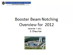
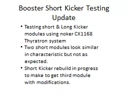
Salah Chaurize August 21 2013 Notching History Notching is controlled removal of selected proton bunches to facilitate a gap in the beam This gap allows the Booster extraction kickers magnetic fields to reach full value to allow extraction of the remaining bunches ID: 816659

long beam short kicker beam long kicker short notching pulser aperture notched absorber notch booster mev l13 spool kickers

Share:

Link:

Embed:

Download Presentation from below link

Download The PPT/PDF document "Booster Beam Notching PMG Meeting" is the property of its rightful owner. Permission is granted to download and print the materials on this web site for personal, non-commercial use only, and to display it on your personal computer provided you do not modify the materials and that you retain all copyright notices contained in the materials. By downloading content from our website, you accept the terms of this agreement.


Presentation Transcript

Slide1

Booster Beam Notching PMG Meeting

Salah Chaurize

August 21, 2013

Slide2

Notching HistoryNotching is controlled removal of selected proton bunches to facilitate a gap in the beam.This gap allows the Booster

extraction kickers magnetic fields to reach full value to allow extraction of the remaining bunches.Without the gap or “notch” in the beam, the extraction kickers would displace these bunches in a non-controlled fashion causing losses in the extraction regionIn the past “notching” was less critical due to lower beam intensities and lower beam duty cycles. Losses were tolerable.

Slide3

Longitudinal distribution of

3 removing (red),

circulating (green)

and

survival at notching (blue)

bunches, and long (1.08m) and short (0.54m) notchers waveform at Long-13, and 1.08-m notcher waveform for Long-05 straight section.

December, 2011 A.Drozhdin

Slide4

The Notch/Gap

3 Bucket Notch Width

non-cogged Cycle Notch @ 400MeVCogged Cycle Notch

@ ~700MeV

Extraction Loss

Gap

Slide5

Booster Kicker Notching PlansPhase ICreate a Horizontal Notch scheme to deposit beam at L13 using existing Notching magnet systems.

Reduce losses to sensitive locations such as gradient magnets and RF cavities.Phase I is complete.Phase IIImprove notch kicker rise time to allow cleaner gap clearing and emmittance

growth of bunches adjacent to the cleared bunches.Build new short kickers and fast pulser to drive faster notch producing system.Magnets building in progress. Kicker power system building underway. Phase II is in progress.

Slide6

Notching Pre-Shutdown 2012

A 3 bucket gap is created using two kickers located at Long 5 and Long 12Notcher – A High Voltage(55kV) Kicker at Long 5Noker - Lower Voltage Kicker (20-40 kV) at Long 12Used to clean out remnant n

otched beam in bucketsAt ~700 MeV due to Cogging operations.Beam is kicked vertically into Gradient Magnet dipoles at L5 and L12. Some notched beam reaches the collimator region at Long 6 and beam pipe mask at Long 13. This is not optimal Non-cogged notched cycles occurs at ~400 MeV.Cogged notch cycles occurs at ~700 MeV.

Slide7

Notching Magnets at Long 5 and Long 12 Pre-Shutdown 2012

Notcher

Hor.

Pinger

De-commissioned

Horz. PingerVer. PingerNokerMKS04Beam directionL12 Pre-2012 Shutdown

L5 Pre-2012 ShutdownBeam direction

Slide8

December, 2011 I.Tropin

Residual dose profiles, vertical cross section (30 days irradiation/1day cooling,

mSv

/

hr

).

Vertical

notcher

Notching at Long 5 Pre-shutdown

Slide9

Booster Kicker Notching PlansPhase ICreate a dedicated region to deposited 3 bunches of beam to produce a extraction kicker rise time gap.

Use current CX1168 thyratrons and PS systems to drive 3 kickers that kick Horizontally rather than vertically. We implemented a three kicker system to go into Long 12 and Long 13 as the absorber regions.

This first phase is completed. Notched beam has been achieved with this new horizontal configuration. Further orbit tuning and timing adjustments will continue as we commission MI beam.

Slide10

Horizontal position of 3-σ circulating beam and removed beam at notching for magnetic field of

two horizontal notchers of B=67Gauss at 400 MeV (top)

and

two notchers of B=72.5Gauss plus one notcher of B=35.2Gauss at 700 MeV (bottom).

Three horizontal notchers at Booster Long-12

with beam dump at Long-13 straight section.

August, 2011

A.Drozhdin

Slide11

Three

notchers

with field of B=62 Gauss.

The aperture of Short-12 straight section should be increased to R>86mm to eliminate losses.

This can be done by

displacement

of R66.5mm

aperture

(without BPM) by dX=20 mm. [46.5-86.5]mm

Y

Short-12

dX=70mm

400MeV

Circulating beam

3

σ

(

ε

=18

π

)

Dump-13

X

Red – 30

π

, green - 18

π

August, 2011

A.Drozhdin

Slide12

Long-13:

Loss Simulations

December, 2011 I.Tropin

Side view

Top view

Slide13

Slide14

Reason to redesign S12 Spool piece

Need to kick beam horizontally at L12 to create a notch in the beam.Horizontal aperture is current 4.5 in at S12

Maximum aperture through Booster Short Corrector is about 5 in. Current aperture restriction at S12 is BPM plates and upstream and down stream bellows which are all 4.5in.

Slide15

Reason to redesign S12 Spool piece

New Extra Wide aperture BPM will give us 5 in aperture with new spool.New spool would use original spool design without the standard BPM components inside and larger aperture spool bellows

Slide16

Extra Wide Aperture BPM

Slide17

Short 12 Corrector Spool Upgrade

New 5” Aperture Spool

Standard aperture 4.5 Inch

New Extra wide BPMStandard BPM inside

Slide18

Notching Post ShutdownPhase I

A 3 bucket gap is created using three Long kickers located at Long 12

3 Notcher – High Voltage(46-54kV) Kickers at Long 12Notcher PS converted to NOKA PSNoker PS converted to NOKB PSBuilt/Commissioned new NOKC PS mostly with parts on hand.Beam is kicked Horizontally into new absorber at Long 13 Extra Wide Aperture BPM and Short Corrector Spool needed to allow kicked beam horizontal displacement before reaching absorber.

Non-cogged notched cycles occurs at ~400 MeV.(unchanged)Cogged notch cycles occurs at ~700 MeV.(Unchanged)

Slide19

L12

Post Shutdown

NOKCMKS04

NOKBNOKA

Slide20

12-13 sections of Booster tunnel.

Long-13

Long-12

Kick

at L12 to Aisle.

Slide21

Long 13 Notched beam absorber

Beam direction

Before

After

Slide22

Long 13

Beam direction

Slide23

Long 13 Actual new absorber

Slide24

Current Configuration

In East Gallery

NOKA

NOKB

NOKC

Slide25

Current Configuration In East Gallery

NIM Gate Modules Altera Based

CAMAC Controls and Ramp Cards

LeCroy

Delay modules & CAMAC Trigger

Slide26

Notching turned On and Off

Extraction loss monitor

Notching off

Notching on

Beam Charge

Slide27

400 MeV Notched beamAbsorber in operational position

Slide28

400 MeV Notched beam

Absorber Retracted

Slide29

700 MeV Notched beam

Currently

Slide30

Preliminary Results and Commissioning

Slide31

Phase IICurrent BKED (Long) design kicker have a rise time of about 35ns Short BKEF kicker modules are about half as long. They will produce a rise time of about 25ns.

The voltage propagation time through the short kicker is cut from 20ns to 10ns due to half length.Two short kickers will rise faster with appropriate pulser to reach a desired flatop value.

We will use a ANU style pulser using a CX2610 hydrogen thyratron rather than the existing CX1168 tube. This new pulser we gain us about 8-15ns of rise time.One Pulser can drive 4 magnets, possibly 6.

Slide32

Phase IIC. Jensen and J. Biggs along with EE support group is currently working on acquiring and building an ANU style pulser

. Pulser components will be built through out 2013.We hope to have one pulser operating in a test configuration by the end of 2013.We will try to convert one long kicker to a pair of 2 short kickers as soon as feasible(2013/14)

Slide33

C. Jensen

Slide34

New Short kicker PS RackFront/Back viewEE Support currently building System

Slide35

New Pulser for Short BKEE/BKEF Kicker Example(ANU Pulser Test Unit)

Slide36

1Long Kicker BKED Series

2 Short Kicker BKEE Series

Slide37

ConclusionHorizontal Beam notching is working.

Estimated notched beam power max is about 250watts which is half the budgeted power loss for Booster. The New L13 notched beam Absorber gives us 50% more head room on lost beam power. This helps towards future 15Hz. Operations

Phase II should give us further improvements towards 15Hz. Operations.

Slide38

Thanks to:-L13 Notched Beam Absorber Assembly-

PPD Experiment Fabrication- L13 Absorber Build and AssemblyD.Erickson, J. Judd, W. Blaszynski, W. Gatfield

V. Sidorov - L13 Absorber Mechanical DesignAPC Energy Deposition Simulations by- N.Mokhov, I. Tropin, S.Drozhdin M. Coburn L13 Absorber Motion Controls

-L12, S12, L13 Upgrade Support-Mechanical Support/ Instrumentation Groups – L13/S12 BPM and CorrectorR. Reily, B. Ogert, J. Kubinski

, J.

Briney

,

D. Wallace, J. FitzgeraldControls Group CAMAC modulesBooster Techs - Power supply and load reconfiguration New timing module build and support electronics R. Mraz, T. Boes, D. DickOperations - Database work , O. Marshall, R. JonesAMG-L12, S12,L13 alignmentRadiation Safety – Joel FulghamConsultation – J. Lackey, B. PellicoMachine Shop, Welding ShopMany More I missed

Slide39

END

Slide40

Reserve Slides

Slide41

Looking upstream towards L13

Before

After

Slide42

Short Kicker/ Power Supply EffortPurpose of short kicker is to reduce kicker magnet rise/fill time.We can improve rise time of magnet field from current ~32nsec to about 25nsec.

This will improve beam bunch removal with reduced disturbance of bunches intended for extraction.

Slide43

New Short Kicker Pulser Control and PS racks location. East Booster Gallery

Slide44

BKEE02(Short Module)Voltage ~40kV

Slide45

BKED012(Long Module)Voltage ~40kV

Slide46

BKEE001

Short

42KV

NokerBKED012Long42KV

Noker

Channel 1 V in

Channel 2

VoutChannel 3 Load I

Slide47

Preliminary finding is a 8-15 ns difference between

ANU

pulser and Operational Booster pulser(Slower)Testing by Jensen, Chaurize