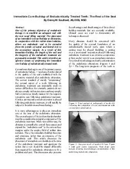
/
Abstract One of the primary objectives of endodontic therapy is to establish an adequate Abstract One of the primary objectives of endodontic therapy is to establish an adequate

Abstract One of the primary objectives of endodontic therapy is to establish an adequate - PDF document

conchita-marotz
conchita-marotz . @conchita-marotz
Follow
546 views
Uploaded On 2015-02-27

Abstract One of the primary objectives of endodontic therapy is to establish an adequate - PPT Presentation

The current standard of merely temporizing the coronal aspect of a tooth following its endodontic treatment can potentially result in YDULRXV57347GLI57535FXOWLHV5736157347RU57347HDPSOH5735957347SDWLHQWV57347GR57347QRW always comply with instructions ID: 40203

The current standard

Share:

Link:

Embed:

Download Presentation from below link

Download Pdf The PPT/PDF document "Abstract One of the primary objectives o..." is the property of its rightful owner. Permission is granted to download and print the materials on this web site for personal, non-commercial use only, and to display it on your personal computer provided you do not modify the materials and that you retain all copyright notices contained in the materials. By downloading content from our website, you accept the terms of this agreement.


Presentation Transcript

One of the primary objectives of endodontic therapy is to establish an adequate seal with the root canal �lling material. The placement of an immediate coronal buildup at obturation, in conjunction with the rubber dam isolation, allows an endodontic seal to be extended from the portals of apical and lateral exit to Figure 1: Final periapical radiograph of tooth #19 following the completion of root canal treatment with Figure 2: One-year recall of tooth #19 from Figure 1 with gold crown restoration. Note distal open margin allowing macroleakage contamination of the Figure 3: Final periapical radiograph of tooth #19 upon completion of root canal treatment and subsequent Figure 5b: One-year recall periapical radiograph of tooth #6 from Figure 5a. Note devastating mesial Figure 5a: Post-op periapical radiograph of tooth #6 following the completion of root canal treatment with coronal provisionalization (endodontics by Clifford Figure 4: Three-year recall of tooth #19 from Figure 3 with distal furcation post perforation and associated even less favorable when compromised post placement causes perforation of the root wall (Figures 3 and 4). Weine has stated that more endodontically treated teeth are lost due to improper restoration than to endodontic failure.Endodontic treatment has enjoyed a relatively high degree of clinical success.6, 7 Tooth loss due to restorative complications (Figure 5a, b) may be falsely attributed to endodontic failure, leaving a bad impression with the patient about endodontic therapy. This must stop.The immediate buildup of the endodontically treated tooth should increase the success rate of endodontic therapy. The clinician’s knowledge of canal angulation, anatomy, and curvature is greatest immediately following endodontic obturation, making it the optimal time to place the buildup. Since rubber dam isolation is already present, the buildup becomes and extension, rather than an invasion, of the endodontic seal (Figures 6 through 8). Immediate buildup is easily completed through three-tooth rubber dam isolation. This is accomplished by punching two connecting holes with the largest diameter rubber dam punch in order to form a �gure eight. A rubber dam clamp – sized to clamp the tooth distal to the one indicated for treatment – is then placed in the �gure-eight hole con�guration. The rubber dam/clamp assembly can be placed by clamping the distal tooth and then stretching and �ossing the dam mesial to the tooth anterior to the one to be treated (Figure 9). Under normal conditions, the dam adapts tightly to the buccal and lingual aspects adjacent to the tooth being treated to establish a proper seal and achieve the Figure 7: Immediate postoperative periapical radiograph of tooth #30 from Figure 6 with customized pre-fabricated distal post and coronal-radicular mesial Figure 8: Radiograph obtained 7 months following endodontic re-treatment of tooth #30 from Figure 7. Note the tooth looks exactly as it did at the completion of its endodontic revision except furcation bone Figure 9: Three-tooth isolation completed for root canal treatment of tooth #29. Note the tight adaptation along the buccal and lingual aspects of the devastated tooth plus complete access and visualization of all its cavosurvace margins.desired aseptic �eld. This technique allows the proximal areas of a devastated tooth to be clearly visualized and permits the complete removal of restorative material and caries without the potential of catching a bur in the rubber dam. If any leakage is noted around the dam, a sealant (eg, Oraseal, Ultradent, South Jordan UT; Cavit, ESPE, Norristown, PA) can be placed between it and the tissues. Alternatively, the appropriate matrix band can be adapted following complete caries and previous restoration excavation to further improve isolation, provide a reservoir for endodontic irrigants, and facilitate buildup Figure 6: Preoperative radiograph of failing root canal treatment in tooth #30. Note that the existing crown was built over a provisional restoration of the previous Figure 10: Complete caries excavation and copper band placement are performed to provide isolation and control of the amalgam buildup for tooth #29 from Figure 11: Tooth #29 from Figures 9 & 10 immediately Three basic materials can be utilized for direct buildup: 1) amalgam, 2) composite resin, or 3) reinforced glass-ionomer cement. Since casting would require a second appointment, custom-cast dowels will not be discussed in this article. Of the three immediate buildup materials, amalgam exhibits the greatest compressive strength (65,000 and has a safe, successful clinical history.The marginal adaptation that occurs through condensation improves with the deposition of corrosive products (which themselves may be bacteriostatic) and is an additional advantage of amalgam. Due to its properties and improved physical interface with tooth structure over extended function, amalgam is used by the author for direct procedures (Figure 11).Composite materials have a compressive strength of approximately 45,000 PSI. Composite resin has a tendency to absorb moisture, which in the oral environment is saliva along with its microbes, and likely accounts for the odor that frequently occurs when a crown built over a composite resin core is accessed for endodontic treatment. This odor originates from salivary bacteria that have permeated the composite material. Unlike amalgam, most composite resin cores are not condensable, and their interface with tooth Glass-ionomer materials are the weakest of the available restorative options and have a compressive strength of approximately 25,000 Cores built up with glass-ionomer material have, however, been reported to retard recurrent A study by Kovarik et al compared these three direct buildup materialsthese investigators placed prefabricated posts and built-up teeth with the amalgam, composite, and reinforced glass-ionomer materials. The buildups were subsequently prepared for castings, which were fabricated and cemented over the buildups; each specimen was then subjected to simulated mastication forces (cycles). The researchers determined that amalgam cores had the lowest failure rate, and than more than 1 million cycles were required to produce the median fatigue life of the amalgam cores. Composite resin cores experienced 83.3% failure and required only 385,212 cycles to achieve their median fatigue life. All of the reinforced technique glass-ionomer A retentive feature such as a four-walled pulp chamber, coronal-radicular space, pothole, slot, pin, post, or a combination of these elements is required to retain a core when two or more walls of the tooth structure are missing or will be lost in subsequent preparation. The literature contains numerous reports that describe the utilization of posts in endodontically treated teeth. It is generally accepted that posts do not strengthen teeth, and the current consensus is that they should be used only to retain the core. To determine if a post will be required, one must visualize the tooth following preparation to accurately predict which tooth walls will remain. For example, a porcelain-fused-to-metal preparation would remove a minimum of 1.2 mm to 1.5 mm of the buccal tooth structure. If this reduction leaves less than 1 mm thickness of tooth structure, this wall should be considered nonexistent. The operator must visualize in his/her mind’s eye the prepared tooth at the time of its buildup to determine whether or not a post is necessary by how many walls will remain following the ultimate crown It is also critical to establish a minimal circumferential ferrule of 1.5 mm. This effect requires approximately 4.5 mm of tooth structure above the osseous crest: 1.5 mm for the ferrule and 3.0 mm of biologic width. Failure to heed this guideline reduces the prognosis and longevity of the restoration. In order to achieve this ferrule and provide an optimal long-term prognosis, devastated teeth should receive an apically repositioned �ap with appropriate osseous contouring or orthodontic super eruption. Absent an adequate ferrule, the patient must be willing to accept a compromised prognosis. If the patient refuses treatment with crown lengthening or orthodontic super eruption and a devastated tooth must be restored without the 1.5 mm circumferential ferrule, the only direct buildup material that should be considered is amalgam (due to its strength and durability). If such treatment is necessary, the buccal and linguopalatal tooth Since a bulk of amalgam can provide retention and resistance form through the coronoradicular retention concept, this material is particularly useful for treating molar teeth with large pulp chambers (Figures 12 through 14). When three or more walls with a minimum thickness of 1 mm remain following crown preparation, this technique is ideal to provide a strong foundation for the casting. If only two walls of adequate tooth structure remain, one or more posts or other retentive features will be required. The combination of one post and two coronoradicular spaces (Figures 15 and 16) can be frequently In order to achieve optimal retention, current techniques indicate that between one half and two thirds of the post should be anchored into an osseous-supported root. This requires the preparation of a space in the root canal system to anchor the post. Unfortunately, the preparation of a root canal space to �t a prefabricated post with the manufacturer’s speci�c post drill has become This is a fundamental error – root canals should never be shaped to �t posts. No instrument should be used in a canal unless it is intended to clean and shape the canal for its endodontic obturation. Thus, the same Gates Glidden drills (Maillefer, Dentsply/Caulk, Milford, DE) that the author uses to clean and shape the root canal space for endodontic obturation are recommended for the creation of post spaces. The post is then modi�ed to passively �t the canal, rather than the Figure 13: Clinical view of completed buildup of tooth Figure 14: Final radiograph of root canal treatment and immediate buildup of tooth #30 from Figures 12 and 13. The coronal-radicular spaces are �lled with Figure 12: Tooth #30 is prepared for immediate buildup with a Denovo matrix. Note the coronal-radicular retentive spaces in all canals and two additional Figure 17: Six-month radiograph of root canal treatment of a totally different tooth #30 that was provisionalized following obturation. The posts may Figure 18: A radiograph of tooth #30 is taken to verify the passive post try-in and obturations. Note the extent Figure 19: Periapical radiograph of teeth #13 and #14. Note the apical post bend in tooth #13 to conform to root curvature, which is critical to extend the Figure 15: Final periapical radiograph of root canal treatment and immediate core buildup of tooth #30. The customized distal post has the same �ow as the Figure 16: Occlusal view of immediate core buildup of tooth #30, whose radiographic appearance is It is important to note that the preparations achieved with Gates Glidden drills (#4, #5, and #6, Maillefer, Dentsply/Caulk, Milford, DR) are compatible with modi�ed correspondingly sized posts of other systems (#4, #5, #6, Para-Post, Coletene Whaledent, Mahwah, NJ; SVP, Precision Dental, Canoga Park, CA). A post must be modi�ed in order to ensure passive �t in the root canal. When the post is “machined” to �t the canal, the treated tooth will have an improved prognosis since the potential of perforating the root canal during preparation is eliminated A prefabricated post can be rapidly modi�ed chairside by clamping it in a hemostat and tapering its apical extent with a diamond bur (#5856L, Brasseler USA, Savannah, GA). This leaves a Figure 21: Periapical radiograph of root canal treatment in progress on tooth #18, which depicts a separated Figure 20: Diagram illustrates the use of a hemostat parallel design for most of the post’s length, while producing a slight apical taper to avoid the removal of the critical apical root structure in the tapering root form. The post is then passively placed in the canal with cotton pliers and a radiograph is exposed to verify the post position prior to its cementation (Figure 18). If the post fails to seat passively against the remaining canal gutta-percha, further modi�cations can be performed on the post and an additional radiograph can be Posts often require a bend-type modi�cation as well. A coronal bend may be necessary to either right the post if the root angle is not well aligned to the desired clinical crown angle or to move the post away from healthy tooth structure so that core material can be condensed circumferentially around the post. An apical bend can also be placed to permit the apical extent of the post to passively slip around a minor canal curvature (Figure 19). Since prefabricated posts are separate from the core, it is possible to passively maneuver a post with an apical bend around a slight canal curvature. A coronal post bend is easily accomplished by placing the post in the hemostat at the desired location of the bend. The butt end of cotton pliers is then placed over the coronal end of the post. While the butt end of the pliers is grasped with the operator’s thumb and fore�nger, pressure is applied through the thumb to gently bend the post to the desired angle. The direction of bending force should always be directed toward the locking top hemostat jaw (Figure 20). When an apical post bend is required, the tapered apical post end is placed into the jaws of the hemostat, and the post is bent with �nger pressure on the post shaft. Although three-pronged orthodontic pliers could also be used to place these bends, this would necessitate the introduction, sterilization, and maintenance of an additional instrument in the endodontic setup. The use of the aforementioned method bene�ts from instruments already on the Once the post has been modi�ed, passively tried into the canal, and had its placement radiographically controlled, it is ready for cementation. While a variety of cements are available, the author prefers to use zinc phosphate, which is strong and has a long-term history of clinical success. Although recent focus has been placed on resin cements, these materials still have to address water absorption. A lentulo spiral spinning clockwise in a handpiece is used to deliver cement into the post space. Goldman et al have demonstrated that this method of cement placement, as compared to “buttering” the post with cement, provides enhanced canal wall coating and improves retention. The clinician must ensure that the handpiece is rotating clockwise, as counterclockwise torque causes the lentulo spiral to engage the gutta-percha obturation and fracture the lentulo (Figure 21). Once the post space has been �lled with cement and the lentulo has been removed, the post is passively pressed into the post space with cotton pliers using light apical pressure. Following the setting of the cement, the excess can be removed from around the post with an endodontic explorer or a diamond bur. Figure 23: Clinical view of immediate amalgam core Figure 22: A matrix is placed following treatment of tooth #13. The buccal and lingual cusps have been reduced to be capped by amalgam, and the posts were Once the appropriate retentive features have been established, a matrix (eg. Auto Matrix, Dentsply/Caulk, Milford, DE) can be applied to the tooth (if it was not previously placed to aid isolation). This matrix allows for achievement of tight proximal contacts and the potential to create an amalgam crown capping the coronal cusps (Figure 22 and 23). Standard wedging techniques should be employed to prevent marginal overhang. Cotton pellets can be utilized to augment wedging, particularly on a concave root surface such as the mesial aspect of a maxillary �rst premolar. A proximal overhang can also be eliminated by �owing a calcium hydroxide base (Dycal, Dentsply/Caulk, Milford, DE) into any gap between the wedged matrix and proximal box. This material sets instantly with water and can be contoured with a diamond bur to �ll in only the matrix gap. The use of the matrix typically requires a minimum of one wall of tooth structure for the “buckle” to tighten against. When no coronal tooth structure is present, an alternative The majority of devastated teeth can be optimally matrixed with a copper band that is selected to �t tightly around the remaining cervical tooth structure. The copper band can then be customized with scissors to conform to any undulating topography of the remaining tooth structure. A diamond bur (eg, #5856L, Brasseler USA, Savannah, GA) can be used to trace around the internal cervical edge of the copper band to slightly increase its diameter, clean up any tags left by the scissors’ cut, and create a sharper band edge to seat around the collar of the remaining tooth structure. The band is subsequently cut by Teeth indicated for endodontic treatment can also bene�t from the use of alternative matrices (eg. Denovo, Baldwin Park, CA; #2 Tof�emire, Henry Schein, Melville, NY). The #2 Tof�emire matrix can be modi�ed to �t one deep proximal dimension by removing one lobe of the matrix with scissors (Figures 24 and 25). While welded bands (Denovo, Baldwin Park, CA) require proper size selection, similar to copper bands, the former improves the ability to achieve tight An amalgam alloy (Valiant PhD, Ivoclar Vivadent, Amherst, NY) is then condensed around all retentive features using pluggers (Schilder, Hu-Friedy, Chicago, IL), a periodontal probe, or a large-ended condenser (Woodson 2, Hu-Friedy, Chicago, IL), as appropriate. Since this author utilizes vertical compaction of warm gutta-percha as the canal obturation technique, all of the necessary instruments to condense amalgam are already present in the endodontic setup. In order to complete the buildup, only a few additional instruments beyond those in the endodontic set must be employed: 1) amalgam well, 2) cleoid/discoid carver, 3) Hollenback carver, 4) Jacquette scaler, and 5) a ball burnisher. By tightly condensing the amalgam against the remaining coronal tooth structure, into retentive spaces, and/or circumferentially around the post, the majority of the occlusal forces are transferred from the core and loaded directly onto the tooth Figure 24: Modi�ed #2 Tof�emire matrix band and retainer on tooth #30 with deep distal and shallow mesial box. Note that the entire allow mix has been delivered to facilitate rapid buildup near the occlusal Figure 25: Final periapical radiograph of root canal treatment and immediate buildup of tooth #30 from Figure 24. Note the smooth external mesial and distal contours of the alloy controlled by the #2 Tof�emire structure and therefore are not concentrated on The placement of an immediate amalgam buildup under rubber dam isolation at the time of to be extended from the foramen to the cavosurface margin. This increases the length of the seal and presumably the longevity of the endodontic treatment. The passive cementation of modi�ed posts into prepared spaces should eliminate the potential of harming the canal through perforation. The use of a combined endodontic seal/buildup procedure, combined with an adequate ferrule effect, should yield a quantum leap in the long-ReferencesMadison S, Wilxox, LR. An evaluation of coronal microleakage in endodontically treated teeth. Part III. In vivo study. J Endodont 1988; 14(9);455-458Magura ME, Kafrawy AH, Brown CE, Newton CW. Human saliva coronal microleakage in obturated root canals: An in vitro study. J Endodont 191; 17(7):324-Madison S, Anderson RW. Medications and temporaries in endodontic treatment. Dent Clin North Am 1992; Anderson RW, Powell BJ, Pashley DH. Microleakage of three temporary endodontic restorations. J Endodont Wein FS. Endodontic Therapy. 5 Ed. St. Louis, MO:Mosby, 1996:4Swartz DB, Skidmore AE, Grif�n JA. Twenty years of endodontic success and failure. J Endodont 1983; Pekruhn RB. The incidence of failure following single-visit endodontic therapy. J Endodont 1986; 12(2):68-Christensen G. Tooth build-up – Status report. CRA American Dental Association. Dental Amalgam: Update on safety concerns. ADA council on scienti�c affairs. J Am Dent Assoc 1998; 129(4);494-503Oliva RA, Lowe JA. Dimensional stability of composite used as a core material. J Prosthet Dent 1986; 56(5):554-Simmons JJ. The miracle mixture glass ionomer and 11.alloy powder. Tex Dent J 1983; 100(10);6-12Kovarik RE, Breeding LC, Caughman WF. Fatigue life of three core materials under simulated chewing Sorensen JA, Martinoff JT. Clinically signi�cant factors Deutsch AS, Musikant BL, Cavallari J, Lepley J. Prefabricated dowels: A literature review. J Prosthet Lenchner NH, Lenchner M. Biologic contours of teeth: Therapeutic contours of restorations, Part II. Pract Periodont Aesthet Dent 1989; 1(5):18-21Nayyar A, Walton RE, Lionald LA. An amalgam coronal-radicular dowel and core technique for endodntically treated posterior teeth. J Prosthet Dent Donovan TE, Cho GC. Contemporary evaluation of dental cements. Compend Cont Ed Dent 1999; Goldman M, DeVitre R, Tenca J. Cement distribution and bond strength in cemented posts. J Dent res 1984;