/
International Journal of Recent advances in Mechanical Engineering (IJ International Journal of Recent advances in Mechanical Engineering (IJ

International Journal of Recent advances in Mechanical Engineering (IJ - PDF document

conchita-marotz
conchita-marotz . @conchita-marotz
Follow
497 views
Uploaded On 2016-04-15

International Journal of Recent advances in Mechanical Engineering (IJ - PPT Presentation

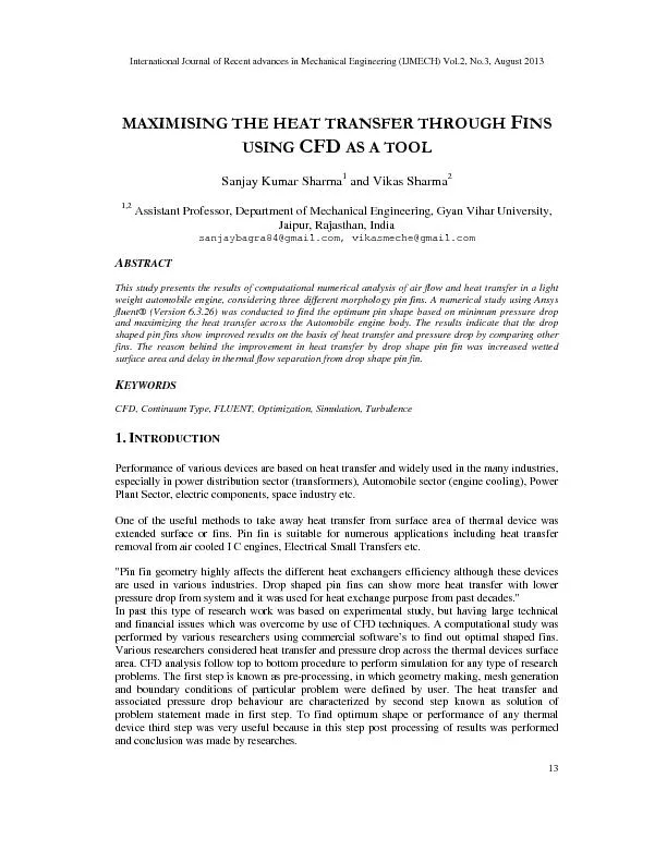
International Journal of R ecent advances in Mechanical Engineering IJMECH Vol2 No3 August 2013 The objective of t his study was to find out optimum type of fins used for heat removal applicatio ID: 280656

International Journal R ecent advances

Share:

Link:

Embed:

Download Presentation from below link

Download Pdf The PPT/PDF document "International Journal of Recent advances..." is the property of its rightful owner. Permission is granted to download and print the materials on this web site for personal, non-commercial use only, and to display it on your personal computer provided you do not modify the materials and that you retain all copyright notices contained in the materials. By downloading content from our website, you accept the terms of this agreement.


Presentation Transcript

International Journal of Recent advances in Mechanical Engineering (IJMECH) Vol.2, No.3, August 2013 13 \n \n   \r  \n \n\r Sanjay Kumar Sharma and Vikas Sharma2 1,2 Assistant Professor, Department of Mechanical Engineering, Gyan Vihar University, Jaipur, Rajasthan, India sanjaybagra84@gmail.com, vikasmeche@gmail.com BSTRACTThis study presents the results of computational numerical analysis of air flow and heat transfer in a light weight automobile engine, considering three different morphology pin fins. A numerical study using Ansys fluent® (Version 6.3.26) was conducted to find the optimum pin shape based on minimum pressure drop and maximizing the heat transfer across the Automobile engine body. The results indicate that the drop shaped pin fins show improved results on the basis of heat transfer and pressure drop by comparing other fins. The reason behind the improvement in heat transfer by drop shape pin fin was increased wetted surface area and delay in thermal flow separation from drop shape pin fin. EYWORDSCFD, Continuum Type, FLUENT, Optimization, Simulation, Turbulence 1.NTRODUCTIONPerformance of various devices are based on heat transfer and widely used in the many industries, especially in power distribution sector (transformers), Automobile sector (engine cooling), Power Plant Sector, electric components, space industry etc. One of the useful methods to take away heat transfer from surface area of thermal device was extended surface or fins. Pin fin is suitable for numerous applications including heat transfer removal from air cooled I C engines, Electrical Small Transfers etc. "Pin fin geometry highly affects the different heat exchangers efficiency although these devices are used in various industries. Drop shaped pin fins can show more heat transfer with lower pressure drop from system and it was used for heat exchange purpose from past decades." In past this type of research work was based on experimental study, but having large technical and financial issues which was overcome by use of CFD techniques. A computational study was performed by various researchers using commercial software’s to find out optimal shaped fins. Various researchers considered heat transfer and pressure drop across the thermal devices surface area. CFD analysis follow top to bottom procedure to perform simulation for any type of research problems. The first step is known as pre-processing, in which geometry making, mesh generation and boundary conditions of particular problem were defined by user. The heat transfer and associated pressure drop behaviour are characterized by second step known as solution of problem statement made in first step. To find optimum shape or performance of any thermal device third step was very useful because in this step post processing of results was performed and conclusion was made by researches. International Journal of R ecent advances in Mechanical Engineering (IJMECH) Vol.2, No.3, August 2013 The objective of t his study was to find out optimum type of fins used for heat removal application for automobile engine. This task was performed by using CFD as a tool. Three basic shapes of pin fins will be used in this study to find best shape. Maximising the heat transf pressure drop will be main criteria for selection of optimum pin fin. 2.EOMETRICAL ODELLING Methodology:- For CFD simulation, first of all geometry of the wind duct was created using GAMBIT (a software). After geometry creation next step is to mesh the geometrical model, which was also done using GAMBIT. Next step in GAMBIT is to declare continuum type and bou the surfaces generated. Finally a mesh file is created, which is imported in FLUENT. After importing mesh file in FLUENT, dimensional units for CFD domain are specified. In FLUENT desired turbulence model was selected for viscous modelling review. After selection of turbulence model boundary conditions are specified. Fluent has capability to store value of physical parameters for any point in the domain for analysis. Seven points were created to store the value phy pressure. FLUENT is now ready to simulate flow problem. Simulation was done for unsteady mode. Finally, post processing was done for result analysis. 3.ESCRIPTION OF UCT AND 3.1 Size of Duct Figure 1 Diagram of Test Ring in CFD 3.2 Geometric modelling Geometry: geometry generation is first step for making CFD domain. In gambit we can create both 2-D and 3- D shapes. In this case 3 In most of the pro blems shape of the domain is very complex. Some special operations are given in geometry mode to model complex geometries. The most significant operations are: unite, subtract, split, move, copy, align, rotate, translate etc. Figure 1 shows 3-D geometry used in our case. Furniture has been subtracted from main body of the room. ecent advances in Mechanical Engineering (IJMECH) Vol.2, No.3, August 2013 his study was to find out optimum type of fins used for heat removal application for automobile engine. This task was performed by using CFD as a tool. Three basic shapes of pin fins will be used in this study to find best shape. Maximising the heat transf er and minimising the pressure drop will be main criteria for selection of optimum pin fin. ODELLING AND ESH ENERATION For CFD simulation, first of all geometry of the wind duct was created using GAMBIT (a software). After geometry creation next step is to mesh the geometrical model, which was also done using GAMBIT. Next step in GAMBIT is to declare continuum type and bou ndary type for the surfaces generated. Finally a mesh file is created, which is imported in FLUENT. After importing mesh file in FLUENT, dimensional units for CFD domain are specified. In FLUENT desired turbulence model was selected for viscous modelling on the basis of literature review. After selection of turbulence model boundary conditions are specified. Fluent has capability to store value of physical parameters for any point in the domain for analysis. Seven points were created to store the value phy sical parameters such as temperature, velocity and FLUENT is now ready to simulate flow problem. Simulation was done for unsteady mode. Finally, post processing was done for result analysis. UCT AND EST OINTS Figure 1 Diagram of Test Ring in CFD Geometry: geometry generation is first step for making CFD domain. In gambit we can create D shapes. In this case 3 -D geometry of the duct was created. blems shape of the domain is very complex. Some special operations are given in geometry mode to model complex geometries. The most significant operations are: unite, subtract, split, move, copy, align, rotate, translate etc. geometry used in our case. Furniture has been subtracted from main body of ecent advances in Mechanical Engineering (IJMECH) Vol.2, No.3, August 2013 14 his study was to find out optimum type of fins used for heat removal application for automobile engine. This task was performed by using CFD as a tool. Three basic shapes of pin er and minimising the For CFD simulation, first of all geometry of the wind duct was created using GAMBIT (a software). After geometry creation next step is to mesh the geometrical model, which was also ndary type for the surfaces generated. Finally a mesh file is created, which is imported in FLUENT. After importing mesh file in FLUENT, dimensional units for CFD domain are specified. In on the basis of literature review. After selection of turbulence model boundary conditions are specified. Fluent has capability to store value of physical parameters for any point in the domain for analysis. Seven sical parameters such as temperature, velocity and FLUENT is now ready to simulate flow problem. Simulation was done for unsteady mode. Geometry: geometry generation is first step for making CFD domain. In gambit we can create blems shape of the domain is very complex. Some special operations are given The most significant operations are: unite, subtract, split, move, copy, align, rotate, translate etc. geometry used in our case. Furniture has been subtracted from main body of