/
Paralytic Twitch Sensor Paralytic Twitch Sensor

Paralytic Twitch Sensor - PowerPoint Presentation

conchita-marotz
conchita-marotz . @conchita-marotz
Follow
400 views
Uploaded On 2016-06-13

Paralytic Twitch Sensor - PPT Presentation

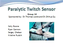
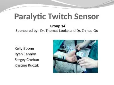
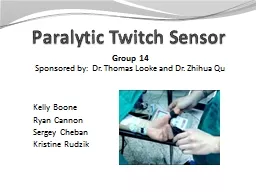
Group 14 Kelly Boone Ryan Cannon Sergey Cheban Kristine Rudzik Sponsored by Dr Thomas Looke and Dr Zhihua Qu Motivation Techniques for evaluating levels of muscle response today are not reliable ID: 360120

bit sensor display nerve sensor bit nerve display lcd power twitch bluetooth medical accurate microcontroller graphics voltage built testing

Share:

Link:

Embed:

Download Presentation from below link

Download Presentation The PPT/PDF document "Paralytic Twitch Sensor" is the property of its rightful owner. Permission is granted to download and print the materials on this web site for personal, non-commercial use only, and to display it on your personal computer provided you do not modify the materials and that you retain all copyright notices contained in the materials. By downloading content from our website, you accept the terms of this agreement.


Presentation Transcript

Slide1

Paralytic Twitch Sensor

Group 14Kelly Boone Ryan Cannon Sergey Cheban Kristine Rudzik

Sponsored by: Dr. Thomas

Looke

and Dr

.

Zhihua

QuSlide2

Motivation

Techniques for evaluating levels of muscle response today are not reliable.Anesthesiologist as the sensor: by touch or by sightOther methods require patients arms to be restrainedProblems: if restrained wrong it could lead to nerve damage in the patient or false readingsSeeing first hand when we shadowed Dr. Looke individually Trying to find a way to not let the blue shield that separates the sterile

field create an inconvenient way to measure the twitches.Slide3

Medical Background

AnesthesiaNobody is really sure how it works; all that is known about these anesthetics:Shuts off the brain from external stimuliBrain does not store memories, register pain impulses from other areas of the body, or control involuntary reflexesNerve impulses are not generatedThe results from the neuromuscular blocking agents (NMBAs) are unique to each individual patient. Therefore there is a need for constant monitoring while under anesthesia. Slide4

Medical Background

Different types of measuring:The thumb (ulnar nerve)Most popular site for measuringThe toes (posterior tibial nerve)If ulnar nerve isn’t available this is an accurate alternativeDifficult to reachThe eye (facial nerve)Not an accurate way to measureResults in an eyelid twitchSlide5

Medical Background

Pattern of electrical stimulation and evoked muscle response before and after injection of neuromuscular blocking agents (NMBA).

Train-of-Four (TOF) Twitch Slide6

Goals

Sensor that is relatively accurateAn interactive LCD touchscreenMinimal delay between the sensed twitch and the read outTrain of four (ToF), single twitch and tetanic stimulation patternsSafe to use in the operating roomAny part that touches the patient needs to either be easily cleaned or inexpensive enough to be disposed of after each useSlide7

Specifications

A maximum current of at least 30mAMaximum charge time of 0.5 seconds in order to have a reliable train of fourMinimum sampling frequency of 100HzConsistent sensor readout accuracy of ±25%Slide8

High Level Block DiagramSlide9

Nerve StimulatorSlide10

Voltage Multiplier

Built using a full wave Cockcroft–Walton generatorEvery pair of capacitors doubles the previous stages’ voltageVout = 2 x Vin(as RMS) x 1.414 x (# of stages)Slide11

Inductive-Boost Converter

Uses the inductor to force a charge onto the capacitor

555 timer provides reliable charging

Microcontroller triggered deliverySlide12

SensorsSlide13

Force-Sensitive Resistors (FSRs)

4 in. A201 Model

0.55 in. 1 in.

A301 ModelSlide14

Accelerometers

MMA8452QSlide15

LCD DisplaySlide16

LCD Display

4d-systems uLCD-43-PTItead Studio ITDB02-4.3 4.3

” displayEasy 5-pin interfaceBuilt in graphics controlsMicro SD-card

adaptor

4.0V to 5.5V

operation range

~

79

g

Has

already been used in medical instruments

~$140.00

4.3

” display

16

bit data interface

4

wire control interface

Built in graphics controller

Micro SD card slot

~$40.00

Not enough informationSlide17

4D-Systems uLCD-43-PT

Delivers multiple useful features in a compact and cost effective display.4.3” (diagonal) LCD-TFT resistive screenEven though it’s more expensive than the other screen we know that this screen works and it has already been used in medical devices. It can be programmed in 4DGL language which is similar to C.4D Programming cable and windows based PC is needed to programSlide18

PICASO-GFX2 Processor

Custom Graphics ControllerAll functions, including commands that are built into the chipPowerful graphics, text, image, animation, etc.Provides an extremely flexible method of customizationSlide19

MCUSlide20

Microcontroller

Important FeaturesLow costLarge developer supportEnough FLASH memoryLibraries AvailableWorks with our LCD displayPreferably through-hole packageSlide21

Microcontroller

Features

MSP430F5438A

PIC32MX150

ATmega328

Architecture

16-Bit RISC

32-Bit

RISC

8-Bit

AVR

Flash Memory

256 KB

128

KB

32 KB

Frequency

25 MHz

50 MHz

20 MHz

RAM

16 KB

32 KB

2 KB

I2C Bus

4

2

1

AD

Converter

x16, 12-bit

x10, 10-bit

x8,

10-bit

Power Usage

1.8

– 3.6V

2.3 – 3.6V

1.8 – 5.5V

I/O Pins

87

21

23

Package

SMD

28DIP

28DIP

Size

14.6 x 14.6

x 1.9 mm

34.6 x 7.2 x 3.4 mm

34.7 x 7.4 x 4.5 mmSlide22

BluetoothSlide23

Bluetooth

Important FeaturesBuilt-in antennaLow power consumptionEasy to setupAutomatic pairing preferablyRelatively low costSlide24

Wireless

Features

SPBT2632C2A.AT2

PAN1325A

Size

Small 11.6 x 13.5 x 2.9 mm

Very small 9.5

x 9 x 1.8 mm

Data Rate

1.5 Mbps

Max Data Rate

2.1

Mbps

Encryption Type

128-bit

Encryption

8-to-128

Bit Encryption

Integrated Antenna

Yes

Yes

Power

Consumption

2.1 – 3.6 V

1.7 – 4.8

V

Certifications

CE,

IC,

FCC, Bluetooth

FCC,

CE, NCC, Bluetooth

Program

Memory

256 KB

NoneSlide25

Power SupplySlide26

Power Supply

Initial power from Wall Plug, used for Voltage MultiplierConverted to 5V and 3.3V for use with ICsBackup: modified laptop chargerSlide27

Administrative ContentSlide28

Budget

Part

Price (projected)

PCB Board

$150

Batteries

$50

Microcontroller/Embedded Board

$125

Wiring

$20

Display

$140

Accelerometer

$15

Flexion Sensor

$15

Piezoelectric Sensor

$15

Force Meter

$45

Display Housing

$100

Electrodes

$38

Experimenter Board

$149

Bluetooth

Evaluation Kit

$99

USB Debugging Interface

$99

Total

$1,060Slide29

Budget

Part

Price Paid

Actual Price

LCD

Display (TFT LCD)

$159.44

$159.44

4

D-Programming

Cable

$26.04

$26.04

PIC32MX150

FREE

$4.10

Arduino

Uno-R3

33.64

33.64

Sensors

TekScan

Flexiforce

Sensor

FREE

$16.25

Flexiforce

Sensor

$16.74

$16.74

Pressure Sensors

$20.00

$64.70

Triple

Axis Accelerometer

$13.64

$13.64

TOTAL

$269.50

$334.55Slide30

Current ProgressSlide31

Next Steps

Start programming and testing the screen with the controllerTesting and narrowing sensor selectionBuild and modify the nerve stimulator designSlide32

Issues

Testing and demonstrating the final productGenerating the appropriate voltage (upwards of 1000VDC)Picking an accurate enough sensorSlide33

Issues

Testing and demonstrating the final productGenerating the appropriate voltage (upwards of 1000VDC)Picking an accurate enough sensorKelly’s stress levels!!! Slide34

Questions?