/
TA Fundamentals of hydrostatic level measurement  Page 1 of 11  
... TA Fundamentals of hydrostatic level measurement  Page 1 of 11  
...

TA Fundamentals of hydrostatic level measurement Page 1 of 11 ... - PDF document

conchita-marotz
conchita-marotz . @conchita-marotz
Follow
401 views
Uploaded On 2015-08-10

TA Fundamentals of hydrostatic level measurement Page 1 of 11 ... - PPT Presentation

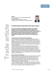
Enrico Bossart DiplIng BA graduate engineer Product Manager WIKA Alexander Wiegand SE Co KG Company Division Electronic Pressure Measurement TA Fundamentals of hydrostatic level measurem ID: 104196

Enrico Bossart Dipl.-Ing. (BA) (graduate

Share:

Link:

Embed:

Download Presentation from below link

Download Pdf The PPT/PDF document "TA Fundamentals of hydrostatic level mea..." is the property of its rightful owner. Permission is granted to download and print the materials on this web site for personal, non-commercial use only, and to display it on your personal computer provided you do not modify the materials and that you retain all copyright notices contained in the materials. By downloading content from our website, you accept the terms of this agreement.


Presentation Transcript

TA Fundamentals of hydrostatic level measurement Page 1 of 11 Enrico Bossart, Dipl.-Ing. (BA) (graduate engineer) Product Manager WIKA Alexander Wiegand SE & Co. KG Company Division - Electronic Pressure Measurement TA Fundamentals of hydrostatic level measurement Page 2 of 11 Thus, despite the apparent contradiction of an over-proportional increase or decrease in the volume or weight of a liquid with change in height, the hydrostatic pressure at the measuring point is solely proportional to the absolute filling height, and not to the filling quantity. A static liquid generates, through its specific density and the acting force of gravity, a corresponding weight force or hydrostatic pressure which increases proportionally with the filling height. Consequently, the hydrostatic pressure represents a direct measure of the fill level or degree of filling of a tank or vessel. Since, the hydrostatic pressure is not dependent upon the volume or the shape of a vessel, it can be used directly for the measurement of the fill level, but must be further processed to "measure" the fill quantity. From the measured level, using a 'tank linearisation table', the actual fill quantity present in the vessel can be calculated. A tank linearisation table documents, for different pressure values, the respective fill quantity present in the vessel. From the values documented, a curve can then be derived which presents the user a corresponding fill volume for every hydrostatic pressure measured. This calculation is usually carried out in the PLC, so that the operator has a display of the actual fill quantity present in the vessel, directly on-screen. In order to determine the fill quantity from the hydrostatic pressure with a high accuracy, the pressure sensor should be positioned, ideally, at the height of the required zero measurement. Based on this measuring point, the sensor will measure the hydrostatic pressure as a direct scale of the distance from the selected measuring point to the medium's surface. The measured hydrostatic pressure of a liquid, in addition to the weight force of the medium, also consists of the ambient pressure acting directly on the liquid's surface. The overlying pressure of the ambient air or gas pressure can be considered as a force which acts on the pressure sensor in addition to the liquid's weight force as a hydrostatic pressure. Level measurement in open, vented vessels In hydrostatic level measurement in open or vented basins or vessels, a continuous pressure compensation of the ambient air with the gas phase above the liquid takes place. Thus the ambient pressure that acts on the medium as an additional “force" always resembles the ambient pressure acting on the whole system, including the level sensor. If one therefore uses a pressure sensor with a relative pressure measuring cell, a pressure sensor that is compensated or vented (just like the tank) to the ambient pressure, it "automatically" compensates for the effect of this ambient pressure on the level measurement. This means that a relative pressure sensor in vented vessels and tanks completely "cancels out" the atmospheric pressure overlying on the liquid from the level measurement. Thus, the hydrostatic pressure corresponds only to the filling height of the liquid (Fig. 2). Therefore, the filling height of an open tank or vessel is calculated using the following equation: h = p / ( * g) p = hydrostatic pressure [bar (relative)] = density of the liquid [kg/m³] TA Fundamentals of hydrostatic level measurement Page 3 of 11 g = gravitational force or gravitational acceleration [m/s²] h = height of the liquid column [m] As a simple rule of thumb for water as a medium, one can assume that a pressure of 1 bar (relative) corresponds to a filling height of 10 m. Rule of thumb (media of density ~ 1000 kg/m³ ): h = 1 bar (relative) / (1000 kg/m³ * 10 m/s²) = 10 m The rule of thumb demonstrates that the hydrostatic pressure in a vessel is proportional to the filling height of the medium, as long as it maintains a constant density, completely independent fromshape or fill quantity. Level measurement in sealed, gas-tightvessels The level measurement in sealed, gas-tight vessels, which is frequently found in the chemical industry, requires a compensation of the pressure of the enclosed gas phase above the liquid. The enclosed pressure of the gas phase acts as an additional force on the liquid and distorts any hydrostatic pressure measurement at the base of the vessel. Thus, this distorting influence must be compensated through an additional pressure measurement of the gas phase. Frequently, a second pressure sensor is used for the measurement of the gas pressure. This application effectively represents a differential pressure measurement, where the two separate pressure measurements are offset against each other (Fig. 3). This offset calculation can be made either by two individual sensors or via an integrated differential pressure sensor. In this application, the sensors used can either be relative (sensor with ambient pressure compensation) or absolute pressure variants (sensor with sealed vacuum reference). Thus, the filling height of a sealed tank or vessel is calculated using the following equation: ) / ( * g) = hydrostatic pressure [bar] = pressure of the enclosed gas in the vessel [bar] = density of the fluid [kg/m³] g = gravitational force or gravitational acceleration [m/s²] h = height of the liquid column [m] Types of hydrostatic level sensors In hydrostatic level measurement, one can differentiate three types or designs of level sensors: conventional pressure transmitters, process pressure transmitters and submersible pressure transmitters, available in relative, absolute and differential pressure variants. For application in tanks and free-standing vessels, conventional pressure transmitters (Figs. 4 and 5) or process pressure transmitters (Fig. 6) are particularly suitable, either with a conventional pressure port (Fig. 4) or a flush diaphragm design (Fig. 5). Conventional pressure transmitters are the most commonly employed, due to their wide use throughout various industries, mostly without the need for special requirements on the measurement technology (such as scalability of the measuring range or integrated tank linearisation). TA Fundamentals of hydrostatic level measurement Page 4 of 11 Conventional sensors stand out through their excellent price/performance ratio. They are robust, simple to install and operate, fast, and available with a range of accuracies up to %. Process pressure transmitters, however, are primarily used in applications with special demands on the measurement technology (such as bus signals, scalability of the measurement range, integrated tank linearisation, etc.) and are mainly found in applications in the chemical and petrochemical industries. The extensive adjustability and high intelligence of these programmable process pressure transmitters is also reflected in their price level in relation to conventional industrial transmitters, easily five to ten times as expensive as a conventional pressure sensor. Specifically in the water and wastewater industry, submersible pressure transmitters ('level probes' or 'submersible probes’) are frequently used to measure the level in reservoirs, wells or other open bodies of water (Fig. 7). Submersible pressure transmitters are specifically designed to operate while continuously submerged in liquids. They mainly differ from conventional pressure sensors in their media resistance, pressure tightness, cable quality and ingress protection. The design of differential pressure transmitters (Fig. 8) is considered as state of the art technology within the chemical and petrochemical industry. Differential pressure transmitters offer the ability to measure and eliminate the effect of the gas phase of in a gas-tight sealed tank, and correctly display the level of the liquid phase within the tank.. The operator therefore has a hydrostatic level measurement which displays the correct liquid height without the need of any additional compensation or additional sensors. The sophistication of this measurement technique is however reflected in the costs of both the instrument itself as well as the corresponding installation. Advantages and limitations of hydrostatic level measurement Hydrostatic pressure and level measurement enjoys a consistently high popularity due to it’s high robustness, high reliability and simple installation of this technology. The following characteristics constitute the greatest advantages and limitations over other measuring principles: Advantages: Proven and established measuring principle with high reliability, field-tested millions of times Robust measuring process, uninfluenced by disruptive factors such as dust, foam, vapour, buildup, contaminants, etc. Reliable measurement unaffected by many physical characteristics such as conductivity, dielectric coefficient or viscosity Level measurement unaffected by vessel geometry and existing installed equipment Simple installation and operation of submersible pressure transmitters and conventional pressure sensors without the need for calibration or adjustment Direct contact with the medium Numerous alternative design variations and sensor technologies for almost every application TA Fundamentals of hydrostatic level measurement Page 5 of 11 Limitations: Unsuitable for bulk material Accurate measurement requires either media with constant density or continuous density measurement of the medium Hydrostatic level measurement in practice The selection of a level sensor is often affected by a great uncertainty with respect to how suitable a technology is for the specific application. The great popularity of hydrostatic sensors lies in their simple application, a low susceptibility to problems from installation through to their continuous operation, their high tolerance to disturbances and the suitability of the technology for almost all application conditions. Nevertheless, it is also important here to avoid a few pitfalls in order to use this measuring method effectively and safely for level measurement. The influence of temperature, especially its influence on the density of the specific medium, must always be incorporated into the calculation of the level for a correct level measurement. An increase in the process temperature may lead to a lower density of the medium and a correspondingly increasing level, however, not always in the same proportion as the increase in the hydrostatic pressure. This leads to an inaccuracy in the calculation, e.g. to a lower reading of the level. Therefore, hydrostatic level measurement is primarily used in applications which operate within known process limits or with a known medium density. Should the process have a strongly changing or an unknown density, this would normally be compensated for through additional sensors. Therefore, various pressure sensors with additional, integrated temperature sensors, are available which enable the measurement of the medium temperature for density compensation. The medium and its characteristics, in particular its viscosity and solids content, will decide between using a pressure sensor with a traditional design with pressure port or one with a flush diaphragm. A pressure sensor with a pressure port (Fig. 4) should always be used when the medium has a low viscosity and is free from coarse-grained contaminants. However, if a medium has a tendency to build-up, is highly viscous or contains a lot of particulates, then one should select a sensor with a flush diaphragm (Fig. 5). In contrast to a flush diaphragm sensor, a sensor with a pressure portcan become blocked or the media in it can harden or crystallise. Any blockage in the pressure port slows down the measurement, or, in the most extreme case, completely prevents a correct pressure measurement. If one pays attention to the characteristics of the medium to be measured when choosing a conventional pressure transmitter, then hydrostatic pressure measurement can be used reliably even under the harshest of conditions. Submersible pressure transmitters (Fig. 7), as a specific design variant of a pressure transmitter, are used in contaminated media, such as wastewater, as well as in clean media, such as fuel or groundwater. For this, both flush product variants as well as variants with large, widened pressure ports are used, in order to ensure a high reliability of level measurement in the submersed application. TA Fundamentals of hydrostatic level measurement Page 6 of 11 In the differential pressure measurement with process transmitters (Fig. 9) the mounting position is a common source of inaccuracies in the level measurement. The measuring points of the medium and the gas phase are typically connected to the differential measuring cell of the transmitter by oil-filled capillaries (in Fig. 9, indicated in blue and red respectively). The height difference of these measuring points to the differential pressure transmitter lead to an additional hydrostatic pressure within the capillaries (see Fig. 10) themselves. This effect generates an additional over- or under-pressure in the hydrostatic pressure measurement, ultimately distorting the measurement. The resulting inaccuracy of the measurement must be corrected within installation by a position correction and proper configuration of the differential pressure transmitter, so that a fully automatic compensation of this disturbance factor can be made. It is further on strongly recommended to position the transmitter below the height of the level measurement point in order to eliminate any negative hydrostatic pressure or under-pressure from the level measurement. What is the future of hydrostatics Through the wide spread utilization of industrial pressure sensors and due to the annual manufacturing of millions of hydrostatic sensors, hydrostatic pressure sensors have achieved a significant price advantage over many other level measurement methods. The utilization of pressure sensors for level measurement will continue to grow above all in general applications without any special requirements on the measurement technology. Consequently, in the future, hydrostatic level measurement will continue to show a growing market share against many other level measurement principles, and will enable cost-effective level measurement in many new applications. Trends Alternative materials In recent years one has been able to observe the trend for hydrostatic level measurement technology to replace alternative measurement principles, and to be used more and more in many process measurement applications. Thus, a clear trend has been recognisable towards the measurement of aggressive media (e.g. acids and bases) which go beyond the usual application conditions for the operation of conventional pressure sensors in machine building. These media, often present in process industries, are being met by pressure sensor manufacturers with a clear adjustment in their product design. Thus, more and more, one finds the use of alternative materials and coatings for conventional pressure sensors and their wetted parts. Titanium, gold, ceramic, Teflon and many other materials are already available on the market and are common material options for pressure sensors - and their importance will increase in the future. TA Fundamentals of hydrostatic level measurement Page 7 of 11 Hygienic design The keyword "hygienic design", originally derived from the pharmaceutical and food and beverage industries, is also finding ever-increasing appeal in the chemical industry. The specific needs of these industries – such as a maximum possible purity of the measured production batch, an optimised cleanability of all wetted parts of the process instrumentation or high media and ambient temperatures - have been implemented in a number of specialised hydrostatic pressure sensors. The benefits of hygienic design originate from the growing requirements in the manufacture of chemical and petrochemical products especially regarding purity and quality. Smaller batch sizes, faster and more frequent batch changes, consequently a higher flexibility in production - without the risk of cross-contamination through product residues from previous batches - is provided by the hygienic design of all wetted parts. As a result of these benefits, hydrostatic level sensors with hygienic design are now also finding a more frequent use in many conventional applications for process instrumentation in the chemical industry. More intelligent pressure sensors Hydrostatic pressure sensors have previously often been used in simple applications with a high sensitivity to price. Due to a continuing rise in complexity of control technology and process control, and also through the substitution of alternative measurement principles by hydrostatic level measurement, the demands on hydrostatic pressure sensors are increasing further. Requirements such as digital communication, programmability or internal tank linearisation have already been implemented in process pressure transmitters. These requirements are to be expected in the future in supposedly simpler and lower-priced industrial transmitters. Leading suppliers of industrial pressure sensors have already responded through new, special models. It is therefore to be expected that, in the future, users of hydrostatic level sensors will find a considerably increasing number of conventional industrial transmitters on the market with extensive configuration possibilities. Multiple measurands In the measurement of chemical parameters, such as chloride, oxygen and nitrogen content, measuring systems for the measurement of multiple measurands are a tested, accepted technology. In the measurement of physical parameters, on the other hand, previously one has focused on the measurement of a single measurand through a corresponding sensor,e.g. a temperature sensor for temperature measurement. In recent years, however, the demand for combined instrument solutions for physical measurands has been seen more and more. The combination of pressure and temperature measurement within a single pressure sensor can already be found frequently, primarily to minimise the number of instrumented measuring points. The trend towards combined sensor principles will, in the following years, lead to an increasing number of available pressure sensors on the market, and a growing market relevance for the combination of hydrostatic pressure respectively level and temperature measurement. TA Fundamentals of hydrostatic level measurement Page 8 of 11 Summary Hydrostatic level measurement technology has, in recent years, gained an exceptional market importance as a result of its simple and easily understood usage. Through its high durability and its tolerance to a large number of disturbances and unsteady process conditions, this technology will, for the foreseeable future, maintain its status as the most important sensor technology principle for level measurement. New applications and the substitution of alternative measurement principles will promote a further growth in the distribution of hydrostatic pressure sensors. In recent years, the manufacturers of industrial pressure sensors have, through alternative materials and an ever-growing complexity of pressure sensors, shaped hydrostatic level measurement technology to suit the requirements of future needs. Number of characters: 21.175 Source: 1. VDC Research Group, Inc.: What’s driving the process level measurement & inventory tank gauging markets, 2011 Figure 1: Illustration of the hydrostatic paradox Level measurement in open, vented tanks and vessels TA Fundamentals of hydrostatic level measurement Page 9 of 11 Level measurement in sealed, gas-tight tanks and vessels Product, WIKA S-10: Design – conventional pressure transmitter with pressure port Product, WIKA S-11: Design – conventional pressure transmitter with flush diaphragm Product, WIKA UT-10: Design - process pressure transmitter Product, WIKA LH-20: Design - submersible pressure transmitter TA Fundamentals of hydrostatic level measurement Page 10 of 11 Product, WIKA DPT-10: Design - differential pressure transmitter Hydrostatic level measurement using differential pressure sensors Figure 10: Effects of positioning on differential pressure sensors in level measurement Figure 11: possible title photo, ©iStockphoto.com TA Fundamentals of hydrostatic level measurement Page 11 of 11 WIKA Alexander Wiegand SE & Co. KG Alexander-Wiegand-Straße 30 63911 Klingenberg/Germany Tel. +49 9372 132-0 Fax +49 9372 132-406 info@wika.de www.wika.de