/
1 Combustion in CI Engine 1 Combustion in CI Engine

1 Combustion in CI Engine - PowerPoint Presentation

danika-pritchard
danika-pritchard . @danika-pritchard
Follow
424 views
Uploaded On 2015-12-08

1 Combustion in CI Engine - PPT Presentation

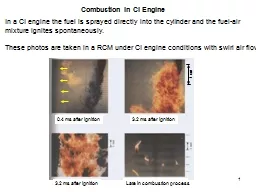
In a CI engine the fuel is sprayed directly into the cylinder and the fuelair mixture ignites spontaneously These photos are taken in a RCM under CI engine conditions with swirl air flow 04 ms after ignition ID: 218364

ignition fuel combustion engine fuel ignition engine combustion air injection delay high number knock temperature pressure gas time rate flame cetane octane

Share:

Link:

Embed:

Download Presentation from below link

Download Presentation The PPT/PDF document "1 Combustion in CI Engine" is the property of its rightful owner. Permission is granted to download and print the materials on this web site for personal, non-commercial use only, and to display it on your personal computer provided you do not modify the materials and that you retain all copyright notices contained in the materials. By downloading content from our website, you accept the terms of this agreement.


Presentation Transcript

Slide1

1

Combustion in CI Engine

In a CI engine the fuel is sprayed directly into the cylinder and the fuel-air

mixture ignites spontaneously.These photos are taken in a RCM under CI engine conditions with swirl air flow

0.4 ms after ignition

3.2 ms after ignition

3.2 ms after ignition

Late in combustion process

1 cmSlide2

2

In Cylinder Measurements

This graph shows the fuel injection flow rate, net heat release rate and

cylinder pressure for a direct injection CI engine.

Start of injection

Start of combustion

End of injectionSlide3

3

Combustion in CI Engine

The combustion process proceeds by the following stages:

Ignition delay (ab) - fuel is injected directly into the cylinder towards the end of the compression stroke. The liquid fuel atomizes into small drops and penetrates into the combustion chamber. The fuel vaporizes and mixes with the high-temperature high-pressure air.

Premixed combustion phase (bc) – combustion of the fuel which has mixedwith the air to within the flammability limits (air at high-temperature and high-pressure) during the ignition delay period occurs rapidly in a few crank angles.

Mixing controlled combustion phase (cd) – after premixed gas consumed, the burning rate is controlled by the rate at which mixture becomes available for

burning. The rate of burning is controlled in this phase primarily by the fuel-air mixing process. Late combustion phase (de) – heat release may proceed at a lower rate well

into the expansion stroke (no additional fuel injected during this phase). Combustion of any unburned liquid fuel and soot is responsible for this.Slide4

4

Four Stages of Combustion in CI Engines

Start of

injection

End of

injecction

-10

TC

-20

10

20

30Slide5

5

CI Engine Types

Two basic categories of CI engines:

Direct-injection – have a single open combustion chamber into which fuel is injected directlyIndirect-injection – chamber is divided into two regions and the fuel is

injected into the “prechamber” which is connected to the main chamber via anozzle, or one or more orifices.For very-large engines (stationary power generation) which operate at low

engine speeds the time available for mixing is long so a direct injection quiescent chamber type is used (open or shallow bowl in piston).As engine size decreases and engine speed increases, increasing amounts of swirl are used to achieve fuel-air mixing (deep bowl in piston)

For small high-speed engines used in automobiles chamber swirl is not sufficient, indirect injection is used where high swirl or turbulence is generated in the pre-chamber during compression and products/fuel blowdown and mix

with main chamber air.Slide6

6

Ignition Delay

Ignition delay is defined as the time (or crank angle interval) from when the

fuel injection starts to the onset of combustion.Both physical and chemical processes must take place before a significantfraction of the chemical energy of the injected liquid is released.Physical processes are fuel spray atomization, evaporation and mixing of fuelvapour with cylinder air.Good atomization requires high fuel-injection pressure, small injector hole

diam., optimum fuel viscosity, high cylinder pressure (large divergence angle).Rate of vaporization of the fuel droplets depends on droplet diameter, velocity,fuel volatility, pressure and temperature of the air.Chemical processes similar to that described for autoignition phenomenon

in premixed fuel-air, only more complex since heterogeneous reactions (reactions occurring on the liquid fuel drop surface) also occur.Slide7

7

Fuel Ignition Quality

The ignition characteristics of the fuel affect the ignition delay.

The ignition quality of a fuel is defined by its cetane number CN.For low cetane fuels the ignition delay is long and most of the fuel is injected before autoignition and rapidly burns, under extreme cases this produces anaudible knocking sound referred to as “diesel knock”.

For high cetane fuels the ignition delay is short and very little fuel is injected before autoignition, the heat release rate is controlled by the rate of fuel injection and fuel-air mixing – smoother engine operation.Slide8

8

Cetane Number

The method used to determine the ignition quality in terms of CN is analogous

to that used for determining the antiknock quality using the ON.The cetane number scale is defined by blends of two pure hydrocarbonreference fuels.By definition, isocetane (heptamethylnonane, HMN) has a cetane number of 15 and cetane (n-hexadecane, C16H34) has a value of 100.

In the original procedures a-methylnaphtalene (C11H10) with a cetane number of zero represented the bottom of the scale. This has since been replaced by

HMN which is a more stable compound.The higher the CN the better the ignition quality, i.e., shorter ignition delay.The cetane number is given by: CN = (% hexadecane)

+ 0.15 (% HMN)Slide9

9

Factors Affecting Ignition Delay

Injection timing

– At normal engine conditions the minimum delay occurs with the start of injection at about 10-15 BTC.The increase in the delay time with earlier or later injection timing occurs because of the air temperature and pressure during the delay period.Injection quantity – For a CI engine the air is not throttled so the load is variedby changing the amount of fuel injected.

Increasing the load (bmep) increases the residual gas and wall temperature which results in a higher charge temperature at injection which translates to a decrease in the ignition delay.Intake air temperature and pressure – an increase in ether will result in a decrease in the ignition delay, an increase in the compression ratio has the

same effect.Slide10

Flame Development

Mass fraction burned

Flame development angle

Dqd – crank angle interval during which flame kernal develops after spark ignition.Rapid burning angle

Dqb – crank angle required to burn most of mixtureOverall burning angle - sum of flame development and rapid burning anglesSlide11

11

Spark Timing

Spark timing relative to TC affects the pressure development and thus the

imep and power of the engine.Want to ignite the gas before TC so as to center the combustion around TC.The overall burning angle is typically between 40 to 60o, depending on engine speed.

Engine at WOT, constant

engine speed and A/F

motoredSlide12

Abnormal Combustion in SI Engine

Knock

is the term used to describe a pinging noise emitted from a SI engineundergoing abnormal combustion.The noise is generated by shock waves produced in the cylinder when unburned gas ahead of the flame auto-ignites.Slide13

Knock

As the flame propagates away from the spark plug the pressure and

temperature of the unburned gas increases.

Under certain conditions the end-gas can autoignite and burn very rapidly

producing a shock wave

The end-gas autoignites after a certain

induction time

which is dictated by

the chemical kinetics of the fuel-air mixture.

If the flame burns all the fresh gas before autoignition in the end-gas can

occur then knock is avoided.

Therefore knock is a potential problem when the burn time is long!

shock

P,T

time

time

P,T

end-gas

flameSlide14

i

) Compression ratio – at high compression ratios, even before spark ignition,

the fuel-air mixture is compressed to a high pressure and temperature which promotes autoignitionii)

Engine speed – At low engine speeds the flame velocity is slow and thus the burn time is long, this results in more time for autoignitionHowever at high engine speeds there is less heat loss so the unburned gas temperature is higher which promotes

autoignitionThese are competing effects, some engines show an increase in propensity toknock at high speeds while others don’t.

iii) Spark timing – maximum compression from the piston advance occurs at TC, increasing the spark advance makes the end of combustion crank angleapproach TC and thus get higher pressure and temperature in the unburned

gas just before burnout.Parameters Influencing KnockSlide15

Fuel Knock Scale

To provide a standard measure of a fuel’s ability to resist knock, a scale has

been devised in which fuels are assigned an octane number ON.The octane number determines whether or not a fuel will knock in a given

engine under given operating conditions. By definition, normal heptane (n-C7H16) has an octane value of zero andisooctane (C8H18) has a value of 100.

The higher the octane number, the higher the resistance to knock.Blends of these two hydrocarbons define the knock resistance of intermediate octane numbers: e.g., a blend of 10% n-heptane and 90% isooctane has an octane number of 90.A fuel’s octane number is determined by measuring what blend of these two

hydrocarbons matches the test fuel’s knock resistance.Slide16

Octane Number Measurement

Note the motor octane number is always higher because it uses more severe

operating conditions: higher inlet temperature and more spark advance.

The automobile manufacturer will specify the minimum fuel ON that will resist knock throughout the engine’s operating speed and load range.