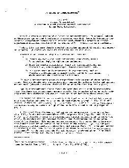
/
Atomics International North American Rockwell Corporation Canoga Park, Atomics International North American Rockwell Corporation Canoga Park,

Atomics International North American Rockwell Corporation Canoga Park, - PDF document

danika-pritchard
danika-pritchard . @danika-pritchard
Follow
402 views
Uploaded On 2016-08-09

Atomics International North American Rockwell Corporation Canoga Park, - PPT Presentation

superconductor the superconducting parameters locally different values the local transport current is impressed flux structure in the is larger the lower carry current conductor and is the are no ID: 440011

superconductor the superconducting parameters locally

Share:

Link:

Embed:

Download Presentation from below link

Download Pdf The PPT/PDF document "Atomics International North American Roc..." is the property of its rightful owner. Permission is granted to download and print the materials on this web site for personal, non-commercial use only, and to display it on your personal computer provided you do not modify the materials and that you retain all copyright notices contained in the materials. By downloading content from our website, you accept the terms of this agreement.


Presentation Transcript

Atomics International North American Rockwell Corporation Canoga Park, paper publish- comparable samples in similar superconductor the superconducting parameters locally different values. the local transport current is impressed, flux structure in the is larger the lower carry current conductor and is the are no we can superconductor behaves as applies also. makes all critical value, will change very rapidly the cylinder geometry which to destroy field 'variations or less.) directed circumferentially the surface. 19 Taylor 6 Bogner all of measurements of follow curve points labelled roughly above the surface surface current not immediately the ideal operative here Curve - a b C d e. f g .h i k 1 m n 0 .. P 4 r S TABLE VI Losses in Pure Niobium. Specific Reference Investigators Dimensions fluxoid structure. pinner we see of the flux lattice. sensitive also the interest and to complicate matters and a increasing losses the cooling REFERENCES Group 1 1. T. Pech, J.P. Duflot, and G. Fournet, Phys. Letters l6, 201 (1965). 2. T.A. Buchhold and P.J. Molenda, Cryogenics 2, 344 (1962). . 3. T.A. Buchhold and P.J.. Molenda, General Electric Progress Report No. 1; AF-33(657)-11722; BPSN 63-6899-737102 (1963), pp. 47-52. 4. - . Group 2 . 33. 34. 35. H.R. Hart and P.S. Swartz, General Electric Progress Report, loc. cit. Ref. 3, 36. 37. H. Voigt, Phys. Letters 20, 262 (1966). 38. H.A. Ullmaier, Phys. Letters 2l, 507 (1966). 39. R. Hancox, 271 (1967). Proc. 6th Accelerators, Cambridxe, Taylor, Phys; Soviet Physics JETP Letters Radiation Laboratory Rose-Innes, Cryogenics Appl. Phys. in Pure (Pergamon Press, completed Dec. Longituamol magnetic with pinning without pinning (bottom) (Ref. INTERNAL FIELD: IDEAL TYPE CURRENT POSSIBLE difference between ideal (no pinning) (I +i) PENETRATION DEPTH ac field Dynamic resistivity dynamic resistance changing field Fig. 7. Four ac loss regions. ,To helium gas (-0 ;Ev Cas fldwmeter II Nylon /I calorimeter Sample of superconducting WI,E (Bifilar winding on Tufnol former) Fig. 8. Experimental method: boil-off calorimeter (Ref. 8). - 531 - - - Fig. 10. Experimental method: calorimeter, using thermal conductivity of specimen (Ref. 5). - 532 - circuit: (Ref. Position lndicotor I I I I I I (corrected for the surface (H-AH l3 LOSS PER CYCLE = 24r2 j, FOR jc = 4 x IO5 A/cm2 LOSS = 1.05 x ( H - AH l3 [ JOULE/cm2] H in Oe Fig. 16. Modification of loss by the surface step AH. - 536 - open symbols both cases are for the portion of the curves cfsec; the than twice of Fig. n 3 Horizontal bars published values indicated range peak field. I I 111111 I I111111 I I Ill PEAK SURFACE FIELD (Oe) IO' IO2 lo3 lo4 Fig. 20. Reported ac losses in pure Nb (see Table VI). Same curve symbols as Fig. 14. . . - 540 - I I 1 i I Ill1 10-101 200 500 1000 Oe PEAK SURFACE FIELD Fig. 21. Reported ac losses in pure Pb. Curve a: Ref. 8. Curve b: Ref. 2. - 541 - mil niobium wire background field during Pb (Ref. loL 10 ,4 SURFACE FIELD PEAK (Oe) Fig. 24. Experimental ac critical currents plotted as frequency of the ac current vs the surface peak field created by the ac current. The curves numbered 1-5 are theoretical limits explained in the text. The points are referenced in Table VII.' - 543 -