/
GENERALISATION OF 3D BUILDING MODELS BY CELL DECOMPOSITION AND PRIMITI GENERALISATION OF 3D BUILDING MODELS BY CELL DECOMPOSITION AND PRIMITI

GENERALISATION OF 3D BUILDING MODELS BY CELL DECOMPOSITION AND PRIMITI - PDF document

danika-pritchard
danika-pritchard . @danika-pritchard
Follow
426 views
Uploaded On 2016-04-19

GENERALISATION OF 3D BUILDING MODELS BY CELL DECOMPOSITION AND PRIMITI - PPT Presentation

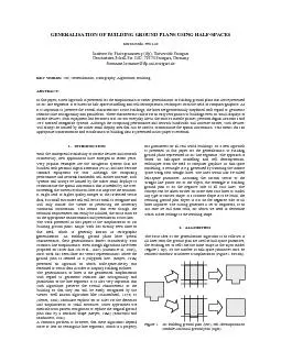
ground plans Several algorithms have been developed that remove line segments under a predefined length by extending and crossing their neighbour segments and by introducing constraints about their ID: 283732

ground plans. Several algorithms have

Share:

Link:

Embed:

Download Presentation from below link

Download Pdf The PPT/PDF document "GENERALISATION OF 3D BUILDING MODELS BY ..." is the property of its rightful owner. Permission is granted to download and print the materials on this web site for personal, non-commercial use only, and to display it on your personal computer provided you do not modify the materials and that you retain all copyright notices contained in the materials. By downloading content from our website, you accept the terms of this agreement.


Presentation Transcript

GENERALISATION OF 3D BUILDING MODELS BY CELL DECOMPOSITION AND PRIMITIVE INSTANCING Martin Kada Institute for Photogrammetry (ifp), Universität Stuttgart, Germany Geschwister-Scholl-Str. 24D, D-70174 Stuttgart martin.kada@ifp.uni-stuttgart.de Commission II, WG 3 KEY WORDS: Generalization, Algorithms, Building, Three-dimensional, GIS, Visualization ABSTRACT: The article presents a cartographic generalisation approach for 3D building models with regard to the thematic visualisation of urban landscapes. Based on our earlier work to utilise approximating planes for generating simplified cell decompositions of the inpu ground plans. Several algorithms have been developed that remove line segments under a pre-defined length by extending and crossing their neighbour segments and by introducing constraints about their angles and minimum distances (e.g. (Powitz 1973), (Regnauld et al. 1999), (Van Kreveld 2001), (Harrie 1999) and (Weibel 1996)). Other approaches use vector templates (Meyer 1989), (Rainsford and Mackaness 2002), morphological operators like opening and closing (Camara 2005), (Li 1996), least-squares adjustment (Sester 2000) or techniques from scale space theory (Mayer 1998). Nowadays, a few algorithms also exist that have been specifically designed for the generalisation of 3D building models. Forberg (2004) adapts the morphology and curvature space operators of the scale space approach to work on 3D building models. Thiemann and Sester (2004) do a segmentation of the building’s boundary surface with the purpose of generating a hierarchical generalisation tree. After a semantic interpretation of the tree’s elements, they can selectively be removed or reorganized to implement the elemental generalisation operators for simplification, emphasis, aggregation and typification. Another aggregation approach is proposed by Anders (2005). It works for linearly arranged building groups. Their 2D silhouettes, which are the results of three projections from orthogonal directions, are simplified, extruded and then intersected to form the generalised 3D model. With a strong focus on the emphasis of landmarks present Thiemann and Sester (2006) adaptive 3D templates. They categorise building models into a limited number of classes with characteristic shapes. A building model is then replaced by the most similar 3D template that is a best fit to the real object. Because the semantics of the template is known, the object itself or specific features of the model can be emphasised at will. The simplification of 3D models has been a major topic in the field of computer graphics. See e.g. the survey of Luebke et al. (2002) for an up-to-date summary of the most important work. However, these algorithms are designed for general models that approximate smooth surfaces and therefore typically do not perform well on 3D building models. The main reason is that building models consist of considerably fewer planar faces, but many sharp edges. Coors (2001), Rau et al. (2006) and Kada (2002) show that the simplification operators and metrics can be modified so that the characteristic properties of the building models can be preserved during their simplification. Despite the number of available 3D generalisation approaches, a continuous difficulty seems to be the simplification of the roof structure. Most algorithms avoid this problem by simply generating flat or pent roofs or assume that the roof type is already available as the result of a preceding interpretation. In this paper, we describe a generalisation approach for 3D building models and concentrate on a new procedural method to generate reasonable roof geometries. GENERALISATION OF 3D BUILDING MODELS We propose a two-stage generalisation algorithm for the geometric simplification of solitary 3D building models. As can be seen from the intermediate results of the example in Figure 1, the two stages consist in a total of five steps. The first stage generates a 2D decomposition of space that approximates the ground plan polygon by a disjoint set of quadrilateral primitives. We accomplish this by deriving plane equations from the major façade walls (1), subdividing the infinite space along these planes (2) and identifying the resulting cells that feature a high percentage of overlap with the original ground plan polygon (3). The second stage reconstructs the simplified geometry of the roof. Here, a cell decomposition and a new primitive instancing approach is shown where the roof parameters are determined individually for each cell so that they best fit the original model under distinct adjacency constraints (4). By altering those parameters, the simplification of the roof can be properly adjusted. A union operation of the resulting primitives composes the final 3D building model and concludes the generalisation (5). Figure 1. Original 3D building model (top left) and the five generalisation steps. GROUND PLAN CELL DECOMPOSITION The main idea of the generalisation approach using cell decomposition can be best described by using the analogy of sculpturing. The 3D object in question is reproduced from a large solid block. However, the sculptor is only allowed to make planar cuts through the whole block. Afterwards, she peels away the pieces that do not belong to the resulting sculpture and glues the remaining solids together to form the final shape. In order to create a simplified counterpart of a 3D building model, the number of executed cuts must be as few as possible, but still enough to produce the characteristic shape of the original object. We simulate this process by generating a cell decomposition from a set of planes that approximate the façade and roof polygons of the input model. A solid that generously fits the dimensions of the original model is subdivided along the direction of the planes. So the two main challenges of this approach are to automatically derive the planes from the boundary representation and to differentiate between building and non-building cells from the resulting decomposition. In the following two sections we will focus more thoroughly on these two subjects, which are followed by a presentation of some exemplary results. Cell Decomposition Cell decomposition is a form of solid modelling in which objects are represented as a collection of arbitrarily shaped 3D primitives that are topologically equivalent to a sphere (see Foley et al. 1990). The individual cells are usually created as instances from a pre-defined set of parameterised cell types that may even have curved boundary surfaces. Complex solids are then modelled in a bottom-up fashion by “gluing” the simple cells together. However, this operator restricts the cells to be nonintersecting, which means adjoining cells may touch each other but must not share any interior points. While cell decomposition is not as versatile as constructive solid geometry (CSG), it is sufficient for creating all possible building shapes. Moreover, the limitation to one operator greatly simplifies the whole modelling process and the implementation of the generalisation algorithm. The models in our cell decomposition approach also differ with regard to how they were constructed. Rather then being generated in a bottom-up fashion using parameterised primitives, the shape and the assembly of cells emerge from the subdivision. Generation of the Ground Plan Decomposition In our algorithm, the cell decomposition serves two purposes: First, it is build as an approximation of the building ground plan and is consequently per se also a generalization thereof. Second, it provides the basic building blocks for the reconstruction of the roof geometry. Since the input models are provided as 3D data, all computations are also performed in 3D, even though the dimension of the resulting cells is really 2D; or 2.5D if a height is applied like in the example of Figure 1. For clarity reasons, however, the accompanying Figure 2 to Figure 4 are given as 2D sketches. The faces in a polyhedral building representation are always planar. If the real building façade features round or curved elements, then they must be approximated in the model by small polygons. We therefore generate the cell decomposition by subdividing a finite 3D subspace by a set of vertical planes. Figure 2 e.g. shows a building and the cell decomposition which results from subdividing space along the façade segments. Figure 2. Building ground plan (left), overlaid decomposition of space along its façade segments (middle) and resulting cell decomposition (right). As it can be seen, the union of the cells is not yet a simplification of the original shape and the small cells complicate the reconstruction of the roof geometry. So instead of using each individual façade polygon, we cluster them together with a special buffer operation for the purpose of generating fewer planes that in turn produce a decomposition of fewer cells. However, these planes should correspond with the most important façade segments so that the decomposition reflects the characteristic shape of the object. The importance of a plane is measured as the surface area of all polygons that are included in the generating buffer and that are almost parallel to the created plane. Polygons with a different orientation are not counted. Generation of Decomposition Planes We implemented a greedy algorithm that generates the plane of highest importance from a set of input façade polygons. At this point, we ignore all roof polygons and only use polygons with a strict horizontal normal vector. By repeatedly calling the algorithm, new planes are added to the result set and all polygons inside the buffer are discarded from further processing. The generation of planes ends when no input polygons are left or when the importance of the created planes falls under a certain threshold value. At the beginning of the algorithm, buffers are created from the input polygons (see Figure 3). Each buffer is defined by two delimiting parallel planes that coincide with the position and normal direction of a generating polygon. These planes may move in opposite directions to increase the buffer area until a generalisation threshold is reached. The buffers are first sorted by their importance and then merged pair wise to create larger buffers. Starting with the buffer of highest importance, the buffers of lower importance are tested for their inclusion in this buffer. If all polygons of a buffer can be included into the one of higher importance without increasing the distance between their delimiting planes above the generalisation value, then the merge is valid and is executed. The algorithm stops when no more buffers can be merged and the averaged plane equation of the polygons of the buffer of highest importance is returned. Figure 3. Initial buffer from façade segments (left), delimiting planes of the maximised buffer (middle) and resulting averaged plane (right). In order to enforce parallelism and to support right angles of the façade segments, the resulting planes are analysed in a last step. If the angle of the normal vectors from two or more planes is found to be below a certain threshold, these planes are made parallel or rectangular. If the deviation is only a small angle, this can be done by changing the normal vector of the plane equation and adjusting the distance value. For larger values, a rotation of the planes around their weighed centroids of the polygons is chosen. For our computations, we use four threshold values. The most important one is the generalisation distance that the buffer planes may move apart. As this value also determines the distance of the planes used for the decomposition, it is also approximately the smallest ground plan feature length of the resulting set of cells. Another threshold value determines the lowest importance of a plane that is still a valid result. Here, the square of the generalisation distance is used. Buffers below that value probably do not contain polygons with a side length of the generalisation distance and are therefore not important. The last two threshold values are angles. As it is important for the roof construction that the cells are parallelograms, the angle for enforcing parallelism is rather large. We chose 30° for parallelism and 10° for right angles. See Figure 4 for the set of buffers that result in a simplified cell decomposition. Figure 4. Building ground plan (left), overlaid simplified decomposition of space along its façade segments (middle) and resulting cell decomposition (right). Generation of Cell Decomposition Once the planes have been determined, they are then used to generate the cell decomposition of the building model. Theoretically, an infinite 3D space should be subdivided brute force by the planes. However, as an infinite space is unpractical, a solid two times the size of the building’s bounding box is used. Because the plane equations were averaged from façade segments and therefore have no horizontal component, the space is only divided in two dimensions. The resulting cells are 2D polygons extruded into the third dimension. The decomposition consists of building and non-building cells. Only the building cells are of interest for further processing. The other cells should be discarded. However, these cells can not directly be identified from the decomposition process. A further step is necessary. For that reason, a percentage value is calculated that denotes the overlap of the cell with the original building ground plan. Cells that result in a high overlap value are considered building cells whereas the other cells are considered as non-building cells. A precise value can be computed by intersecting the cell with the ground plan polygon and dividing the resulting area by the area of the cell. As the cells are rather big, an overlap threshold of 50% is able to correctly distinguish between building and non-building cells. ROOF GENERALISATION VIA CELL DECOMPOSITION The roof structure for general 3D building models can be very complex. We therefore present two methods for their simplification. Both recreate a simplified version of the original roof structure for the previously generated ground plan cell decomposition. The first method extends the cell decomposition approach to the third dimension. It is general enough to recreate all roof shapes. As it will be shown in section 6, however, limiting the possible 3D shapes of the cells to a subset of common roof types can lead to a more suitable roof structure for a subset of common buildings. So far, the roof polygons have been neglected. Now they are used to determine the decomposition planes of arbitrary orientation in order to generate 3D cell decompositions from the ground plan cells. Although the decomposition is done per cell, the planes are determined globally from all roof polygons to ensure that neighbouring cells fit well against each other. We use the buffer approach as previously described. The subdivision process is then done with the subset of planes that has polygons in their buffer that intersected the respective cells. This avoids a heavy fragmentation of the cells. The resulting cells are now real 3D solids, so the classification in building and non-building cells has to be done in 3D space. Consequently, a percentage value that denotes the volume of the original building model inside each respective cell is computed. Figure 5 shows the decomposition of the example building of Figure 1 by the roof planes and the resulting building cells after their identification. Figure 5. Decomposition of the roof before (left) and after (right) identification of building cells. As can be seen in Figure 5, there are some inaccuracies in the resulting model. These are caused by planes that do not cut the 2.5D cells at exactly the same location in space. We remove these inaccuracies by a vertex contraction process that pulls the roof vertices to the closest ground cell corner point, edge or cell centre if they are within close distance. Figure 6 and Figure 7 show results of the generalisation algorithm for simple example models as well as rather complex landmarks. ROOF GENERALISATION VIA PRIMITIVE INSTANCING Generating simplified roof structures via 3D cell decomposition does not always produce good looking results. This is the consequence of the generality of the preceding approach, which neither interprets the original roof geometry nor restricts the resulting 3D cells to feature valid roof shapes. In this section, we first illustrate exemplarily the more frequent problems we encountered during our studies and then show how we avoid them by using an approach that is based on the solid modelling method called primitive instancing Figure 6. Simple example buildings in their original (grey) and generalised (blue) shapes. Figure 7. 3D landmarks in their original (left) and generalised (right) shape. Common Problems using Cell Decomposition If the roof structure is very flat, the buffer that creates the first approximating plane will include all roof polygons. And as this plane gets the slope of the first dominant polygon the algorithm encounters, a shed roof is generally generated (see Figure 8). A better generalisation would instead be a hipped or gabled roof that is similarly shaped as the original building roof. Figure 8. Original 3D building model (left) and its generalisation via cell decomposition (middle) and primitive instancing (right). Because the opposing slopes of approximating planes are not strictly aligned against each other, the generalisation to hipped and gabled roofs often results in asymmetric shapes (see Figure 9). However, symmetric roof structures are in most cases preferable. Figure 9. Original 3D building model (left) and its generalisation via cell decomposition (middle) and primitive instancing (right). For roofs with multiple sections or wings that have different eaves and ridges heights, the cells close to the valleys can have a low overlap with the original models. They are therefore not positively classified as building cells and are erroneously discarded. The missing cells disturb the appearance of the generalised building model as such a roof shape is likely to be wrong (see Figure 10). Figure 10. Original 3D building model (top) and its generalisation via cell decomposition (left) and primitive instancing (right). Primitive Matching In each of the above mentioned example situations, it is necessary to interpret the roof geometry in order to create a shape that resembles the original model and is symmetric and valid. In this article, we describe an interpretation that is both locally done for individual ground plan cells and also later on globally for the entire set of cells. As height discontinuities of roof elements are linked by façade polygons, they are already incorporated into the ground plan cell decomposition. It can therefore be assumed that cells don’t need to be divided any further in order to be assigned different roof primitives to better resemble the roof structure. The interpretation is first done per cell by instancing eight 3D primitives, each given one of the eight supported roof shapes and the ground plan quadrilateral of the base cell. At this point, we support the four most common roof types and their connecting elements as they are depicted in Figure 11. To ensure symmetric roof shapes, all the gabled and hipped primitives need a ground plan in the shape of a parallelogram. This prerequisite of the cells can be ensured during the generation of the ground plan decomposition by using only approximating planes parallel and rectangular to the general orientation of the building. If no such cell decomposition is possible, the resulting primitive must either be shaped with flat or shed roofs or be reconstructed with the previously described cell decomposition approach. Figure 11. The eight primitive types supported by the roof simplification. Each primitive type is parameterised in terms of roof properties like eaves height, ridge height, ridge length, etc. They are then matched with all possible combinations of parameter values against the original geometry of the cell area and the best match is kept. To find this best match, we have experimented with two comparison functions: the sum of squared height differences and the percentage of equal roof slopes measured between the roof surfaces of the primitive and the original model. For easier comparison, the original roof geometry is sub-sampled so that for each sample point the height and normal direction of the surface is known. The sample points can then be compared with the primitives’ faces. For the comparison of roof slopes, the normal directions of the two surfaces must be below a threshold which we defined to be below 10 degrees. Because the height difference is a squared distance and the comparison of roof slopes a percentage value, both functions are difficult to unite. So as yet, we mainly use the slopes to determine the primitive type. And only if the highest percentages are about the same value we use the distance value to make the final decision. Multiple Primitive Matching Occasionally, the decomposition of the ground plan produces too many small cells for which it is impossible to find roof types that fit well. We therefore join cells together to find combinations that better match the supported roof shapes. This is done by recursively joining two neighbour cells together in an exhaustive search. In addition, the comparison functions are now evaluated for all cells at once and the candidate cell set with the best total value is our new solution (e.g. Figure 12). Figure 12. Original 3D building model (left), cell decomposition (middle) and simplified version generalised with multiple primitive matching (right). The union of cells must form a proper roof structure when they are built together. However, some primitive shapes, in particular the connecting elements, are only valid for cells with the right number and arrangement of neighbour cells. E.g. the gabled corner primitive only results in a nice looking model if exactly two neighbour primitives connect at two consecutive sides with their gabled profile. The result will be a cross-gabled, cross-hipped or even a more complex gabled or hipped roof shape. To ensure that a cell receives a valid roof shape, we check and discard solutions that violate a set of rules that state whether the derived primitive is valid depending on the number and arrangement of neighbour cells. Roof Typification So far, we have only discussed the simplification of 3D building models. There are, however, other generalisation operators. One is typification, which is the replacement of a number of similar looking features by a lower number of features. This concept is applicable to recurring roof elements like e.g. parallel shed, gabled and hipped roofs that are quiet common for factories or shopping halls. Once the roof parameters of a cell have been determined, the number of recurring elements can be reduced for typification. See Figure 13 for an example where seven hipped roof elements of a building have been replaced by five elements. As the rim in the example is also parameterised, we can additionally retain or remove it by the same generalisation operator if required. Figure 13. 3D building model with uniform parallel hipped roof elements in its original shape (left) and before (middle) and after (right) typification. Simplification of Curved Elements Similar works the simplification of round and curved building elements. For the palace in Figure 14, the three tower elements were first identified from the ground plan polygon by their circular arranged façade segments. After their parameters were determined, all tower polygons were removed and the simplification of the remaining building model was performed by the primitive instancing approach as described. Afterwards, the towers were added again to the final model as simplified versions. Without an interpretation of the towers, these elements would be eliminated by the simplification or might even interfere with the generalization process and produce badly looking results. However, the addition of the towers is not possible with cell decomposition as the tower primitives overlap with the other primitives of the simplified building. The end result is a model in constructive solid geometry (CSG) where primitives are joined with the Boolean union operator. Figure 14. 3D building model with circular tower elements in its original shape (left), after generalisation of the main building (middle) and with simplified towers (right). CONCLUSION Map and map-like presentations are essential to communicate spatial information. As 3D city models are becoming standard products of surveying offices, map-like 3D presentations are only a matter of time until they become available for a wide audience. Because maps need to be mobile, such applications will run on mobile devices with all their limitations. As 2D generalisation operators are already a common tool to prepare data to the scale of maps, such a scale-depending transformation of 3D data will require new operators. This paper proposes a new algorithm for the simplification of solitary 3D building models. It is based on cell decomposition and primitive instancing. Geometric properties that are specific to buildings like the coplanarity, parallelism and rectangularity of façade segments are preserved during simplification or can even be enforced if needed. The generalisation is solely controlled by an intuitive distance threshold value that specifies the minimum size of the building elements that are created. The partition of the algorithm into two stages proved to be very effective as the cell decomposition of the building’s ground plan simplifies the generalisation of the roof structure. We have shown two approaches for roof simplification. We think that the interpretation of the roof shape is necessary in order to execute more elaborate simplification operations. ACKNOWLEDGEMENTS The research described in this paper is founded by “Deutsche Forschungsgemeinschaft” (DFG – German Research Foundation). It takes place within the Collaborative Research Centre No. 627 “NEXUS PATIAL ORLD ODELS FOR OBILE ONTEXTWARE PPLICATIONS” at the Universität Stuttgart. The 3D building models are provided by Stadtmessungsamt Stuttgart. REFERENCES Albert, J., Bachmann, M., Hellmeier, A., 2003. Zielgruppen und Anwendungen für Digitale Stadtmodelle und Digitale Geländemodelle – Erhebung im Rahmen der Arbeitsgruppe „Anwendungen und Zielgruppen“ der SIG3D im Rahmen der Initiative GDI-NRW.Anders, K.-H., 2005. Level of Detail Generation of 3D Building Groups by Aggregation and Typification. In: Proceedings of the XXII International Cartographic Conference, La Coruna, Spain. Buchholz, H., Döllner, J., Nienhaus, M., Kirsch, F., 2005. Real-Time Non-Photorealistic Rendering of 3D City Models. In: Proceedings of the 1st International Workshop on Next Generation 3D City Models, Bonn.Camara, U., Antonio, M., Lopez, A., Javier, F., 2005. Generalization Process for Urban City-Block Maps. In: Proceedings of the XXII International Cartographic Conference, La Coruna, Spain. Coors, V., 2001. Feature-Preserving Simplification in Web-Based 3D-GIS. In: Proceedings of the 1st InternatiSymposium on Smart Graphics. Hawthorne, USA, pp 22-28. Foley, J., van Dam, A., Feiner, S., Hughes, J., 1990. Computer Graphics: Principles and Practice (2, Addison-Wesley. Forberg, A., 2004. Generalization of 3D Building Data based on a Scale-Space Approach. In: The International Archives of the Photogrammetry, Remote Sensing and Spatial Information Sciences, Istanbul, Turkey, Vol. XXXV, Part B. Harrie, L.E., 1999. The Constraint Method for Solving Spatial Conflicts in Cartographic Generalisation. In: Cartography and Geographic Information SystemsKada, M., 2002. Automatic Generalisation of 3D Building Models. In: Proceedings of the Joint International Symposium on Geospatial Theory, Processing and Applications, Ottawa, Canada. Kada, M., 2006. 3D Building Generalization based on Half-Space Modeling. In: Proceedings of the ISPRS WorksMultiple Representation and Interoperability of Spatial DataHannover, Germany. Kada, M. and Luo, F., 2006. Generalisation of Building Ground Plans using Half-Spaces. In: The International Archives of the Photogrammetry, Remote Sensing and Spatial Information Sciences, Vol. 36, Part 4, "Geospatial Databases for Sustainable Development", Goa, India. Li, Z., 1996. Transformation of Spatial Representations in Scale Dimension. In: International Archives of Photogrammetry and Remote Sensing. Vol. 31, Part B3/III, pp. 453-458. Luebke, D., Reddy, M., Cohen, J.D., 2002. Level of Detail for 3D Graphics, Morgan Kaufmann, USA. Mayer, H., 1998. Scale-Space Events for the Generalization of 3D-Building Data. In: International Archives of Photogrammetry and Remote Sensing, Vol. 32, Part 3/1, pp. 520-536. Meyer, U., 1989. Generalisierung der Siedlungsdarstellung in digitalen Situationsmodellen. Wissenschaftliche Arbeiten der Fachrichtung Vermessungswesen der Universität Hannover (159), Ph.D. Thesis. Powitz, B.-M., 1973. Zur Automation der Kartographischen Generalisierung topographischer Daten in Geo-Informationssystemen, Wissenschaftliche Arbeiten der Fachrichtung Vermessungswesen der Universität Hannover (185), Ph.D. Thesis. Rainsford, D., Mackaness, W.A., 2002. Template Matching in Support of Generalisation of Rural Buildings: In: D. Richardson und P.v. Oosterom (eds.): Advances in Spatial Data Handling, 10th International Symposium on Spatial Data Handling. Springer-Verlag, Berlin, pp. 137-152. Rau, J.Y., Chen, L.C., Tsai, F., Hsiao, K.H., Hsu, W.C., 2006. Automatic Generation of Pseudo Continuous LoDs for 3D Polyhedral Building Model. In: Innovations in 3D Geo Information Systems, Springer Verlag, Berlin. Regnauld, N., Edwardes, A., Barrault, M., 1999. Strategies in Building Generalization: Modelling the Sequence, Constraining the Choice. In: Progress in Automated Map Generalization – ACI. Sester, M., 2000. Generalization based on Least Squares Adjustement. In: International Archives of Photogrammetry and Remote Sensing, Vol. 33, Part B4/3, Amsterdam, pp. 931-Staufenbiel, W., 1973. Zur Automation der Generalisierung topographischer Karten mit besonderer Berücksichtigung großmaßstäbiger Gebäudedarstellungen, Wissenschaftliche Arbeiten der Fachrichtung Vermessungswesen der Universität Hannover (51), Ph.D. Thesis. Thiemann. F, Sester, M., 2004. Segmentation of Buildings for 3D-Generalisation. In: Working Paper of the ICA Workshop on Generalisation and Multiple Representation, Leicester, UK. Thiemann. F, Sester, M., 2006. 3D-Symbolization using Adaptive Templates. In: Proceedings of the GICON, Wien, Austria. Walter, V., 2005. Phoogle the Web – Google’s Approach of Spatial Data Visualisation. In: Dieter Fritsch (Ed.), Photogrammetric Week ’05, Wichmann Verlag, Heidelberg, pp. 321-330. Weibel, R., 1996. A Typology of Constraints to Line Simplification. In: Proceedings of the 7th InternatiConference on Spatial Data Handling, pp. 533-546. Van Kreveld, M., 2001: Smooth Generalization for Continuous Zooming. In: Proceedings of the ICA, 4th WorksProgress in Automated Map Generalization, Peking, China.